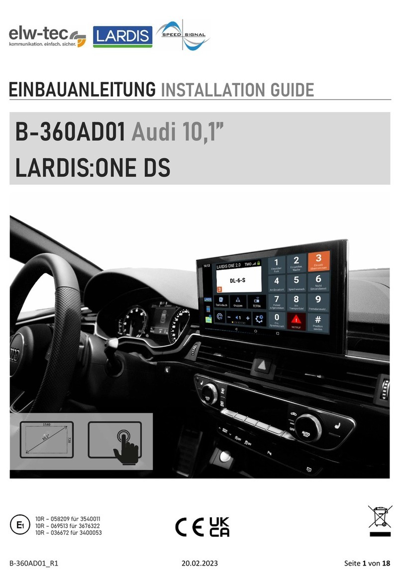
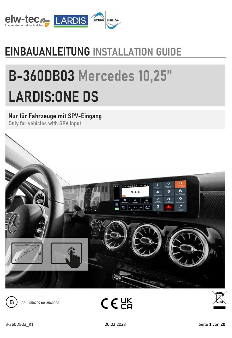
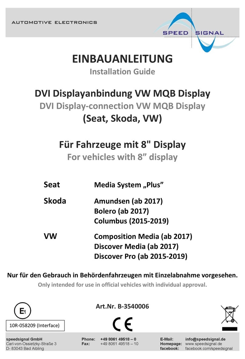
Speedsignal B-360DB06 User manual

B-360DB06_R1 20.02.2023 Seite 1 von 25
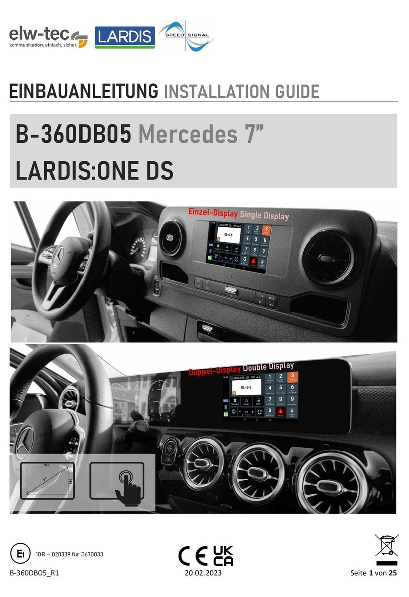
EINBAUANLEITUNG
INSTALLATION GUIDE
B-360DB06 Mercedes 10,25”
LARDIS:ONE DS
1920
720
Für Fahrzeuge mit oder ohne SPV-Eingang
For vehicles with or without SPV input
Einzel-Display Single Display
10R – 020339 für 3670033

B-360DB06_R1 20.02.2023 Seite 2 von 25
Fahrzeuge Vehicles
Mercedes
Infotainmentsystem
MBUX NTG 6
Ausstattungscode bei Sprinter:
Equipment code for Sprinter:
CODE E4M
Der DisplaySwitch funktioniert nur für
Fahrzeuge, die das genannte
Infotainmentsystem haben.
The DisplaySwitch works only for vehicles
that have the mentioned infotainment
system.
Display
Auflösung Resolution
1920*720
Diagonale Diagonal
10,25“ = 26 cm
A W177 (2018-)
B W247 (12/2018-)
CLA Baureihe 118 (2019-)
GLA H247 (2020-)
GLB X247 (2019-)
GLE V167 (2018-)
Sprinter III W907, W910 (2018-)

B-360DB06_R1 20.02.2023 Seite 3 von 25
Lieferumfang Scope of delivery
DisplaySwitch Set Mercedes 10,25“
DisplaySwitch Set Mercedes 10,25“
Powermanagement Set Mercedes
Powermanagement Set Mercedes
Mono-Verstärker Set
Mono Amplifier Set
Bordrechner Set Mercedes 10,25”
On-board computer set Mercedes 10,25”
3676315
356ASRGN1911
369DB01-02
Ohne Artikelnummer
Without article number
C-3670079
3630108
C-3674727-USB27
356ASRGN1909
3670033
C-3670033
3910030-02
3911137
Ohne Artikelnummer
Without article number
3630104
3630105
3630107
C-3676317
3630098
C-3674727-USB60

B-360DB06_R1 20.02.2023 Seite 4 von 25
Einbau Part 1: DisplaySwitch Installation part 1: DisplaySwitch
1. Ausbau Headunit (Fundort fahrzeugabhängig)
2. Plug&Play Anschluss der Kabelsätze
3. Anschluss der Interfaces an Kabelsatz
4. Installation des Tasters
5. 5m USB-Verlängerungskabel und 5m DVI auf HDMI Kabel in den Kofferraum verlegen
1. removal of headunit (location depends on vehicle)
2. plug&play connection of the cable sets
3. connection of the interfaces to the cable set
4. installation of the button
5. Install 5m USB extension cable and 5m DVI to HDMI cable in the trunk

B-360DB06_R1 20.02.2023 Seite 5 von 25
Im Lieferumfang ist ein Fakra-Kabelset enthalten, welches vor Beginn des Einbaus entsprechend zusammengesteckt werden muss.
Im Folgenden wird dies gezeigt.
The scope of delivery includes a Fakra cable set, which must be plugged together accordingly before starting the installation. This is shown below.
Fakra-Kabel 3630098 Fakra cable 3630098
D
B
C
A
E
C
A
Die übrig gebliebenen Kabel bzw. Stecker sind für den weiteren Einbau irrelevant.
The remaining cables or connectors are irrelevant for further installation.
B
A
B
Variante 1
Benötigt bei Einbau S.8, S.9, S.11
Variant 1
Required for installation p.8, p.9, p.11
Variante 2
Benötigt bei Einbau S.7
Variant 2
Required for installation p.7

B-360DB06_R1 20.02.2023 Seite 6 von 25
Fahrzeug mit Einzel-Display: Einbau hinter dem Display Seite 7
Fahrzeug mit Einzel-Display: Einbau hinter der Headunit Seite 8
Fahrzeug mit Doppel-Display: Einbau hinter dem Display Seite 9-10
Fahrzeug mit Doppel-Display: Einbau hinter der Headunit Seite 11-12
Allgemeines für alle Einbau-Varianten Seite 13-14
Vehicle with single display: Installation behind the display Page 7
Vehicle with single display: Installation behind the headunit Page 8
Vehicle with double display: Installation behind the display Page 9-10
Vehicle with double display: Installation behind the headunit Page 11-12
General information for all installation variants Page 13-14
Übersicht Einbau Installation overview

B-360DB06_R1 20.02.2023 Seite 7 von 25
Blau markierten Stecker (1) an den Steckplatz des zuvor
ausgesteckten Stecker der Headunit anschließen. Orange
markierten Stecker (2) an zuvor abgesteckten Stecker an-
stecken.
Connect the plug marked in blue (1) to the slot of the previously
unplugged plug of the head unit. Connect the plug marked in or-
ange (2) to the previously unplugged plug.
Einbau hinter Display für Einzel-Display Installation behind display for single display
Display ausbauen und markierten, grünen Stecker abste-
cken.
Remove display and disconnect marked green connector.
1
2
Lila markierten Stecker „A“ am Interface 3676315 am Ein-
gang „Display“ anstecken.
Grün markierten Stecker „B“ am Eingang „Headunit“ anste-
cken.
Connect the connector "A" marked in purple to the "Display" input
on interface 3676315.
Connect the plug marked green "B" to the "Headunit" input.
3
1
B
2
A
A
B

B-360DB06_R1 20.02.2023 Seite 8 von 25
Blau markierten Stecker (1) an den Steckplatz des zuvor
ausgesteckten Stecker der Headunit anschließen. Orange
markierten Stecker (2) an zuvor abgesteckten Stecker an-
stecken.
Connect the plug marked in blue (1) to the slot of the previously
unplugged plug of the head unit. Connect the plug marked in or-
ange (2) to the previously unplugged plug.
Einbau hinter Headunit für Einzel-Display Installation behind headunit for single display
Headunit ausbauen. Hinter der Headunit befindet sich ein
grüner Doppel-Fakra-Stecker. Diesen abstecken.
Remove the head unit. Behind the headunit there is a green dou-
ble fakra connector. Disconnect it.
1
2
Lila markierten Stecker „A“ am Interface 3676315 am Ein-
gang „Headunit“ anstecken.
Grün markierten Stecker „B“ am Eingang „Display“ anste-
cken.
Connect the connector "A" marked in purple to the "Headunit" in-
put on interface 3676315.
Connect the plug marked green "B" to the "Display" input.
3
1
B
2
A
A
B

B-360DB06_R1 20.02.2023 Seite 9 von 25
Nun muss der Kabelsatz angesteckt werden. Blau markier-
ter Stecker (1) am Steckplatz des grünen Eingangs anste-
cken. Grün markierter Stecker (3) am fahrzeugseitigen, zu-
vor abgesteckten grünen Stecker anstecken.
Now the cable set must be plugged in. Plug the blue-marked con-
nector (1) into the green input slot. Plug the plug (3) marked
green into the green plug on the vehicle side that was previously
unplugged.
Einbau hinter Display für Doppel-Display Installation behind display for double display
Display ausbauen und nach vorne klappen. Dafür muss zu-
erst die, mit dem Pfeil markierte, Plastikabdeckung ober-
halb des Displays entfernt und anschließend zwei Schrau-
ben entfernt werden.
Remove the display and fold it forwards. First remove the plastic
cover above the display marked with the arrow and then remove
two screws.
1
3
Nun den orange markierten Stecker (4) am Display-Inter-
face 3676315 am Eingang „Display“ anstecken. Anschlie-
ßend den violett markierten Stecker (5) am Display-Inter-
face 3676315 am Eingang „Headunit“ anstecken.
Now connect the plug marked orange (4) to the "Display" input on
the display interface 3676315. Then connect the connector (5)
marked in violet to the "Headunit" input on the display interface
3676315.
4
1
3
4
5
4
5
Markierten, grünen Stecker abstecken.
Disconnect the marked green plug.
2

B-360DB06_R1 20.02.2023 Seite 10 von 25
Schwarzen Stecker vom markierten Steckplatz der
Headunit abstecken, Gehäuse herausziehen. Hier wird
Masse und +12V abgegriffen.
Disconnect the black plug from the marked slot of the headunit,
pull out the housing. Ground and +12V are tapped here.
5
+12V: Pin 14, rot-grau red-grey
Masse Ground: Pin 1, braun brown
6

B-360DB06_R1 20.02.2023 Seite 11 von 25
Nun muss der Kabelsatz angesteckt werden. Blau markier-
ter Stecker (1) am Steckplatz des pinken Eingangs anste-
cken. Grün markierter Stecker (3) am fahrzeugseitigen, zu-
vor abgesteckten pinken Stecker anstecken.
Now the cable set must be plugged in. Plug the blue-marked con-
nector (1) into the pink input slot. Plug the plug (3) marked green
into the pink plug on the vehicle side that was previously un-
plugged.
Einbau hinter Headunit für Doppel-Display Installation behind headunit for double display
Die Headunit befindet sich an markierter Stelle im Fahrer-
fußraum.
The headunit is located at the marked position in the driver's
footwell.
1
3
Nun den orange markierten Stecker (4) am Display-Inter-
face 3676315 am Eingang „Headunit“ anstecken. Anschlie-
ßend den violett markierten Stecker (5) am Display-Inter-
face 3676315 am Eingang „Display“ anstecken.
Now connect the plug marked orange (4) to the "Headunit" input
on the display interface 3676315. Then connect the connector (5)
marked in violet to the "Display" input on the display interface
3676315.
4
3
4
5
4
5
Nun muss sowohl der pinke Stecker (1), als auch der mar-
kierte, schwarze Stecker (2) abgesteckt werden.
Now both the pink plug (1) and the marked black plug (2) must be
disconnected.
2
2
1
1

B-360DB06_R1 20.02.2023 Seite 12 von 25
Hier zu sehen: schwarzer Stecker von Headunit abgesteckt
(siehe Schritt 2). An diesem Stecker können Masse und +12V
abgegriffen werden. Dafür muss die Geäusekappe entfernt
werden.
Here you can see: black plug disconnected from headunit (see
step 2). Ground and +12V can be tapped at this connector. The
housing cap must be removed for this.
5
+12V: Pin 14, rot-grau red-grey
Masse Ground: Pin 1, braun brown
6

B-360DB06_R1 20.02.2023 Seite 13 von 25
Am Interface 3676315 das 5m HDMI auf DVI Kabel anschlie-
ßen und in den Kofferraum verlegen.
Connect the 5m HDMI to DVI cable to interface 3676315 and install
it in the trunk.
2
Am Kabelsatz das 5m USB-Verlängerungskabel
anschließen und in den Kofferraum verlegen.
Die Verbindung sollte mit Klebeband fixiert werden.
Connect the 5m USB extension cable to the cable set and install it
in the trunk.
The connection should be fixed with tape.
83
Allgemeines zum Einbau General information on installation
Abgebildete Leitungen des Kabelsatzes C-3676317 tech-
nisch einwandfrei mit dem Fahrzeug verbinden.
Braun: Masse
Rot: +12V
8-poligen Microfit-Stecker vom Kabel C-3676317 an das In-
terface 3676315 anschließen.
Connect the illustrated wires of cable set C-3676317 to the vehi-
cle in a technically correct manner.
Brown: Ground
Red: +12V
Connect 8-pin microfit connector from cable C-3676317 to inter-
face 3676315.
1
*
Die abgebildete, lilane Leitung ist ein Masse geschalteter Eingang, welcher bei einem anliegenden Masse-Signal zurück auf die originale
Ansicht switcht. Beispielsweise kann man so die PDC- bzw. Rückfahrkamera-Ansicht einblenden lassen.
The violet wire shown is a ground switched input, which switches back to the original view when a ground signal is present. For example, you can display
the PDC or rear view camera.
*

B-360DB06_R1 20.02.2023 Seite 14 von 25
Beide 5m Kabel
hinter den
Verkleidungen in den Koffer-
raum verlegen.
Install both 5 m cables behind
the trims in the trunk.

B-360DB06_R1 20.02.2023 Seite 15 von 25
Einbau Part 2: PMA Installation part 2: PMA
1. Anschluss Stromversorgung (+ Sicherungen)
2. Anschluss CAN-Bus (fahrzeugabhängig)
3. Taster (Funk-Hauptschalter) in der Front verbauen
1. power supply connection (+ fuses)
2. connection CAN bus (depending on vehicle)
3. install the push-button (radio main switch) in the front

B-360DB06_R1 20.02.2023 Seite 16 von 25
Einbau PMA Installation PMA
Der Powermanagementadapter wird, wie alle folgenden
Komponenten; im Kofferraum verbaut.
Üblicherweise wird hierfür die Reserverad-Mulde genutzt.
The powermanagementadapter, like all the following components,
is installed in the trunk.
The spare wheel compartment is usually used for this purpose.
1
Hauptkabelsatz C-3670079 an Powermanagementadapter
369DB01-02 anschließen.
Connect main cable harness C-3670079 to
powermanagementadapter 369DB01-02.
2
C
-
3
670079
1. Anschluss an PMA
2. Stromversorgung an Mono Verstärker
3. Anschluss Taster (hinter Verkleidung ins Cockpit verlegen)
4. Anschluss CAN-Bus (fahrzeugspezifisch)
5. Stromversorgung Funkgerät
6. Anschluss Stromversorgung an Fahrzeugbatterie
7. Stromversorgung Bordcomputer
1. connection to PMA
2. power supply to mono amplifier
3. connection to push-button (install behind trim in cockpit)
4. CAN-bus connection (vehicle-specific)
5. radio power supply
6. power supply connection to vehicle battery
7. power supply to on-board computer
7
6
5
4
3
2
1

B-360DB06_R1 20.02.2023 Seite 17 von 25
Der Anschluss des CAN-Bus ermöglicht es dem Bordrechner beim Anlassen der Zündung oder wahlweise beim Aufsperren des Fahr-
zeugs hochzufahren. Des Weiteren wird hierdurch auch die Tag- / Nacht-Umschaltung ermöglicht
The connection of the CAN bus enables the on-board computer to start up when the ignition is started or optionally when the vehicle is unlocked.
Furthermore, this also enables the day/night switchover.
3. Anschluss CAN-Bus CAN bus connection
Die abgebildeten CAN-Leitungen müssen mit dem CAN-Bus des Fahrzeugs (verdrilltes Adern-Paar)
verbunden werden. Wichtig ist, dass die abgebildeten CAN-Leitungen relativ nah am PMA ange-
schlossen werden. Überschüssiges Kabel kürzen!
- CAN High: weiß-gelb
- CAN Low: weiß-braun
Es empfiehlt sich den CAN-Bus im Kofferraum abzugreifen, wichtig ist, dass der gewählte CAN-
Bus folgende Signale bereit stellt:
- Zündung (Klemme 15)
- Hell-Dunkel-Erkennung (Tag- / Nacht-Umschaltung)
The CAN wires shown must be connected to the vehicle's CAN bus (twisted pair of wires). It is important that
the CAN wires shown are connected relatively close to the PMA. Shorten excess cable!
- CAN High: white-yellow
- CAN Low: white-brown
It is recommended to tap the CAN bus in the trunk. It is important that the selected CAN bus provides the
following signals:
- Ignition (terminal 15)
- Light/dark detection (day/night changeover)
Gängige CAN-Bus Farben: Common CAN bus colours:
MQB Plattform: VW / SEAT / Skoda + T6.1
- CAN High: grün (oder orange-grün) green (or orange-green)
- CAN Low: orange-braun orange-brown
MQB evo Plattform: VW / SEAT / Skoda + T6.1
- CAN High: grün green
- CAN Low: orange-braun orange-brown
MLB evo Plattform:
- CAN High: lila violet
- CAN Low: orange-braun orange-brown
MEB Plattform:
- CAN High: grün green
- CAN Low: orange-braun orange-brown
Audi:
- CAN High: grün green
- CAN Low: orange-braun orange-brown
Volvo:
- CAN High: weiß-grün white-green
- CAN Low: grün-gelb green-yellow
Ford:
- CAN High: grün (oder blau-grün) green (or blue-green)
- CAN Low: weiß (oder weiß-grün) white (or white-green)
Mercedes
- CAN High: braun-rot brown-red
- CAN Low: braun brown

B-360DB06_R1 20.02.2023 Seite 18 von 25
6. Anschluss Stromversorgung Power supply connection
1. Anschluss an Fahrzeug-Batterie
2. Kleiner Sicherungskasten
3. Quetschverbinder für rote Leitungen
4. Sicherungen für Hauptstromversorgung
1. connection to vehicle battery
2. small fuse box
3. crimp connector for red wires
4. fuses for main power supply
1
2
3
4
rote Leitung mit größerem Querschnitt: 10A Sicherung
rote Leitung mit kleinerem Querschnitt: 3A Sicherung
Red wire with larger cross-section: 10A fuse
Red wire with smaller cross-section: 3A fuse

B-360DB06_R1 20.02.2023 Seite 19 von 25
PMA Features PMA features
Spannungsüberwachung:
- Konstante Ausgabe von 12V
- LED des Funkhauptschalters blinkt bei drohender Unterspannung (Spannung < 11,8V)
- LED des Funkhauptschalters leuchtet bei Unterspannung (Spannung < 10,8V)
Voltage monitoring:
- Constant output of 12V
- LED of the radio main switch flashes in case of impending undervoltage (voltage < 11.8V)
- LED of the radio main switch lights up in case of undervoltage (voltage < 10.8V)
Geregeltes Hoch- und Runterfahren:
- Der Powermanagementadapter ermöglicht ein geregeltes Hoch- und Runterfahren des angeschlossenen PC`s und Funkgeräts
- Ausgelöst wird dies entweder durch Betätigung des Funkhauptschalters, oder durch den CAN-Bus (Zündplus)
- Wie das geregelte Hoch- und Runterfahren erfolgt, ist durch die Dip-Schalter frei einstellbar
Controlled start-up and shutdown:
- The power management adapter enables a controlled start-up and shut-down of the connected PC and radio unit.
- This is triggered either by actuating the radio main switch or by the CAN bus (ignition plus).
- The way in which the controlled start-up and shut-down takes place can be freely adjusted by means of the dip switches.
DIP-Schalter DIP switches
Dip-Konfiguration:
Dip 1: ON Funkhauptschalter = Taster
Dip 1: OFF Funkhauptschalter = Schalter
Dip 2: ON An- und Ausschalten des Funkgeräts via Funkhauptschalter
Dip 2: OFF An- und Ausschalten des Funkgeräts via CAN gesteuert
(wenn PC hochfährt, fährt Funkgerät hoch)
Dip configuration:
Dip 1: ON Radio main switch = push button
Dip 1: OFF Radio main switch = switch
Dip 2: ON Switching the radio on and off via radio main switch
Dip 2: OFF Switching the radio on and off controlled via CAN
(when PC starts up, radio starts up)

B-360DB06_R1 20.02.2023 Seite 20 von 25
Einbau Part 3: Bordrechner Installation part 3: On-board computer
1. Bordrechner im Kofferraum verbauen
2. GPS-Antenne in der Front verbauen
3. Anschluss der aufgeführten Kabel an Bordrechner
1. install the on-board computer in the trunk
2. install the GPS antenna in the front
4. connect the listed cables to the on-board computer
Table of contents
Other Speedsignal Car Video System manuals
Popular Car Video System manuals by other brands
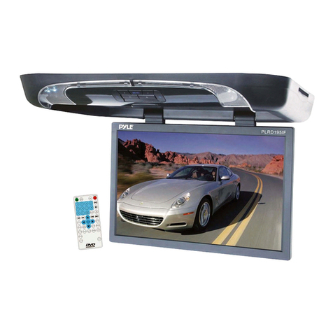
Pyle view
Pyle view PLRD195IF operating instructions

SecurView
SecurView SecurView SV-6922.LM.II installation instructions

Chrysler
Chrysler Uconnect 5.0 2015 Owner's manual supplement
Fujitsu Siemens Computers
Fujitsu Siemens Computers B17-2 Service manual
InCarTec
InCarTec 27-550 instruction manual
Innovative Technology
Innovative Technology ITIP-444 user manual
