Spelsberg Wallbox Pure User manual

safe.inspiring.green.
Product manual
Wallbox Pure/Wallbox Smart Pro
Wallbox Pure/Smart Pro

2
1. About these instructions . . . . . . . . . . . . . . . . . . . . . . . . . . . . . . . . . . . . . . . . . . . . . . . . . . . . . . . . . . . . . 4
1.1. Meaningofthesymbols.................................................................................................................................4
2. Safety instructions. . . . . . . . . . . . . . . . . . . . . . . . . . . . . . . . . . . . . . . . . . . . . . . . . . . . . . . . . . . . . . . . . . . 4
2.1. Generalsafety.................................................................................................................................................5
3. Intended readers . . . . . . . . . . . . . . . . . . . . . . . . . . . . . . . . . . . . . . . . . . . . . . . . . . . . . . . . . . . . . . . . . . . . 5
3.1. Operator..........................................................................................................................................................5
3.2. Qualifiedelectrician.......................................................................................................................................5
3.3. Tasks according to group............................................................................................................................... 5
4. Proper use . . . . . . . . . . . . . . . . . . . . . . . . . . . . . . . . . . . . . . . . . . . . . . . . . . . . . . . . . . . . . . . . . . . . . . . . . . 6
5. Scope of delivery. . . . . . . . . . . . . . . . . . . . . . . . . . . . . . . . . . . . . . . . . . . . . . . . . . . . . . . . . . . . . . . . . . . . 6
6. Accessories. . . . . . . . . . . . . . . . . . . . . . . . . . . . . . . . . . . . . . . . . . . . . . . . . . . . . . . . . . . . . . . . . . . . . . . . . . 7
7. Technical description. . . . . . . . . . . . . . . . . . . . . . . . . . . . . . . . . . . . . . . . . . . . . . . . . . . . . . . . . . . . . . . . . 7
7.1. Controlsandconnections...............................................................................................................................8
7.2. Nameplate.......................................................................................................................................................8
7.3. Cableentries...................................................................................................................................................9
8. Storage. . . . . . . . . . . . . . . . . . . . . . . . . . . . . . . . . . . . . . . . . . . . . . . . . . . . . . . . . . . . . . . . . . . . . . . . . . . . . 9
9. Installation. . . . . . . . . . . . . . . . . . . . . . . . . . . . . . . . . . . . . . . . . . . . . . . . . . . . . . . . . . . . . . . . . . . . . . . . . 10
9.1. Safety.............................................................................................................................................................10
9.2. Prerequisites..................................................................................................................................................10
9.3. Preparing for installation........................................................................................................................... 11
9.4. Checking the connectors............................................................................................................................ 12
9.5. Installation for wall mounting.................................................................................................................. 12
9.6. Connecting the charging cable....................................................................................................................15
9.7. Connectingthesupplycable........................................................................................................................16
9.8. Connecting the PV system signal line (optional, Wallbox Smart Pro only)................................................ 18
9.9. Connecting the LAN (optional, Wallbox Smart Pro only)........................................................................... 18
9.10. Necessary tests and measurements............................................................................................................ 18
9.10.1. Testing the insulation resistance................................................................................................................. 19
9.11. Initial commissioning................................................................................................................................. 19
9.12. Closing the enclosure cover......................................................................................................................... 19
10. Setup. . . . . . . . . . . . . . . . . . . . . . . . . . . . . . . . . . . . . . . . . . . . . . . . . . . . . . . . . . . . . . . . . . . . . . . . . . . . . . 20
10.1. Installing the Spelsberg wallbox app.......................................................................................................... 20
10.2. Instructions for installers on commissioning and configuring the wallbox via smartphone and NFC.... 21
10.3. Setting up the wallbox for the user/operator............................................................................................. 21
10.4. Setting the charging current...............................................................................................................22
10.5. Setting up the Wallbox Smart Pro in a network.........................................................................................22
10.5.1. Network connection via LAN....................................................................................................................... 22
10.5.2. NetworkconnectionviaWLAN....................................................................................................................23
Table of contents

3
10.6. Configuring applications (Smart Pro only).................................................................................................. 24
10.6.1. Configuringloadmanagement...................................................................................................................24
10.6.2. Energymanagementsystem........................................................................................................................24
10.6.3. OCPPbackend...............................................................................................................................................25
10.6.4. Parametrisinga PV system...........................................................................................................................25
11. Operation. . . . . . . . . . . . . . . . . . . . . . . . . . . . . . . . . . . . . . . . . . . . . . . . . . . . . . . . . . . . . . . . . . . . . . . . . . 25
11.1. StatusLEDandbuzzer..................................................................................................................................27
11.2. Chargingan electricvehicle......................................................................................................................... 28
11.3. Endingthechargingprocess........................................................................................................................29
11.4. Operation with the app............................................................................................................................... 29
11.4.1. Configuringchargingauthorisations..........................................................................................................30
11.4.2. TeachingRFIDchips......................................................................................................................................30
11.4.3. Viewingstatistics..........................................................................................................................................30
12. Cleaning. . . . . . . . . . . . . . . . . . . . . . . . . . . . . . . . . . . . . . . . . . . . . . . . . . . . . . . . . . . . . . . . . . . . . . . . . . . 30
13. Maintenance . . . . . . . . . . . . . . . . . . . . . . . . . . . . . . . . . . . . . . . . . . . . . . . . . . . . . . . . . . . . . . . . . . . . . . . 31
13.1. Updatingthefirmware................................................................................................................................31
13.1.1. Updatingthefirmware(offline)..................................................................................................................31
13.1.2. Firmware updates for a networked wallbox (online, Smart Pro only)...................................................... 31
14. Troubleshooting. . . . . . . . . . . . . . . . . . . . . . . . . . . . . . . . . . . . . . . . . . . . . . . . . . . . . . . . . . . . . . . . . . . . 32
14.1. Readingout faults(WallboxPure)............................................................................................................... 32
14.2. Reading out faults (Wallbox Smart Pro)...................................................................................................... 32
14.3. Unlocking the charging plug in an emergency........................................................................................... 32
15. Repair . . . . . . . . . . . . . . . . . . . . . . . . . . . . . . . . . . . . . . . . . . . . . . . . . . . . . . . . . . . . . . . . . . . . . . . . . . . . . 33
15.1. Safety.............................................................................................................................................................33
15.2. Contact/service:...........................................................................................................................................33
15.3. Genuinespareparts......................................................................................................................................33
15.4. Replacingthechargingcable.......................................................................................................................34
15.5. Replacing the design cover.......................................................................................................................... 34
15.5.1. Removingthedesigncover..........................................................................................................................34
15.5.2. Mountingthedesigncover..........................................................................................................................35
15.6. Replacing the cover retainer........................................................................................................................36
16. Warranty. . . . . . . . . . . . . . . . . . . . . . . . . . . . . . . . . . . . . . . . . . . . . . . . . . . . . . . . . . . . . . . . . . . . . . . . . . . 35
17. Deinstallation. . . . . . . . . . . . . . . . . . . . . . . . . . . . . . . . . . . . . . . . . . . . . . . . . . . . . . . . . . . . . . . . . . . . . . 37
18. Disposal . . . . . . . . . . . . . . . . . . . . . . . . . . . . . . . . . . . . . . . . . . . . . . . . . . . . . . . . . . . . . . . . . . . . . . . . . . . 37
19. Technical data. . . . . . . . . . . . . . . . . . . . . . . . . . . . . . . . . . . . . . . . . . . . . . . . . . . . . . . . . . . . . . . . . . . . . . 38

4
1. About these instructions
Read these instructions carefully before assembly and operation and keep them in a safe place. Give them to
the new user if the product is passed on. More information on the product, details and technical knowledge
can be found on our website.
1.1. Meaning of the symbols
Gefahr
Failure to comply will result in death or serious injury.
►Avoid the danger.
Warnung
Failure to comply may result in death or serious injury.
►Avoid the danger.
Vorsicht
Failure to comply may result in injury.
►Avoid the danger.
Achtung
Failure to comply may result in damage to property.
►Avoid the damage.
Note
Explanatory note
Important additional information.
2. Safety instructions
The operator is responsible for ensuring that the wallbox is always kept in a proper and safe condition and
must check it at regular intervals (See 13. Maintenance, page 29).
The manufacturer is not liable for damage resulting from improper use, e.g.:
Assembly or connection errors
Damage to the product due to mechanical effects and incorrect connection voltage
Modifications to the product without the express permission of the manufacturer
Use for purposes other than those described in the manual

5
2.1. General safety
Warnung
Risk of fatal electric shock
►If the wallbox or the connected cables are visibly damaged, take the wallbox out of
operation.
►If the connected cables and lines of the wallbox are damaged, have them replaced by a
qualified specialist company to avoid hazards.
►Always pull the charging cable from the vehicle inlet by the plug or by the optional plug
holder accessory, never by the cable.
►Never immerse the vehicle charging plug in liquids.
Warnung
Health hazard
►Do not operate the wallbox at outside temperatures below -25 °C or above +40 °C.
►Do not unfasten the cover of the wallbox in the event of a fire. Use extinguishing agents
approved for electronic devices. Do not use water for extinguishing.
►This device can be used by children aged 8 years or more and by persons with reduced
physical, sensory or mental capabilities or lack of experience and knowledge, provided that
they are supervised or have been instructed on using the device safely and they understand
the hazards involved.
►Children must not be allowed to play with the device.
►Cleaning and operator maintenance must not be performed by children without
supervision.
3. Intended readers
3.1. Operator
As the operator, you are responsible for the device. You are responsible for the proper use and safe
operation of the device. This also includes instructing persons who use the device.
As an operator without specialised electrical training, you may only perform tasks that do not have to be
done by a qualified electrician.
3.2. Qualified electrician
A qualified electrician is someone with a recognised electrotechnical training qualification. Based on this
expertise, they are authorised to perform the electrotechnical work specified in these instructions.
Requirements for a qualified electrician:
Knowledge of general and special safety and accident prevention regulations.
Knowledge of the electrotechnical regulations
Knowledge of national regulations
The ability to recognise risks and avoid possible hazards.
6
3.3. Tasks according to group
Operator
Operation
Cleaning
Compliance with maintenance intervals
Troubleshooting
Qualified electrician
Installation
Initial commissioning
Maintenance
Decommissioning
4. Proper use
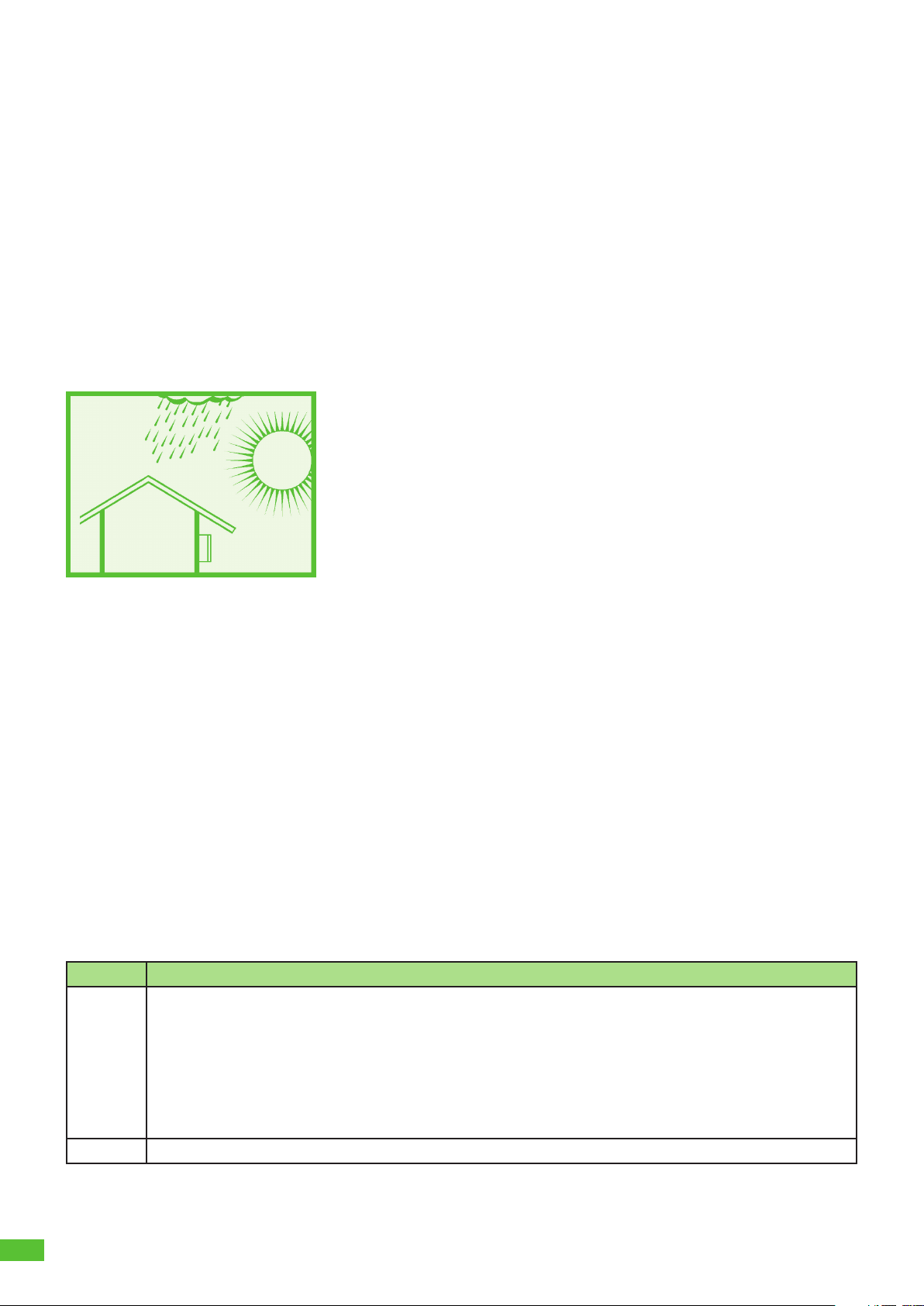
Fig. 1: Installation in a protected outdoor area
The wallbox is designed for charging electric vehicles with a type 2 connection using alternating current. The
wallbox is permanently connected to the AC mains.
The wallbox is suitable for indoor and outdoor use. The wallbox is intended for mounting on a wall or
pedestal. Only pedestals provided by Spelsberg may be used for mounting.
The wallbox must be operated in accordance with the applicable international and national regulations.
The following international regulations and national implementations must be observed:
IEC 61851-1
IEC 62196-1
IEC 60364-7-722
IEC 61439-7
The wallbox can be used in areas with unrestricted access. The wallbox is intended for private use only. Any
other use is inappropriate.
5. Scope of delivery
Quantity Description
1 Pre-assembled wallbox consisting of:
Box with integrated cable management
Cover
Cover screws
Cover retainer
3x double membrane seals DMS M25 for cable entries
Strain relief clamp for the charging cable
1 Mounting rail

7
Quantity Description
1 Charging cable with type 2 plug
1 Design cover
5 Disc for unlocking the design cover
3 RFID chip
4 Truss head screw 6x60
4 Wall plug UX 8 x 50 R
3 Double membrane seal cable entry DMS M16
1 Double membrane seal cable entry DMS M25
1 Double membrane seal cable entry DMS M32
3 Setup QR code for commissioning by app
1 Quick Start Guide
1 Installation Guide
6. Accessories
Description Order number
Polar RFID chip 591 813 01
Graphite RFID chip 591 814 01
Other accessories can be found on the Spelsberg website.
7. Technical description
The wallbox provides the AC voltage for single-phase or three-phase charging of electric vehicles (charging
mode 3, connection case C according to IEC 61851). As soon as the charging cable is connected to the electric
vehicle, the charging process can begin.
Note
State D (ventilation) is not supported.
Depending on the setting in the wallbox, charging may have to be authorised by the user before it begins.
After charging, the permanently connected charging cable can be stored using the cable management of the
wallbox. The protective cap prevents moisture from entering the charging plug.
A status LED and a buzzer signal the states of the wallbox and the charging process.
The wallbox switches off the voltage in the following situations:
DC fault currents above 6 mA
Excessive temperature
Overload (Smart Pro only)
Overvoltage / undervoltage (Smart Pro only)
The Spelsberg wallbox app helps the installer to configure the wallbox and offers the operator and users a
variety of functions for controlling the wallbox and analysing the charging processes:
Charging electric vehicles by providing the AC voltage
Registration of RFID chips
Communication with the vehicle as per ISO-15118 (Plug & Charge, Smart Pro wallbox only)
Intelligent load management for operation in a charging network (Smart Pro wallbox only)
Integration into energy management systems (Smart Pro wallbox only)
Integration into photovoltaic (PV) charging systems (Smart Pro wallbox only)
Evaluation of charging processes (Smart Pro wallbox only)
8
The Smart Pro wallbox can be connected to the internet using the following options:
LAN (standard)
WLAN
7.1. Controls and connections
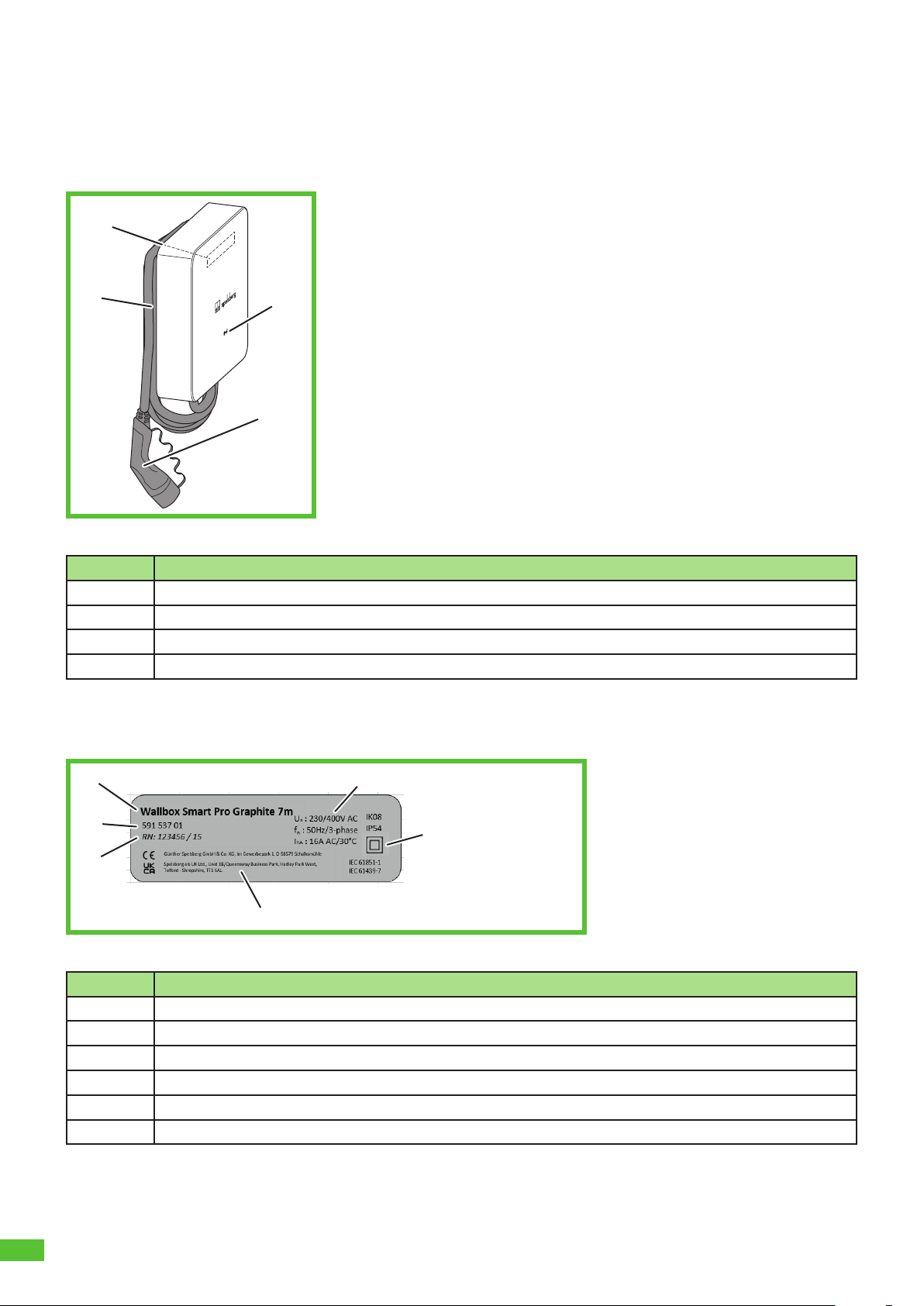
Fig. 2: General view
Item Description
1Nameplate (under the design cover)
2Status LED, buzzer and RFID reader
3Charging cable
4Cable management
7.2. Nameplate
Fig. 3: Nameplate
Pos. Description
1designation of the wall box
2technical specifications
3protection class
4manufacturer address
5serial number
6item number
4
1
2
3
6
5
1
4
2
3
9
7.3. Cable entries
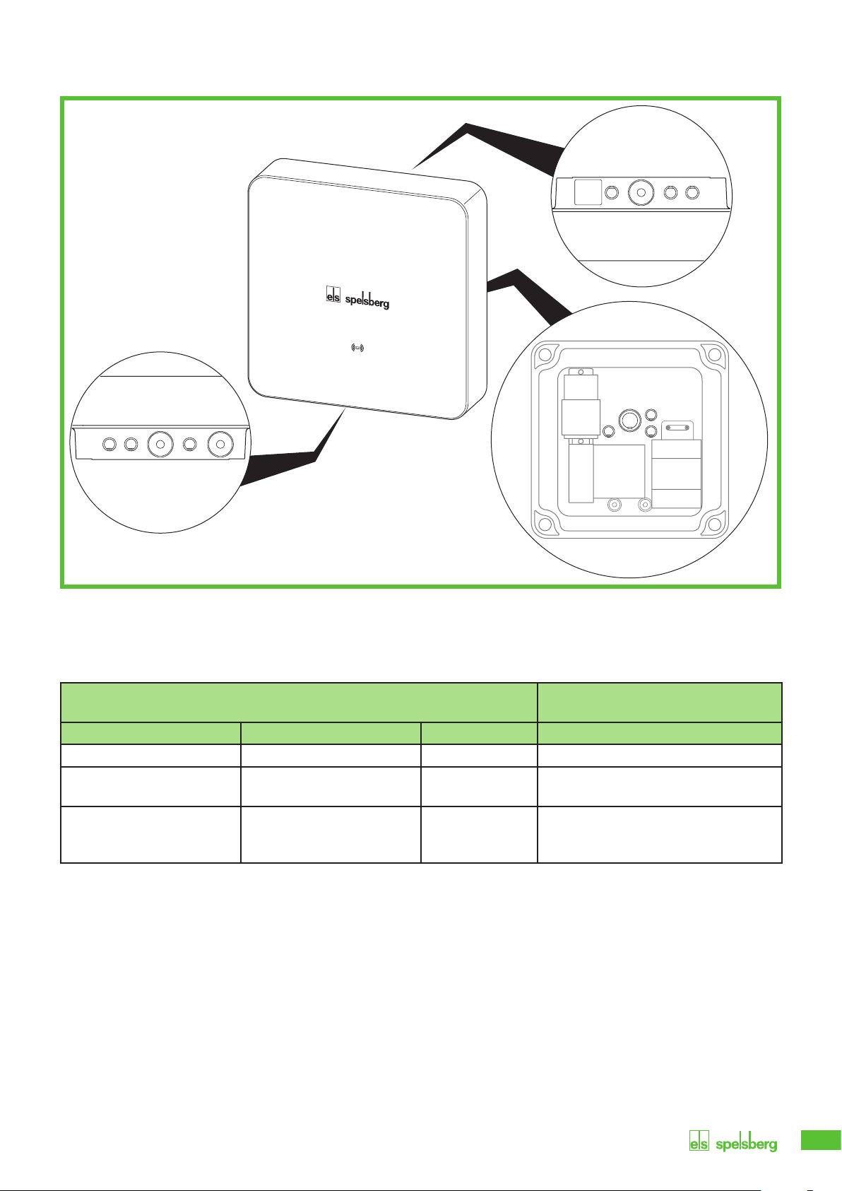
Fig. 4: Knockouts and factory installed cable entries DMS in the enclosure
The wallbox has a number of cable entries. Some of the cable entries are equipped with double membrane
seals (DMS). The remaining cable entries are designed as knock-out membranes and can be opened if
necessary. The wallbox has the following cable entries and knockouts:
Knockouts Suitable double membrane seals
(DMS)
Top Bottom Rear Sealing area (size)
3x M16 3x M16 3x M16 5 – 9 mm (M16)
1x M25/32
equipped with DMS M25
1x M25/32
equipped with DMS M25
1x M25/32 9 – 16 mm (M25) /
14 – 21 mm (M32)
1x M25
for the charging cable,
equipped with DMS M25
9 – 16 mm (M25)
8. Storage
►Keep the device as well as the charging cable and accessories in a dry and clean place before installation.

10
9. Installation
9.1. Safety
Vorsicht
Risk of injury
Users can be injured by damaged components.
►Do not install the charging station:
– Near flammable materials
– In areas with explosion hazards
– In salty or wet environments
– In the vicinity of aggressive vapours
– In environments subject to constant vibration
Examples of these environments of include petrol station forecourts, chemical plants, waste
disposal sites and sewage plants.
Achtung
Risk of damage due to weather conditions
Incorrect choice of location can damage the charging station.
►Do not expose the charging station to any heat sources (such as sunlight or heaters).
►Install the charging station in a location protected from rain and splashing water (for
example, in a protected outdoor area, Fig. 1).
Risk of damage from drilling
Damage can be caused by badly executed drilling.
►Before drilling holes in the wall or mounting surface, make sure that this will not damage
any electrical cables or other lines.
9.2. Prerequisites
The following equipment must be provided on site to protect the wallbox:
Pre-fuse with a maximum rating of 16 A. The manufacturer recommends:
• 230 V: Miniature circuit breaker (C characteristic); 1-pole
• 400 V: Miniature circuit breaker (C characteristic); 3-pole
Residual current device RCD Type A with IΔn≤30 mA
• 230 V: Residual current circuit breaker, 2-pole
• 400 V: Residual current circuit breaker, 4-pole
Depending on the installation location: Overvoltage protection device according to national and regional
regulations.
Observe the following when choosing the installation location:
Always mount the wallbox upright (e.g. on building walls).
The mounting surface must be level and sufficiently strong. If there is unevenness on the wall of more
than 2 mm, compensation is required under the mounting points to prevent the enclosures from
warping.
The fastening material used must be suitable for the mounting surface.
There must be at least 250 mm free space around the wallbox. This includes plant growth.
Spelsberg recommends keeping a sufficient distance to other obstacles in the installation area.
The bottom of the wallbox must be at least 900 mm above the ground.
The wallbox must always be sufficiently lit during operation. Install lighting if necessary.
11
You will need the following tools for installation:
Electric drill
Screwdrivers (suitable for the fastening screws and cover screws)
Spirit level
Pencil
Side cutter
Wire stripper
Crimping tool
9.3. Preparing for installation
►Only for cable entry through the back wall: Unscrew the enclosure cover from the wallbox.
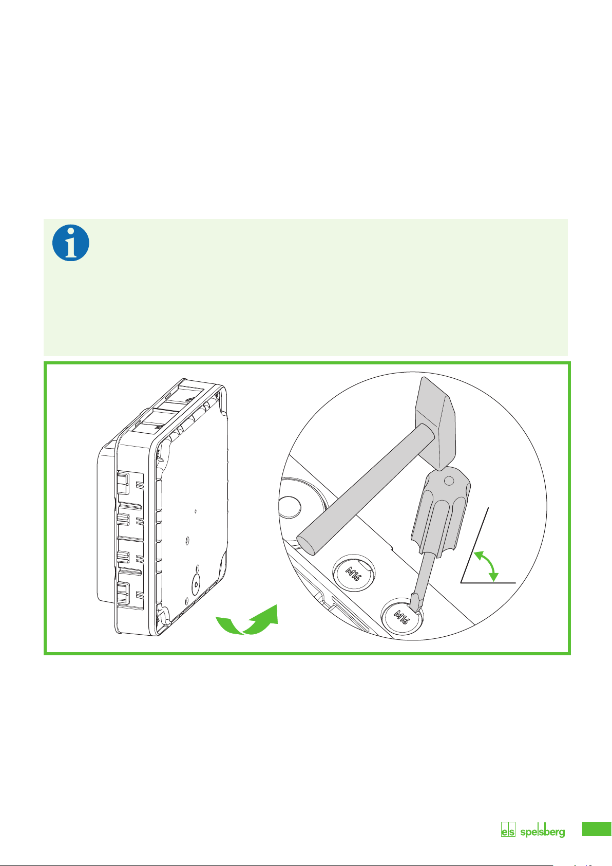
Note
The cable entry for the charging cable has a DMS (bottom right of the wallbox). For the power
supply, there are double membrane seals on the top and bottom of the wallbox. Knockouts
only have to be opened if additional cables are to be connected or the supply cable is to be fed
into the wallbox from the rear.
If the diameter of the supply cable is too big for the sealing area of the pre-installed DMS M25:
►Remove the DMS M32.
►Open the appropriate knockout.
►Install an DMS M32.
Fig. 5: Opening the knockout at the bottom
►Open the required knockouts from the enclosure.
►Fit the appropriate double membrane seals.
60 − 75°

12
9.4. Checking the connectors
Fig. 6: Charge controller connections
Item Description Item Description
1 Connection for plug A (PE, CP, ...) 6 Connection for measuring current transformer
2 Connection for LAN (LAN-2, Smart Pro only) 7 Connection for 2-phase disconnection (Smart
Pro only)
3 Connection for LAN (LAN-1, Smart Pro only) 8 Connection for PV enabling contact (Smart Pro
only)
4 2x USB type A (HMI board connection) 9 Connection for contactor control
5 1x USB type B (service port) 10 Connection for supply voltage
►Check that all connectors are firmly fitted.
9.5. Installation for wall mounting
Note
Wall plugs and screws are included in the scope of delivery.
►Use screws with a flat head (not countersunk screws).
To fasten the wallbox you will need:
4 screws (maximum diameter 6 mm, screw head diameter at least Ø 12 mm, maximum Ø 15 mm).
4 suitable wall plugs
Fig. 7: Dimensional drawing for cable entry through the back wall (scale 1:2)
►Only for cable entry through the back wall: Use the dimensional drawing to mark the fastening points of
the mounting rail (Fig. 7).
1
2
3
4
5
10
9
8
7
6
150
40
32
56
3131

13
Fig. 8: Marking the fastening points for the mounting rail
►Mark the fastening points for the mounting rail (Fig. 8).
►Drill the holes for the fastening points.
►Insert the wall plugs into the holes.
►Screw on the mounting rail.
Fig. 9: Marking the fastening points for the wallbox
►Centre the wallbox on the mounting rail (1.).
►Mark the fastening points for the wallbox (2.).
►Only for cable entry through the base: Mark the cable entries.
►Take the wallbox off the mounting rail.
150 mm
1.
2.

14
Fig. 10: Drilling holes for the fastening points
►Drill the holes for the fastening points.
►Insert the wall plugs into the holes.
►Only for cable entry through the base: Lay the required cables (e.g. power supply, LAN cable).
►Connect the charging cable (see “9.6. Connecting the charging cable”, page 15).
►Only for cable entry through the base: Push the required cables through the appropriate cable entries in
the base of the wallbox.
Fig. 11: Screwing on the wallbox
►Place the wallbox centrally on the mounting rail.
►Screw the wallbox tight with the 2 screws.
15
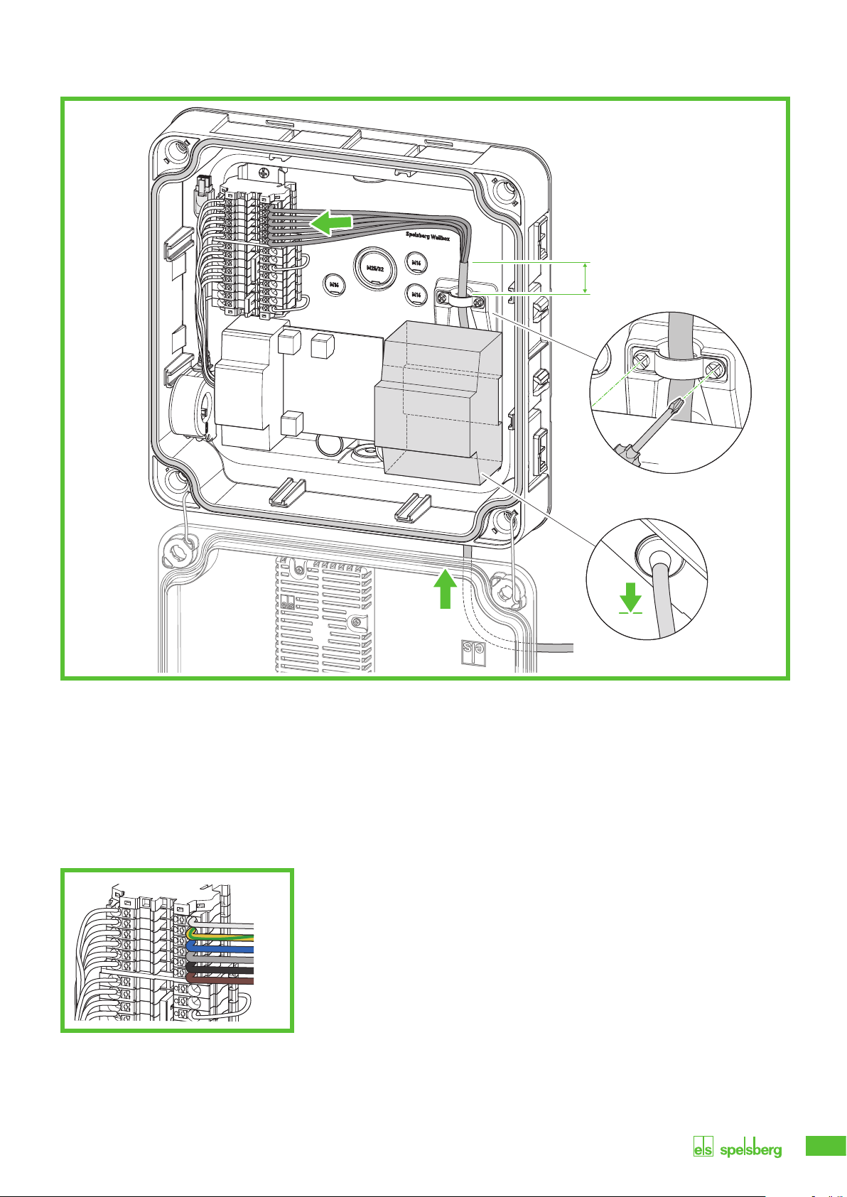
9.6. Connecting the charging cable
Fig. 12: Connecting the charging
cable
►Unfasten the strain relief.
►Feed the charging cable through the bottom right DMS M25 and the strain relief clamp.
►Pull the charging cable back slightly so that the DMS forms a downward funnel. The sheath of the cable
must still protrude at least 1 cm from the strain relief.
►Tighten the strain relief (tightening torque: 0.9 Nm).
►Make sure that the charging cable cannot be pulled out of the strain relief.
Fig. 13: Connecting the charging cable
►Connect the charging cable (Fig. 13).
2.
1.
>1 cm
3.
4.
PE
CP
N
L3
L2
L1
16
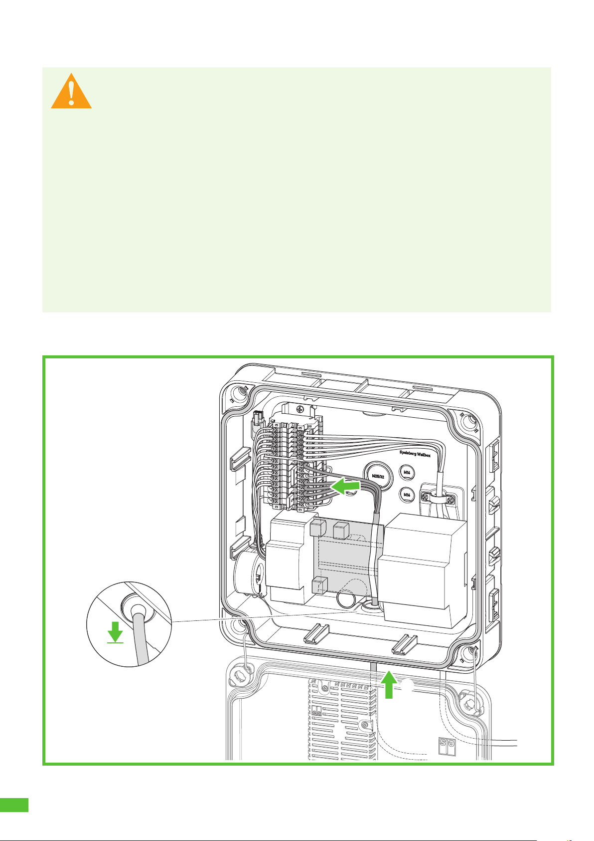
9.7. Connecting the supply cable
Warnung
Risk of fatal electric shock
There is a risk of electrocution if the electrical supply cable is not properly connected.
►Always have the electrical supply cable connected by a locally authorised electrician.
►Install a suitable residual current circuit breaker and line fuse in the supply line.
►Observe the following safety rules before any work on electrical components:
– Disconnect the power supply.
– Secure it against being switched on again.
– Check that all poles are de-energised.
– Earth and short-circuit.
– Cover or enclose adjacent live parts.
►Observe the local regulations and laws.
►Before connecting, make sure that the supply line, plugs and connection sockets are clean
and dry.
►Never touch the plugs if your hands are wet or you are standing in water.
►Take care not to damage the cables and lines when connecting the supply line and LAN
cable.
Use a supply cable with the maximum cross-section of the connection terminal: rigid and flexible 6 mm2,
flexible with 4 mm2ferrule.
Fig. 14: Connecting the supply cable
2.
3.
1.
17
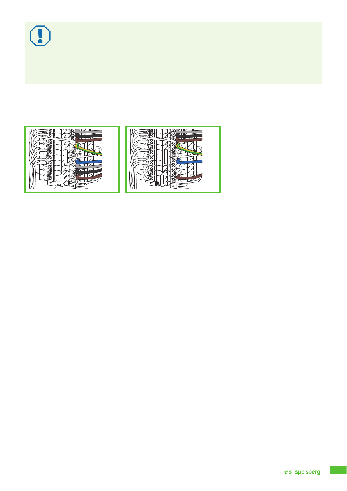
Achtung
Risk of damage to the wallbox
Incorrect wiring can damage the wallbox.
►Ensure a clockwise rotating magnetic field for a 400 V power supply.
►For a 1-phase wallbox, always connect the 230 V power supply to L1.
►If you are operating several 1-phase wallboxes in a charging network, make sure the load is
distributed evenly over the different phases to avoid imbalances.
►Feed the supply cable through the required DMS.
►Pull the supply cable back so that the DMS forms a funnel away from the enclosure.
►Strip the wires of the supply cable to 10–12 mm.
Fig. 15: 3-phase connection of
the supply cable (400 V)
Fig. 16: 1-phase connection of
the supply cable (230 V)
►Connect the wires as follows:
• L1 – brown
• L2 – black (400 V connection only)
• L3 – grey (400 V connection only)
• N – blue
• PE – green/yellow
PE
N
L1
L3
L2
PE
N
L1

18
9.8. Connecting the PV system signal line (optional, Smart Pro
wallbox only)
Fig. 17: Connecting the PV system signal line
To connect a PV enabling contact on the photovoltaic system side, a potential-free contact (relay, normally
open contact) is required. Use an unshielded 2 x 0.75 mm2control cable.
►Feed the PV cable through the required DMS.
►Pull the PV cable back so that the DMS forms a funnel away from the enclosure.
►Strip 8 – 10 mm of the cable.
►Place the cable on the spring terminals.
Note
The connection of the inverter of the photovoltaic system to the wallbox must be parametrised
in the Spelsberg wallbox app (See 10.6.4. Parametrising a PV system, page 24).
9.9. Connecting the LAN (optional, Smart Pro wallbox only)
Achtung
Risk of damage to the LAN cable
If the LAN cable is bent too much, it may be damaged and the function may be restricted.
►Observe the bending radii of the LAN cable used.
►Feed the LAN cable through the required DMS. Use a LAN cable of category 6 or 7 (Cat 6 or Cat 7).
►Pull the LAN cable back so that the DMS forms a funnel away from the enclosure.
►Crimp an RJ45 connector onto the LAN cable.
►Connect the LAN cable to the LAN-1 socket in the cover (Fig. 6, 3).
►Tie the LAN cable onto the existing wiring harness to the cover.
9.10. Necessary tests and measurementsn
►Switch on the supply voltage.
►Before initial commissioning, check and record whether the protective measures of the system function in
accordance with the nationally applicable regulations, including:
• Continuity of the connections of the protective conductor
• Insulation resistance (with the controller and measuring devices (meters) disconnected)
• Residual current circuit breaker
• Tripping current
• Tripping time
►Give the test report and the handover report to the operator of the system.
PV1 PV2
19
9.10.1. Testing the insulation resistance
►Disconnect the following plugs and cables inside the wallbox:
• Contactor control connection on the charge controller (Fig. 6, 9)
• Supply voltage connection on the charge controller (Fig. 6, 10)
• Smart Pro wallbox only: N conductor on the MID meter (terminal 10).
►Test the insulation resistance.
►Make the connections again.
►Check that all connectors are firmly fitted.
9.11. Initial commissioning
►Check the connections.
►Apply the supply voltage by switching on the fuse.
►Check the voltage and the rotating magnetic field.
►Close the enclosure cover (See 9.12. Closing the enclosure cover, page 19).
►Continue with the setup (See 10. Setup, page 20).
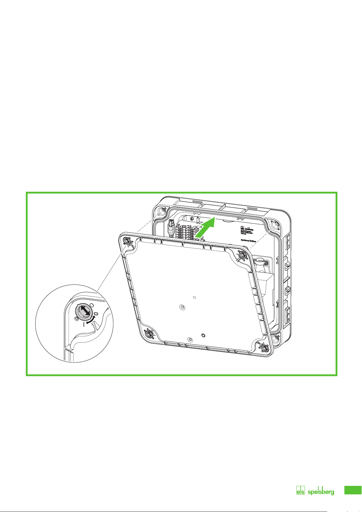
9.12. Closing the enclosure cover
Fig. 18: Closing the enclosure cover
►Close the enclosure cover. Make sure that the cables are not pinched.
►Turn the catches in the enclosure cover of the wallbox a quarter turn clockwise until you feel them
engage.
►Attach the design cover (See 15.5.3. mounting the design cover, page 34).

20
10. Setup
Note
Under the following conditions, the wallbox does not need to be set up via smartphone:
– 3-phase connection type
– Domestic connection and supply line set up for 16 A
– Autonomous operation without load management, connection to energy management
systems or PV systems
Spelsberg recommends commissioning via smartphone for the purposes of documentation and
handover.
Note
Several identical setup QR codes are provided for the commissioning app. These contain
sensitive access data.
►Keep the setup QR codes in a safe place. Stick the setup QR codes in the manual or onto
the invoice, for example.
►Do not affix the setup QR code to the wallbox or anywhere it can be seen from the outside.
10.1. Installing the Spelsberg wallbox app
An NFC-capable smartphone is required for initial setup via smartphone.
Prerequisites:
Android version 6 or higher - API level 23, e.g. Samsung Galaxy A6 or newer.
iOS version iOS 13 or higher, e.g. iPhone 7 or newer.
►Download the Spelsberg wallbox app from the Play Store or App Store and install it on the smartphone.
Alternatively, use the following QR code link to access the app:
spelsberg.com/wallbox/app/
Other manuals for Wallbox Pure
1
This manual suits for next models
1
Table of contents
Popular Automobile Accessories manuals by other brands


SAF-HOLLAND
SAF-HOLLAND NoLube FW31 Series Installation, Operation, Maintenance and Troubleshooting

Lund
Lund Genesis installation instructions

Needit
Needit Park Micro 2 quick guide

Mityvac
Mityvac 7300 user manual

KeriSystems
KeriSystems V-Track installation guide

Silvercrest
Silvercrest SBF 2 B2 operating instructions

iCell
iCell S550 quick start guide

MRHANDSFREE
MRHANDSFREE BLUE PERFECTION User instructions

pro user
pro user JADE Assembly instruction and safety regulations

Caraudio-Systems
Caraudio-Systems r.LiNK RL-PCM3-TF manual

Purpleline
Purpleline Nemesis Ultra FNU100 user manual

NAV TOOL
NAV TOOL NAVRGB6.0-VI+MBCIRC installation manual