RUD VLBS-U-LT User manual

1
VLBS-U-LT
RUD Ketten
Rieger & Dietz GmbH u. Co. KG
D-73428 Aalen
Tel. +49 7361 504-1370
Fax +49 7361 504-1171
www.rud.com
RUD-Art.-Nr.: 7903754-EN / V02 09.021
> VLBS-U-LT <
(for low temperatures)
Safety instructions
This safety instruction/declaration of Conformity must be kept for
the entire time usage time and forwarded with the product.
- Translation of the Original instructions -
EG-Konformitätserklärung
entsprechend der EG-Maschinenrichtlinie 2006/42/EG, Anhang II A und ihren Änderungen
Hersteller:
RUD Ketten
Rieger & Dietz GmbH u. Co. KG
Friedensinsel
73432 Aalen
Hiermit erklären wir, dass die nachfolgend bezeichnete Maschine aufgrund ihrer Konzipie-
rung und Bauart, sowie in der von uns in Verkehr gebrachten Ausführung, den grundle-
genden Sicherheits- und Gesundheitsanforderungen der EG-Maschinenrichtlinie
2006/42/EG sowie den unten aufgeführten harmonisierten und nationalen Normen sowie
technischen Spezifikationen entspricht.
Bei einer nicht mit uns abgestimmten Änderung der Maschine verliert diese Erklärung ihre
Gültigkeit.
Produktbezeichnung: Lastbock VLBS-LT
_____________________________________________
_____________________________________________
Folgende harmonisierten Normen wurden angewandt:
DIN EN 1677-1 : 2009-03 DIN EN ISO 12100 : 2011-03
_________________ _________________
_________________ _________________
_________________ _________________
_________________ _________________
_________________ _________________
Folgende nationalen Normen und technische Spezifikationen wurden außerdem angewandt:
BGR 500, KAP2.8 : 2008-04
_________________ _________________
_________________ _________________
_________________ _________________
_________________ _________________
_________________ _________________
Für die Zusammenstellung der Konformitätsdokumentation bevollmächtigte Person:
Michael Betzler, RUD Ketten, 73432 Aalen
Aalen, den 26.09.2016
Dr.-Ing. Arne Kriegsmann,(Prokurist/QMB)
_____________________________________________
Name, Funktion und Unterschrift Verantwortlicher
EC-Declaration of conformity
According to the EC-Machinery Directive 2006/42/EC, annex II A and amendments
Manufacturer:
RUD Ketten
Rieger & Dietz GmbH u. Co. KG
Friedensinsel
73432 Aalen
We hereby declare that the equipment sold by us because of its design and construction,
as mentioned below, corresponds to the appropriate, basic requirements of safety and
health of the corresponding EC-Machinery Directive 2006/42/EC as well as to the below
mentioned harmonized and national norms as well as technical specifications.
In case of any modification of the equipment, not being agreed upon with us, this declara-
tion becomes invalid.
Product name:
Load ring VLBS-LT
_____________________________________________
_____________________________________________
The following harmonized norms were applied:
DIN EN 1677-1 : 2009-03 DIN EN ISO 12100 : 2011-03
_________________ _________________
_________________ _________________
_________________ _________________
_________________ _________________
_________________ _________________
The following national norms and technical specifications were applied:
BGR 500, KAP2.8 : 2008-04
_________________ _________________
_________________ _________________
_________________ _________________
_________________ _________________
_________________ _________________
Authorized person for the configuration of the declaration documents:
Michael Betzler, RUD Ketten, 73432 Aalen
Aalen, den 26.09.2016 Dr.-Ing. Arne Kriegsmann,(Prokurist/QMB)
_____________________________________________
Name, function and signature of the responsible person
Load ring - for welding
for low temperatures
VLBS-U-LT
EN

2VLBS-U-LT
This user manual contains information about
the correct and safe use of VLBS-U-LT.
Read the user manual carefully and in full
before using the RUD lifting point VLBS-U-
LT. Ensure that you have understood all the
contents. If you need further information,
ask your RUD retailer or RUD application
engineer.
Non-observation of the instructions can
lead to injuries or damage and will invali-
date the guarantee.
If doubtful or misunderstanding the German
version of this document is crucial.
1 Safety instructions
ATTENTION
Wrong assembled or damaged lifting points
as well as impropriate use can lead to
injuries of persons and property damage
when loads falls.
Inspect all lifting points before each use
carefully!
• Withdraw all body parts (ngers, hands, arms etc.)
from the danger zone during the lifting process (risk
of squeezing).
• The RUD lifting points VLBS-U-LT must only be
used by competent and designated persons which
have been trained and taking into account the DGUV
109-017, and outside Germany by respecting the
country specic regulations.
• Do not exceed the working load limit (WLL) indi-
cated on the lifting point.
• No technical alterations must be implemented on
the VLBS-U-LT.
• No persons are allowed in the danger zone.
• Staying below suspended loads is prohibited.
• Jerky lifting (strong impacts) should be prevented.
• Always ensure a stable position of the load when
lifting. Swinging must be prevented.
• Damaged or worn VLBS-U-LT must not be used.
2 Intended use
• The RUD VLBS-U-LT lifting point must only be used
for the assembly at loads or lifting means.
• The VLBS-U-LT is for the attaching of loads.
• The RUD lifting points can also be used as lashing
points for the attachment of lashing means.
• RUD lifting points must only be used for the inten-
ded described usage.
3 Assembly and user instruction
3.1 General information
• Capability of temperature usage:
RUD lifting points VLBS-U-LT are suitable for the
temperature range from -45°C up to 400°C. When
used in temperatures higher than 200°C, the WLL
of the lifting point must be reduced as follows:
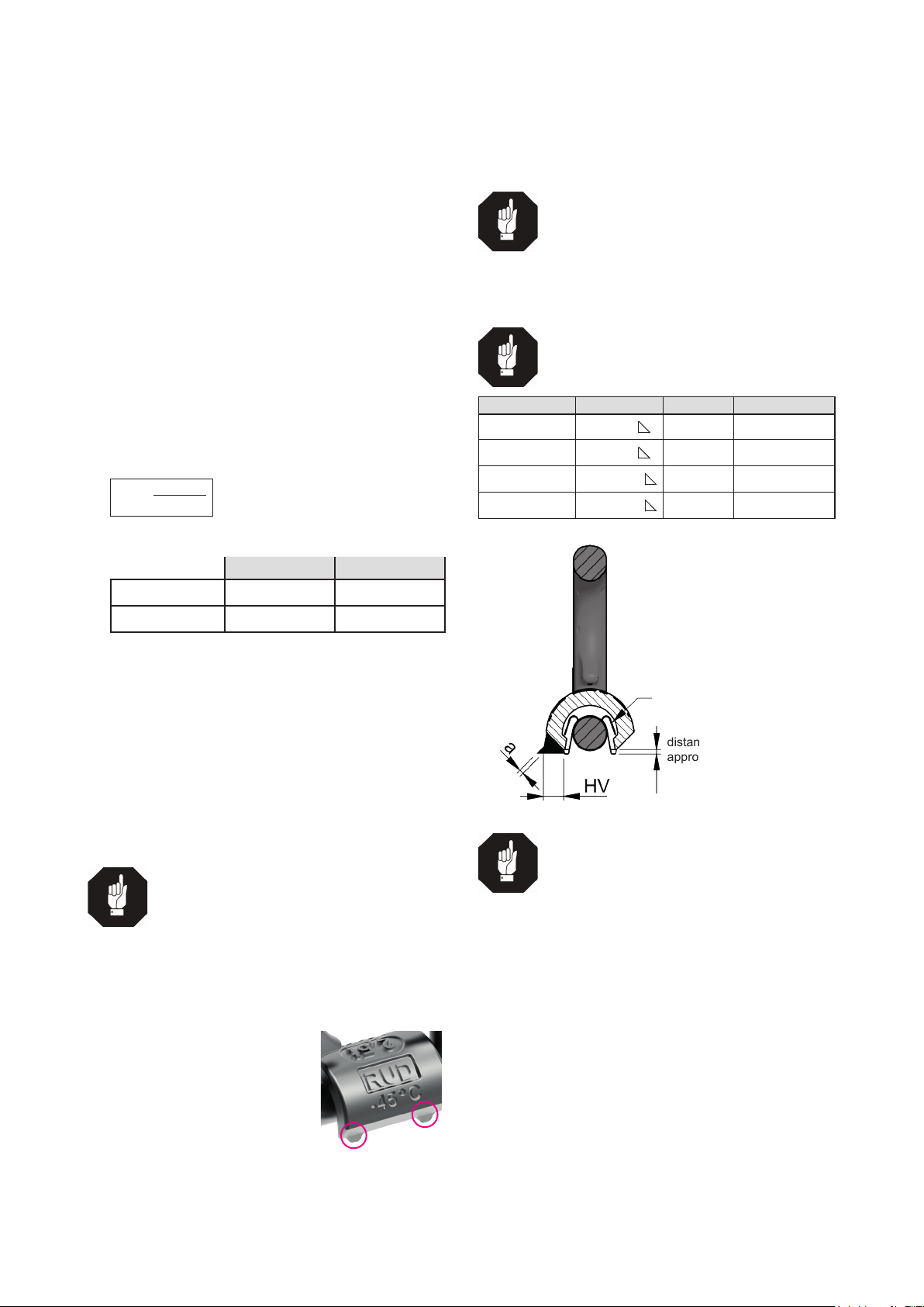
-45°C up to 200°C no reduction
200°C up to 300°C minus 10 %
300°C up to 400°C minus 25 %
Temperatures higher than 400°C are prohibited!
HINT
The VLBS-U-LT can be recognized by the
additional marking (-45°C) at the weld-on
block.
HINT
VLBS-U-LT lifting points can be stress-
relieved one-time together with the load (f.e.
as part of a welding construction), when
unloaded, one-time stress relieved.
(Temperature <600°C /1100°F - max. 1 hour)
Ability verification of the used welding
material must be determined with the cor-
responding supplier of electrodes resp.
welding ller manufacturer.
Impact energy >= 27 Joule at -45°C
• RUD lifting points VLBS-U-LT must not be used
in combination with aggressive chemicals (acids,
alkaline solutions and vapours).
• The places where the lifting points are xed should
be marked with colour
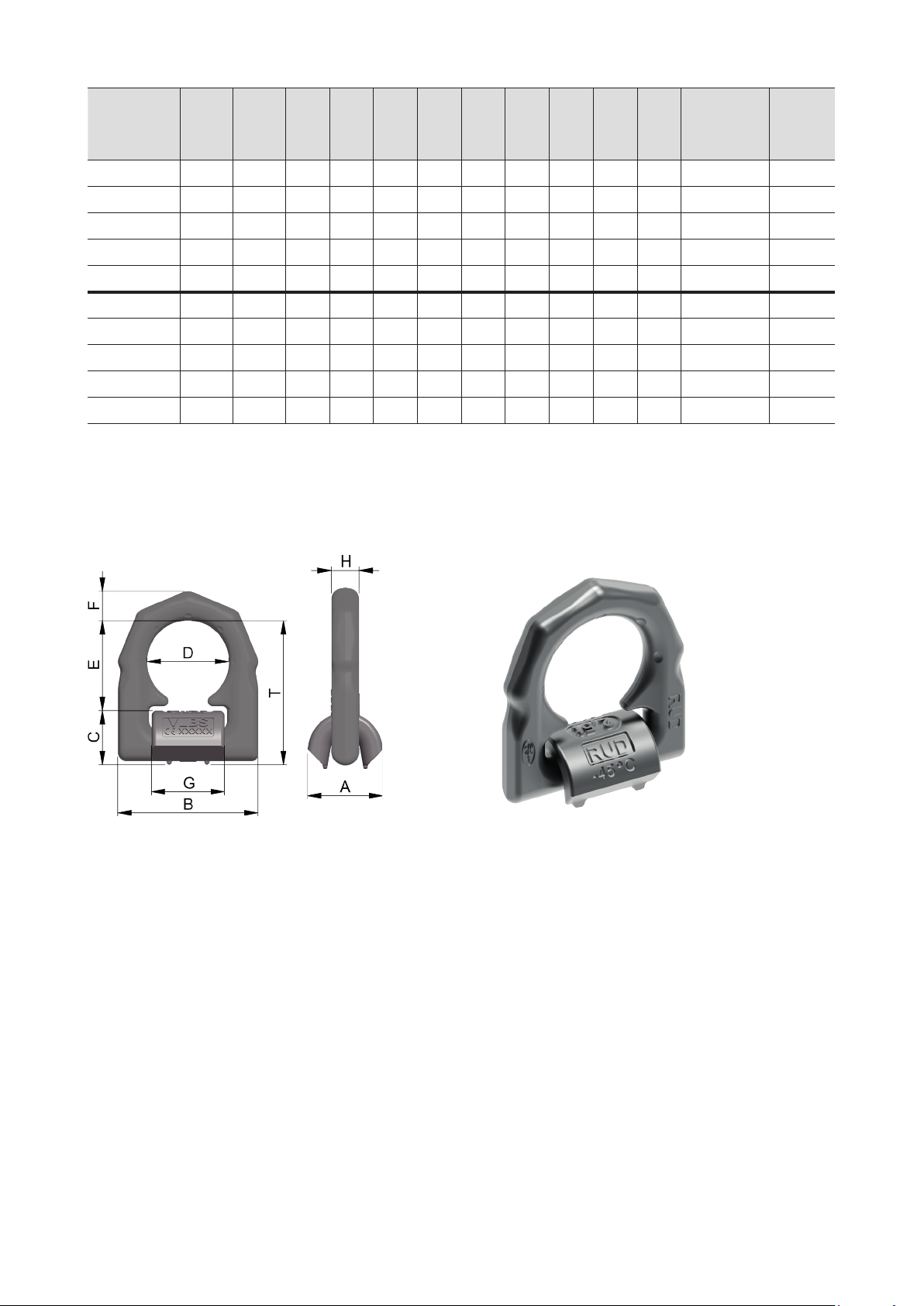
• The VLBS-U-LT has a protect on the inside po-
sitioned spring, which holds the load ring in the
desired position.
• The parts of the VLBS-U-LT are connected captive
and will be supplied assembled as a complete unit.
3.2 Hints for the assembly
Basically essential:
• The material construction to which the lifting point
will be attached should be of adequate strength to
withstand forces during lifting without deformation.
CONTENT
1 Safety instructions 2
2 Intended use 2
3 Assembly and user instruction 2
3.1 General information ..................................................2
3.2 Hints for the assembly ..............................................2
3.3 Hints for the welding .................................................3
3.4 Hints for the usage ...................................................4
4 Inspection / repair / disposal 4
4.1 Hints for periodical inspections.................................4
4.2 Test criteria for the regular visual inspection by the
user...........................................................................4
4.3 Additional test criteria for the
competent person / repair worker.............................4
4.4 Disposal....................................................................4

3
VLBS-U-LT
The weld-on material must be suitable for welding
and the contact areas must be free from impurities,
oil, colour, etc. The material of the forged welding
block is: S355J2 (1.0577), DIN EN 10025-2
• The lifting points must be positioned on the load in
such a way that movement is avoided during lifting:
• For single leg lifts: the load ring should be
positioned vertically above the centre of gravity
of the load.
• For two leg lifts: the lifting points must be
equidistant to/or above the centre of gravity
of the load.
• For three and four leg lifts: the lifting points
should be arranged symmetrically around the
centre of gravity in the same plane, if possible.
• Load Symmetry:
Determine the working load limit of each individual
RUD lifting point for symmetrical and unsymme-
trical loading according to the following physical
formula:
WLL = working load limit / single strand (kg)
G = Weight of load (kg)
n = Number of load bearing strands
ß = Inclination angle of single strand
WLL=G
n x cos ß
Number of load bearing strands:
Symmetrical Unsymmetrical
two leg 2 1
three / four leg 3 1
Table 1: Load bearing strands (see table 3)
• Finally check correct assembly (see section 4
Inspection / repair / disposal).
3.3 Hints for the welding
The welding should only be carried out according to
ISO 9606-1 orAWS Standards by an authorized welder.
Verications of suitability of the used weld-on mate-
rial must be checked with the supplier of the welding
electrodes.
HINTS
• Please note the corresponding user hint
in regard of the welding ller materials
(see Table 4).
• All weld seams must be carried out with
the same temperature.
• Do not weld at the heat treated load ring.
•
The distance lugs assist in achieving the
correct root weld (ap-
prox. 3 mm = 0.1 inch).
They may not be remo-
ved.
Pic. 1: distance lugs
1 Start tacking at the center of the weld-on block.
2 Check function of the suspension ring (must be able
to pivot 180°). If necessary please correct.
3 Weld root layer, interlayer and nally top layer.
HINT
• Clean carefully the layers before wel-
ding of inter- and top layers.
• Remove visible missing sections.
Details about weld seam type and size can be
taken out of Pic. 1 and from the Table 2 / Table 4.
HINT
Weld in string beads.
Type size length volume
VLBS-U-LT 2.5 t HV 7 + a 3 2 x 40 mm approx. 2.6 cm³
VLBS-U-LT 4 t HV 8 + a 3 2 x 46 mm approx. 3.2 cm³
VLBS-U-LT 6.7 t HV 12 + a 4 2 x 60 mm approx. 8.7 cm³
VLBS-U-LT 10 t HV 16 + a 4 2 x 60 mm approx. 15.5 cm³
Table 2: Weld seam (weld-on block)
distance lugs
approx. 3 mm (0.1-0.2 inch)
spring
Pic. 2: Welding seam denition
HINT
By the position of the weld-seam (HV conti-
nuous llet weld seam) the following requi-
rements will be observed: DIN 18800 steel
constructions requires: at outdoor buildings, es-
pecially when endanger of particular corrosion
may occure, all weld seams shall be carried out
as circumferential continous llet weld seams.
The countinous llet weld seam at the VLBS-
U-LT weld-on block fullls the requirements
and guarantees a connection through the
whole cross section of the material.
4 Please check by a competent person after welding
the ongoing usage of the weld-on lifting point (see
section 4, Inspection / repair / disposal).

4VLBS-U-LT
3.4 Hints for the usage
• Take a look on a regular basis before each use
(f.e. by the rigging person) on the whole lifting
point (tight t,strong corrosion, cracks at load
bearing components, deformations). See section
4 Inspection / repair / disposal.
ATTENTION
Wrong assembled or damaged lifting points
as well as impropriate use can lead to
injuries of persons and property damage
when loads falls.
Inspect all lifting points before each use
carefully!
• RUD components are designed according to DIN
EN 818 and DIN EN 1677 for a dynamic load of
20,000 load cycles.
• Keep in mind that several load cycles can occur
with a lifting procedure
• Keep in mind that, due to the high dynamic
stress with high numbers of load cycles, that the-
re is a danger that the product will be damaged.
• The BG/DGUV recommends: For higher
dynamic loading with a high number of load
cycles (continuous operation), the working load
stress must be reduced according to the driving
mechanism group 1Bm (M3 in accordance with
DIN EN 818-7). Use a lifting point with a higher
working load limit.
• Please check carefully the wear indicator markings
of the weld-on lifting point (see Pic. 3):
New
state
replacement
state
Usage permitted:
no wear marks visible
Use prohibited:
Replacement criteria
reached. Material all the
way down to the wear
lenses has gone.
Pic. 3: Wear indicators
• Pay attention that the lifting mean in the VLBS-U-
LT is free movable. When lifting means (f.e. chain
slings) are attached and unhinged, no violent
pressure or shearing joint must occur.
• Avoid damage of lifting means caused by sharp
edges.
• If the lifting points are used exclusively for lashing
the value of the working load limit can be doubled.
LC (Lashing capacity) = 2 x WLL
HINT
If the VLBS-U-LT is/was used as a lashing
point, with a force higher than the WLL, it
must not be used as a lifting point afterwards.
If the VLBS-U-LT is/was used as a lashing
point, up to the WLL only, it can still be used
afterwards as a lifting point.
• Leave hazardous area when possible.
• Monitor always attached loads.
4 Inspection / repair / disposal
4.1 Hints for periodical inspections
The operator must determine and specify the nature
and scope of the required tests as well as the periods
of repeating tests by means of a risk assessment (see
sections 4.2 and 4.3).
The continuing suitability of the anchor point must be
checked at least 1x year by an expert. Depending on
the usage conditions, f.e. frequent usage, increased
wear or corrosion, it might be necessary to check in
shorter periods than one year. The inspection has also
to be carried out after accidents and special incidents.
The operator must specify the test cycles.
Document your carried out repair/maintenance (p.ex.
in the AYE-D.NET system).
Use only original RUD replacement parts.
4.2 Test criteria for the regular visual
inspection by the user
• Completeness of lifting point
• Comprehensive, legible load-bearing information
as well as the manufacturer‘s identication mark
• Deformation at load bearing parts like base body
and load ring
• Mechanical damage like strong notches, especially
at areas with tensile stress
4.3 Additional test criteria for the
competent person / repair worker
• Damages and cross section reductions caused by
wear > 10 %
• Strong corrosion (pitting corrosion)
• further checks may be required, depending on the
result of the risk assessment (e.g. testing for cracks
in load-bearing parts/weld seam).
4.4 Disposal
Dispose worn out components / attachments or
packaging according to the local waste removal
requirements.

5
VLBS-U-LT
Lifting method
Number of legs 1 1 2 2 2 2 2 3 / 4 3 / 4 3 / 4
Angle of incl. <ß 0° 90° 0 ° 90° 0-45° >45-60° Un-
symm. 0-45° >45-60° Un-
symm.
Factor 1 1 2 2 1.4 1 1 2.1 1.5 1
Type max. weight of load
VLBS-U-LT 2.5 t 2.5 t
5500 lbs
2.5 t
5500 lbs
5 t
11000 lbs
5 t
11000 lbs
3.5 t
7700 lbs
2.5 t
5500 lbs
2.5 t
5500 lbs
5.25 t
11550 lbs
3.75 t
8250 lbs
2.5 t
5500 lbs
VLBS-U-LT 4 t 4 t
8800 lbs
4 t
8800 lbs
8 t
17600 lbs
8 t
17600 lbs
5.6 t
12320 lbs
4 t
8800 lbs
4 t
8800 lbs
8.4 t
18500 lbs
6 t
13200 lbs
4 t
8800 lbs
VLBS-U-LT 6.7 t 6.7 t
14750 lbs
6.7 t
14750 lbs
13.4 t
29500 lbs
13.4 t
29500 lbs
9.5 t
20650 lbs
6.7 t
14750 lbs
6.7 t
14750 lbs
14 t
30980 lbs
10 t
22100 lbs
6.7 t
14750 lbs
VLBS-U-LT 10 t 10 t
22000 lbs
10 t
22000 lbs
20 t
44000 lbs
20 t
44000 lbs
14.0 t
30800 lbs
10 t
22000 lbs
10 t
22000 lbs
21 t
46200 lbs
15 t
33000 lbs
10 t
22000 lbs
Table 3: WLL overview Subject to technical alterations
HINT
Pay attention to the
processing instruc-
tions of the weld ller
materials and to the
drying requirements*.
Europe, USA, Asia, Australia, Africa
Baustähle, niedrig legierte Stähle EN 10025
Mild steels, low alloyed steel
MIG / MAG (135)
Gas shilded wire welding (135)
DIN EN ISO 14341: G4Si1 (G3Si1)
Z.B. PEGO G4Si1
E-Hand Gleichstrom (111, =)
Stick Electrode direct current
DIN EN ISO 2560-A: E 42 6 B 3 2 H10
DIN EN ISO 2560-A: E 38 2 B 1 2 H10
z.B. PEGO B Spezial*/
PEGO BR Spezial*
E-Hand (Wechselstrom 111, ~)
Stick Electrode alternating current
DIN EN ISO 2560-A: E 38 2 RB 1 2
DIN EN ISO 2560-A: E 42 0 RC 1 1
z.B. PEGO RC 3 / PEGO RR B 7
Alternativ:
DIN EN ISO 3581: E 23 12 2 L R 3 2
z.B. PEGO 309 MoL
WIG (141)
TIG Tungsten arc welding
DIN EN ISO 636-A: W 3 Si 1 (W2 Si 1)
DIN EN ISO 636-A: W 2 Ni 2
z.B. PEGO WSG 2 / PEGO WSG2Ni2
Table 4: Welding procedure and Welding ller metals * Stick dry weld

6VLBS-U-LT
Type Tragf.
WLL
Gewicht
weight
[Stk.]
A
[mm]
B
[mm]
C
[mm]
D
[mm]
E
[mm]
F
[mm]
G
[mm]
H
[mm]
T
[mm]
Ver-
packungs-
einheit /packing
unit
[Stück/piece]
VLBS-U-LT
Bestell-Nr.
komplett
Ref.-No.
complete
VLBS-U-LT 2,5 t2,5 t 0,5 kg 36 77 27 45 48 16 40 14 75 -- --
VLBS-U-LT 2,5 t 2,5 t 0,53 kg 38 77 28 45 47 16 40 16 75 20 7903522
VLBS-U-LT 4 t 4 t 0,8 kg 42 87 31 51 52 18 46 16 83 10 7903400
VLBS-U-LT 6,7 t 6,7 t 1,9 kg 61 115 44 67 73 24 60 22 117 4 7903684
VLBS-U-LT 10 t 10 t 2,9 kg 75 129 55 67 71 26,5 60 26,5 126 4 7903135
VLBS-U-LT 2,5 t5500 lbs 1,03 lbs 1 13/32“ 3 1/32“ 1 3/4“ 1 1/16“ 1 7/8“5/8“ 1 19/32“9/16“ 3“ -- --
VLBS-U-LT 2,5 t 5500 lbs 1,03 lbs 1 13/32“ 3 1/32“ 1 3/4“ 1 1/16“ 1 7/8“5/8“ 1 19/32“9/16“ 3“ 20 7903522
VLBS-U-LT 4 t 8800 lbs 1,75 lbs 1 21/32“ 3 7/16“ 2“ 1 7/32“ 2 1/16“23/32“ 1 13/16“21/32“ 3 1/4“ 10 7903400
VLBS-U-LT 6,7 t 14750 lbs 4,2 lbs 2 13/32“ 4 1/2“ 2 5/8“ 1 3/4“ 2 7/8“61/64“ 2 3/8“7/8“ 4 5/8“ 4 7903684
VLBS-U-LT 10 t 2200 lbs 6,4 lbs 2 15/16“ 5“ 2 5/8“ 2 1/8“ 2 13/16“ 1 1/16“ 2 3/8“ 1 3/64“ 5“ 4 7903135
Table 5: Dimensioning = Model in round design (up to April 2017) - Discounted part /
Technical alterations are subject to change
pivots
180°
Pic. 4: Dimensioning Pic. 5: Top view weld-on block
Table of contents
Other RUD Automobile Accessories manuals

RUD
RUD ARKTIS EASY 1 GO User manual

RUD
RUD RUDmatic Install guide

RUD
RUD CENTRAX User manual

RUD
RUD CENTRAX V 4717999 User manual

RUD
RUD CENTRAX User manual

RUD
RUD CENTRAX User manual

RUD
RUD RUDmatic Classic Install guide

RUD
RUD LRBS-FIX User manual

RUD
RUD easy2go User manual

RUD
RUD RUDinnov8 Hybrid Install guide