SAF-HOLLAND NoLube FW31 Series Operating instructions

Owner’s Manual
FW31 NoLube™and FW33 Low
Lube Series Fifth Wheels
Operation, Maintenance and
Troubleshooting Procedures
XL-FW10028UM-en-US Rev B

2XL-FW10028UM-en-US Rev B · 2021-08-04 · Amendments and Errors Reserved · © SAF-HOLLAND, Inc., SAF-HOLLAND, HOLLAND, SAF,
and logos are trademarks of SAF-HOLLAND S.A., SAF-HOLLAND GmbH, and SAF-HOLLAND, Inc.
Contents
Contents Page
Introduction..............................................1
Notes, Cautions, and Warnings..................1
Section 1 – General Safety Instructions .....2
Section 2 – Model Identification................3
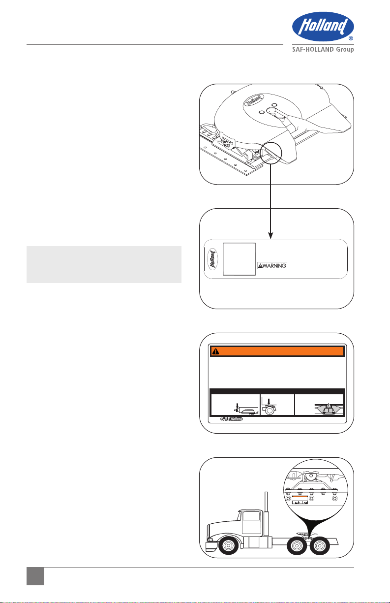
Section 3 – Decal Requirements ................3
Section 4 – Fifth Wheel Intended Use ........4
Section 5 – Fifth Wheel Non-Intended Use...4
Section 6 – Coupling Preparation ..............4
Section 7 – Coupling Procedures ...............7
Section 8 – Uncoupling Procedures .........10
Section 9 – Positioning Sliding
Fifth Wheels..........................12
Section 10 – Fifth Wheel Maintenance ....15
Contents Page
Section 11 – Top Plate Removal ..............15
Section 12 – Lube Plate Inspection.......... 16
Section 13 – Fifth Wheel Lubrication .......16
Section 14 – Slide Base Lubrication..........18
Section 15 – Fifth Wheel Adjustment .......19
Section 16 – Slide Base Adjustment
(Traditional Sliders Only) .....21
Section 17 – Upshock Cushions, Pocket
Inserts and Brackets
Inspection...........................22
Section 18 – Top Plate Installation ..........22
Section 19 – Troubleshooting ..................23
Section 20 –
Rebuild and Replacement Kits
.. 25
NOTE: Includes additional information
to enable accurate and easy
performance of procedures.
IMPORTANT: Includes additional
information that, if
not followed, could
lead to hindered
product performance.
Used without the safety
alert symbol, indicates
a potentially hazardous
situation which, if not
avoided, could result in
property damage.
Indicates a potentially
hazardous situation
which, if not avoided,
could result in minor or
moderate injury.
Indicates a potentially
hazardous situation which,
if not avoided, could result
in death or serious injury.
Introduction
This manual provides the information
necessary for the proper operation and
maintenance of HOLLAND®FW31/XA-311
(NoLube) and FW33/XA-331 (Low Lube)
Series Fifth Wheels.
Read this manual before using or servicing this
product and keep it in a safe location for future
reference. Updates to this manual, which are
published as necessary, are available on the
internet at www.safholland.us.
When replacement parts are necessary,
SAF-HOLLAND®requires the use of ONLY
SAF-HOLLAND Original Parts. A list of
technical support locations that supply
SAF-HOLLAND Original Parts and an
Aftermarket Parts Catalog are available
on the internet at www.safholland.us or
contact Customer Service at 888-396-6501.
Notes, Cautions, and Warnings
Before starting work on any SAF-HOLLAND
fifth wheel assembly, read and understand
all the safety procedures presented in this
manual. This manual contains the terms
“NOTE,” “IMPORTANT,” “CAUTION,” and
“WARNING” followed by important product
information. These terms are defined as
follows:

3
XL-FW10028UM-en-US Rev B · 2021-08-04 · Amendments and Errors Reserved · © SAF-HOLLAND, Inc., SAF-HOLLAND, HOLLAND, SAF,
and logos are trademarks of SAF-HOLLAND S.A., SAF-HOLLAND GmbH, and SAF-HOLLAND, Inc.
General Safety Instructions
IMPORTANT: These instructions apply
to the proper operation of
FW31/XA-311 (NoLube)
and FW33/XA-331 (Low
Lube) Series Fifth Wheel
top plates ONLY. There
are other important
checks, inspections, and
procedures not listed
here that are necessary,
prudent, and/or required
by law.
For proper installation procedures, refer to
Installation Manual XL-FW10008BM-en-US
available on the internet at www.safholland.us.
Failure to follow all the
operating procedures
contained in these
instructions could result
in a hazardous condition
or cause a hazardous
condition to develop
which, if not avoided,
could result in death or
serious injury.
1. General Safety Instructions
Read and observe all Warning and Caution
hazard alert messages. The alerts provide
information that can help prevent serious
personal injury, damage to components,
or both.
Failure to follow the
instructions and safety
precautions in this manual
could result in improper
servicing or operation
leading to component
failure which, if not avoided,
could result in death or
serious injury.
All fifth wheel installation and maintenance
MUST be performed by a properly trained
technician using proper/special tools,
and safety procedures.
NOTE: In the United States, workshop
safety requirements are
defined by federal and/or state
Occupational Safety and Health
Act (OSHA). Equivalent laws
could exist in other countries.
This manual is written based
on the assumption that OSHA
or other applicable employee
safety regulations are followed
by the location where work
is performed.
IMPORTANT: Prior to operation of
the fifth wheel, verify
that the fifth wheel has
been properly installed
on the vehicle.
Failure to properly install
the fifth wheel could result
in tractor-trailer separation
which, if not avoided,
could result in death or
serious injury.

4XL-FW10028UM-en-US Rev B · 2021-08-04 · Amendments and Errors Reserved · © SAF-HOLLAND, Inc., SAF-HOLLAND, HOLLAND, SAF,
and logos are trademarks of SAF-HOLLAND S.A., SAF-HOLLAND GmbH, and SAF-HOLLAND, Inc.
Model Identification
MADE IN XXXXX
SCAN QR CODE FOR PRODUCT INFORMATION
Model No. XXXXXXXXXXXXXXX
Serial No. XXXXXXXXXXXXXXX
U.S. AND FOREIGN PATENTS APPLY Ph: (888) 396-6501 or 52.1.55.5456.8641
CONSULT PRODUCT INFORMATION AT
LITKITS.SAFHOLLAND.COM PRIOR TO USING
THIS PRODUCT. FAILURE TO PROPERLY INSTALL,
MAINTAIN & OPERATE THIS PRODUCT COULD RESULT IN TRACTOR
TRAILER SEPARATION CAUSING SERIOUS INJURY OR DEATH.
QR
CODE
2. Model Identification
The fifth wheel serial tag is located on the
handle side of the fifth wheel top plate near
the pickup ramps (Figure 1).
The fifth wheel model number and serial
number are listed on the tag (Figure 2).
3. Decal Requirements
Decal XL-FW350 (Figure 3) enclosed in
the plastic bag with the Owner’s Manual,
MUST be installed near the fifth wheel and
easily viewed by the operator. Place the
decal on a flat surface such as the frame
rail or on the back of the cab (Figure 4).
NOTE: Ensure that the surface is clean
(free of oil and grease) before
applying the decal.
It is the responsibility of the end user to
periodically inspect the decal and ensure
that it is clean and completely legible. If
the label is missing, loose, damaged or
difficult to read, contact SAF-HOLLAND
Customer Service at 888-396-6501 to
order replacements immediately.
Figure 4
2.Nogap
Sinseparación
Pasd’espacement
WARNING/ ADVERTENCIA / AVERTISSEMENT
ALWAYSinspectfifth wheel
aftercouplingtractor to trailer.
Failuretoproperly couple the
tractorandtrailer could result in
tractor-trailerseparationwhile in
usewhich,if not avoided, could
resultindeath or serious injury.
CORRECTCOUPLING / ACOPLAMIENTO CORRECTO / ACCOUPLEMENT CORRECT
1.Nutandwasher snug against fifth wheel.
Tuercayarandelaajustadas contra la
quintarueda.
Écrouetrondelle
serréscontre
lasellette.
3.Lockscompletelyclosed around kingpin.
Seguroscompletamentecerradosalrededor
delpernorey.
Mâchoires
complètement
ferméessur
lepivot.
SIEMPREinspeccionela quinta
ruedadespuésde acoplar el
tractocamiónalremolque.
Sinoacopla adecuadamente el
tractocamiónyelremolque, podría
ocasionarlaseparación del
tractocamiónyelremolque durante
eluso,locual, si no se evita, podría
causarmuerteso lesiones graves.
TOUJOURScontrôlerla sellette
d’attelageaprèsavoir accouplé
letracteurà la remorque.
Unmauvaisaccouplement de la
remorquesurletracteur peut résulter
enuneséparationdu tracteur et de la
remorquesusceptiblede provoquer
lamortou des blessures graves.
Copyright©2012•SAF-HOLLAND, Inc.
www.safholland.us
Figure 3
2. No gap
Sin separación
Pas d’espacement
WARNING / ADVERTENCIA / AVERTISSEMENT
ALWAYS inspect fifth wheel
after coupling tractor to trailer.
Failure to properly couple the
tractor and trailer could result in
tractor-trailer separation while in
use which, if not avoided, could
result in death or serious injury.
CORRECT COUPLING / ACOPLAMIENTO CORRECTO / ACCOUPLEMENT CORRECT
1. Nut and washer snug against fifth wheel.
Tuerca y arandela ajustadas contra la
quinta rueda.
Écrou et rondelle
serrés contre
la sellette.
3. Locks completely closed around kingpin.
Seguros completamente cerrados alrededor
del perno rey.
Mâchoires
complètement
fermées sur
le pivot.
SIEMPRE inspeccione la quinta
rueda después de acoplar el
tractocamión al remolque.
Si no acopla adecuadamente el
tractocamión y el remolque, podría
ocasionar la separación del
tractocamión y el remolque durante
el uso, lo cual, si no se evita, podría
causar muertes o lesiones graves.
TOUJOURS contrôler la sellette
d’attelage après avoir accouplé
le tracteur à la remorque.
Un mauvais accouplement de la
remorque sur le tracteur peut résulter
en une séparation du tracteur et de la
remorque susceptible de provoquer
la mort ou des blessures graves.
Copyright © 2012 • SAF-HOLLAND, Inc.
www.safholland.us
Figure 1
Figure 2

5
XL-FW10028UM-en-US Rev B · 2021-08-04 · Amendments and Errors Reserved · © SAF-HOLLAND, Inc., SAF-HOLLAND, HOLLAND, SAF,
and logos are trademarks of SAF-HOLLAND S.A., SAF-HOLLAND GmbH, and SAF-HOLLAND, Inc.
Operation Instructions
4. Fifth Wheel Intended Use
1. Pulling trailers with 2-inch diameter
SAE-compliant kingpins which are in
good condition and securely mounted
to the trailer.
2. Transporting loads that are within the
maximum fifth wheel rated capacities:
55,000 lbs. Maximum Vertical Load
on Fifth Wheel
Standard Duty - Less than
95,000 lbs Gross Combination
Weight (GCW)
Moderate Duty (FW33 only) - Less
than 115,000 lbs Gross Combination
Weight (GCW)
3. In on-road applications.
IMPORTANT: SAF-HOLLAND
definition of off-road
refers to terrain on
which a tractor-trailer
operates which is
unpaved and rough, or
ungraded. Any terrain
NOT considered part
of the public highway
system falls under this
heading.
4. Approved applications:
Van Trailers
Tanker & Dry Bulk Trailers*
Flatbed, Stretch & Pole Trailers
End Dump (Framed) Trailers -
FW33 only
End Dump (Frameless) Trailers† -
FW33 only
Bottom Dump Trailers* - FW33 only
Lowboy Trailers* - FW33 only
B-Trains (Van, Flatbed & Stretch
Trailers)*
B-Trains (Tank & Bottom Dump
Trailers)**
B-Trains (End Dump Trailers) -
FW33 only
Converter Dollies*
*Kompensator fifth wheel mounting system available
for FW33 only.
**For Standard Duty applications, Kompensator fifth
wheel mounting system is available for FW33 only.
For Moderate Duty applications, Kompensator
fifth wheel mounting system is required. (FW31
fifth wheels cannot be used for Moderate Duty
applications.)
†No-Tilt fifth wheel mounting system required.
For additional details on the approved
applications and mounting systems
specified above, refer to the SAF-HOLLAND
Fifth Wheel Catalog & Specification Guide
(Document No. XL-FW10066SG-en-US),
available on the internet at
www.safholland.us.

6XL-FW10028UM-en-US Rev B · 2021-08-04 · Amendments and Errors Reserved · © SAF-HOLLAND, Inc., SAF-HOLLAND, HOLLAND, SAF,
and logos are trademarks of SAF-HOLLAND S.A., SAF-HOLLAND GmbH, and SAF-HOLLAND, Inc.
Operation Instructions
5. Fifth Wheel
Non-Intended Use
1. Operating with a non-SAE compliant
kingpin, such as kingpins which are bent,
have improper size or dimensions, are
not properly secured, or are installed on
warped trailer bolster plates.
Failure to couple with a
SAE compliant kingpin
could result in improper
coupling, allowing
tractor-trailer
separation, which, if not
avoided, could result in
death or serious injury.
2. Operating with upper coupler and
fifth wheel lube plates that do not
maintain the SAE kingpin dimensions.
Refer to SAF-HOLLAND Service Bulletin
(Document No. XL-SB004-01), available
on the internet at www.safholland.us,
for more information on fifth wheel
lube plates.
Failure to couple with a
SAE compliant kingpin
could result in improper
coupling, allowing
tractor-trailer separation,
which, if not avoided,
could result in death or
serious injury.
3. Tow-away operations which damage or
interfere with the proper operation of
the fifth wheel.
4. The attachment of lifting devices.
5. The transport of loads in excess of
rated capacity.
6. In off-road applications.
7. Applications other than those
recommended in the SAF-HOLLAND Fifth
Wheel Catalog & Specification Guide
(Document No. XL-FW10066SG-en-US),
available on the internet at
www.safholland.us.
Use of fifth wheel in
non-intended
applications could result
in tractor-trailer
separation which, if not
avoided, could result in
death or serious injury.
6. Coupling Preparation
1. Prior to coupling, an inspection MUST
be performed on the fifth wheel and
mounting to verify the following:
Confirm that lube plates are in
place and firmly fastened.
Tighten loose fasteners.
Replace missing fasteners.
Repair/replace missing, cracked or
otherwise damaged components.
FW33 - Inspect the fifth wheel
mechanism. Lubricate dry or rusty
components.
For a sliding fifth wheel, ensure that
both plungers are fully engaged.
Inspect air line connections.
Ensure that the fifth wheel is
properly positioned on the tractor
to accommodate appropriate axle
weight distribution. For proper
positioning of the fifth wheel, refer
to SAF-HOLLAND publication
XL-FW10008BM-en-US available on
the internet at www.safholland.us.
2. Ensure that the coupling area is flat,
level, and clear of persons and obstacles.

7
XL-FW10028UM-en-US Rev B · 2021-08-04 · Amendments and Errors Reserved · © SAF-HOLLAND, Inc., SAF-HOLLAND, HOLLAND, SAF,
and logos are trademarks of SAF-HOLLAND S.A., SAF-HOLLAND GmbH, and SAF-HOLLAND, Inc.
Operation Instructions
Figure 8
Figure 6
Figure 53. Tilt the ramps of the fifth wheel
downward (Figure 5).
4. Ensure that the locks are open.
If the locks are closed:
a. Manual Release: If equipped with
a manual secondary lock, first pull
the secondary release handle and hook
on the top plate casting (Figure 6).
Pull the release handle completely
out (Figure 7).
b. Air Release: Set the tractor parking
brake and pull the fifth wheel release
valve until the locking mechanism
opens and locks in place. Release
the pull valve. Release the tractor
parking brake.
5. Visually inspect the fifth wheel throat
to ensure that the locks are completely
open and ready to accept the kingpin
(Figure 7).
6. If the locks are NOT completely open
(Figure 7), check the following:
a. Nut and washer at the front of the
fifth wheel are NOT snug against
the fifth wheel.
b. Release handle is in the extended
“open” position.
If both of these conditions exist, you will
still be able to couple the fifth wheel
even though the lock jaws appear
closed.The movement of the kingpin
into the fifth wheel lock jaws will allow
them to open and successfully couple.
If either of the above conditions DO
NOT exist, repeat Steps 4-6.
7. Inspect the leading edge of the trailer
bolster/skid plate. It MUST be free of
any square or sharp edges (Figure 8).
TILT DOWNWARD
Figure 8
Figure 6
Figure 5
CHAMFERED (PREFERRED)
OR LARGE RADIUSED
LEADING EDGE
2" MIN
20°
Figure 7
LOCKS ARE
OPEN LOCKS ARE
CLOSED

8XL-FW10028UM-en-US Rev B · 2021-08-04 · Amendments and Errors Reserved · © SAF-HOLLAND, Inc., SAF-HOLLAND, HOLLAND, SAF,
and logos are trademarks of SAF-HOLLAND S.A., SAF-HOLLAND GmbH, and SAF-HOLLAND, Inc.
Figure 10
Figure 98. Ensure that there are no bolts or nuts
extending below the bolster/skid
plate within 6.0" (152 mm) of the
fifth wheel travel path while coupling
(Figure 9).
9. The area supported by the fifth wheel
should be free of any large holes or
gouges (Figure 9).
10. Any access holes that the fifth
wheel passes beneath should have
chamfered or radiused edges.
11. Check that any splits from the skid
plate to the bolster plate are welded
adequately, and that there are no
sharp edges or abrupt changes in
elevation (Figure 10).
12. The upper coupler should extend
adequately rearward to maintain full
contact with the fifth wheel during
tight turning. If it DOES NOT, at a
minimum, the rear edges should be
chamfered or radiused edges.
13. Ensure that any upper coupler residual
grease is free of heavy course grit.
14. Ensure that the upper coupler fifth
wheel contact surface is free of rust
and is NOT painted. The area should be
conditioned with a rust inhibitor such
as a light oil.
15. Verify that the kingpin is NOT obstructed
by a kingpin lock or other security device.
Failure to remove the
kingpin lock prior to
coupling may result in
improper coupling which,
if not avoided, could result
in death or serious injury.
16. Inspect the kingpin for excessive wear
and damage (using HOLLAND Kingpin
Gage tool TF-0110) and inspect for
any bowing of the bolster plate.
(Refer to SAF-HOLLAND Service
Bulletins XL-SB020 and XL-SB033.)
Operation Instructions
40" MIN
6" MIN
6" MIN
KEEP BOLTS AND NUTS
CLEAR OF THIS AREA
KEEP PATH OF FIFTH WHEEL FREE
OF LARGE HOLES AND GOUGES
NO ABRUPT TRANSITIONS
IN ELEVATION
MAKE SURE THERE ARE
NO SHARP EDGES
ACCESS
HOLE

9
XL-FW10028UM-en-US Rev B · 2021-08-04 · Amendments and Errors Reserved · © SAF-HOLLAND, Inc., SAF-HOLLAND, HOLLAND, SAF,
and logos are trademarks of SAF-HOLLAND S.A., SAF-HOLLAND GmbH, and SAF-HOLLAND, Inc.
Operation Instructions
Figure 12
7. Coupling Procedures
IMPORTANT: Following proper coupling
procedures for FW31
(NoLube) and FW33 (Low
Lube) fifth wheels is
extremely important.
Failure to follow all
of the procedures
contained in these
coupling instructions
may result in damage to
the lube plates.
1. Chock the trailer wheels.
2. Position the tractor so the center of the
fifth wheel is aligned with the kingpin.
3. Traveling in a straight line, slowly
back the tractor to the trailer. STOP the
tractor before making contact with the
trailer (Figure 11).
IMPORTANT: DO NOT make contact
between the fifth wheel
and trailer or damage to
the lube plates may occur.
4. Place the tractor into neutral and set
the parking brake.
5. Completely exhaust the air from the
tractor suspension, ensuring that
the fifth wheel is below the contact
surface of the trailer (Figure 12).
6. Exit the cab and ensure that the fifth
wheel is below the upper coupler plate.
Verify proper fifth wheel height. If the
trailer is too low, use the landing gear
to raise the trailer height.
NOTE: For proper operation of landing
gear, follow the instructions
published by the landing
gear manufacturer.
EXHAUST SUSPENSION AIR
BEFORE BACKING UP
Figure 11
TRAILER
(TOP)
KINGPIN

10 XL-FW10028UM-en-US Rev B · 2021-08-04 · Amendments and Errors Reserved · © SAF-HOLLAND, Inc., SAF-HOLLAND, HOLLAND, SAF,
and logos are trademarks of SAF-HOLLAND S.A., SAF-HOLLAND GmbH, and SAF-HOLLAND, Inc.
7. Slowly back up, using the lowest gear
possible. Stop when the fifth wheel is
under the leading edge of the trailer
(Figure 13).
8. Place the tractor into neutral and set the
parking brake. Exit the cab and verify
proper fifth wheel-to-kingpin alignment.
9. Adjust the tractor suspension to ride
height. The fifth wheel top plate face
MUST make contact with the upper
coupler plate (Figure 14). If the fifth
wheel DOES NOT make contact with
the upper coupler plate, use the landing
gear to lower the trailer until the fifth
wheel makes contact.
IMPORTANT: If the trailer is too high,
the kingpin will NOT
properly connect with
the lock jaws.
Failure to couple with the
trailer at the proper height
could result in improper
coupling, allowing tractor-
trailer separation which, if
not avoided, could result
in death or serious injury.
IMPORTANT: NEVER inflate the tractor
suspension when the
kingpin is above the
throat of the fifth wheel.
Failure to avoid inflating
the tractor suspension
when the fifth wheel
is NOT forward of the
king pin, could result in
damage to the kingpin and
fifth wheel.
10. Slowly back into the trailer, engaging
the kingpin into the fifth wheel.
11. Connect the air and electrical lines.
12. Raise the landing gear legs until the
pads are just above the ground.
Figure 13
BACK UP
AND STOP!
BACK UP
AND STOP!
BACK UP
AND STOP!
Operation Instructions
Figure 14

11
XL-FW10028UM-en-US Rev B · 2021-08-04 · Amendments and Errors Reserved · © SAF-HOLLAND, Inc., SAF-HOLLAND, HOLLAND, SAF,
and logos are trademarks of SAF-HOLLAND S.A., SAF-HOLLAND GmbH, and SAF-HOLLAND, Inc.
Operation Instructions
13. Perform a pull test as an INITIAL CHECK
by locking the trailer brakes and pulling
forward with the tractor to ensure that
tractor-trailer separation DOES NOT
occur (Figure 15).
14. Place the tractor into neutral and set
the parking brake.
15. Exit the cab and visually inspect for
the following to ensure that the lock
is closed:
a. Nut and washer MUST be snug
against the fifth wheel (Figure 16).
b. No gap is permissible between the
trailer upper coupler plate and the
fifth wheel (Figure 17).
c. Fifth wheel locks MUST be closed
around the trailer kingpin with 1/4"
(6.35 mm) or less gap visible between
the lock jaws (Figure 18).
16. If proper coupling has NOT been
achieved, repeat the coupling procedure.
Failure to properly couple
the tractor and trailer could
result in tractor-trailer
separation while in use
which, if not avoided,
could result in death or
serious injury.
IMPORTANT: DO NOT use any fifth
wheel that fails to
operate properly.
Failure to repair a
malfunctioning fifth
wheel before use could
result in tractor-trailer
separation which, if not
avoided, could result in
death or serious injury.
Figure 15
LOCK TRAILER BRAKES AND
PULL FORWARD WITH TRACTOR
Figure 16
Figure 17
Figure 18
NUT AND WASHER SNUG
AGAINST FIFTH WHEEL
NO GAP!
LOCKS COMPLETELY CLOSED
AROUND KINGPIN
1/4"(6.35 mm) OR LESS GAP

12 XL-FW10028UM-en-US Rev B · 2021-08-04 · Amendments and Errors Reserved · © SAF-HOLLAND, Inc., SAF-HOLLAND, HOLLAND, SAF,
and logos are trademarks of SAF-HOLLAND S.A., SAF-HOLLAND GmbH, and SAF-HOLLAND, Inc.
17. Fully retract the landing gear legs
off the ground and secure the crank
handle (Figure 19).
NOTE: For proper operation of landing
gear, follow the instructions
published by the landing
gear manufacturer.
18. Remove the wheel chocks and continue
with the pre-trip inspection.
NOTE: For no-tilt fifth wheels used
with rigid upper couplers,
always remove the no-tilt shaft
assembly for on-road use.
8. Uncoupling Procedures
IMPORTANT: Following proper
uncoupling procedures
for FW31 (NoLube) and
FW33 (Low Lube) fifth
wheels is extremely
important.
Failure to follow all of
the procedures contained
in these uncoupling
instructions may result in
damage to the lube plates.
1. Position the tractor and trailer, in straight
alignment, on firm, level ground clear
of obstacles and persons.
2. Set the trailer brakes.
3. Slowly back the tractor tightly against
the trailer to relieve pressure on the
fifth wheel locks.
4. Place the tractor into neutral and set
the parking brake.
IMPORTANT: DO NOT exhaust air from
the tractor suspension
before uncoupling.
Operation Instructions
Figure 19
SECURE
CRANK
Figure 20
LOWER LANDING GEAR
Failure to avoid
exhausting air from the
tractor suspension before
uncoupling could result in
difficulty uncoupling the
tractor from the trailer
which, if not avoided, could
result in damage to the
fifth wheel and kingpin.
5. Chock the trailer wheels.
6. Lower the landing gear until the pads
just touch the ground (Figure 20).
NOTE: For proper operation and ability
to transfer the trailer weight
from the fifth wheel, follow the
instructions published by the
landing gear manufacturer. DO
NOT raise the trailer off of the
fifth wheel.

13
XL-FW10028UM-en-US Rev B · 2021-08-04 · Amendments and Errors Reserved · © SAF-HOLLAND, Inc., SAF-HOLLAND, HOLLAND, SAF,
and logos are trademarks of SAF-HOLLAND S.A., SAF-HOLLAND GmbH, and SAF-HOLLAND, Inc.
Operation Instructions
7. Disconnect the air and electrical lines
from the trailer and secure to the tractor.
8. If equipped, pull the secondary lock
release handle and hook on the top
plate casting (Figure 21).
9. Pull the release handle (Figure 22).
If air release is equipped, pull and hold
the fifth wheel release valve until the
locking mechanism opens and locks
into place.
10. Ensure that the locking mechanism is
open and the yoke shaft is in the out
position (Figure 23).
11. Release the tractor parking brake and
slowly pull forward 12"-18" (306-457 mm)
to disengage the kingpin from the
fifth wheel. The fifth wheel should be
between the front edge of the trailer
and the kingpin (Figure 24).
IMPORTANT: DO NOT drive the tractor
free of the trailer.
SLOWLY PULL FORWARD
AND STOP
Figure 24
Figure 21
Figure 22
Figure 23
YOKE SHAFT IN OUT POSITION

14 XL-FW10028UM-en-US Rev B · 2021-08-04 · Amendments and Errors Reserved · © SAF-HOLLAND, Inc., SAF-HOLLAND, HOLLAND, SAF,
and logos are trademarks of SAF-HOLLAND S.A., SAF-HOLLAND GmbH, and SAF-HOLLAND, Inc.
12. Place the tractor into neutral and set the
parking brake. Completely exhaust the
air from the tractor suspension, ensuring
that the fifth wheel is below the contact
surface of the trailer (Figure 25).
13. Visually inspect uncoupling. Ensure
that the trailer is completely supported
by the landing gear.
14. Release the tractor parking brake and
slowly pull away from the trailer.
15. Apply air to the tractor air suspension
and allow the suspension to return to
ride height (Figure 26).
9. Positioning Sliding
Fifth Wheels
NEVER reposition a sliding
fifth wheel while the
tractor-trailer is in motion
or on public roads. Failure
to avoid could cause loss of
vehicle control or tractor-
trailer separation which, if
not avoided, could result in
death or serious injury.
1. Position the tractor and trailer, in straight
alignment, on firm, level ground clear
of obstacles and persons.
2. Place the tractor into neutral and set
the tractor and trailer parking brakes.
Failure to stop and properly
lock the tractor and
trailer brakes could cause
uncontrolled sliding of the
fifth wheel which, if not
avoided, could result in
component damage to the
tractor or trailer.
Operation Instructions
Figure 26
Figure 25
RETURN TRACTOR
SUSPENSION TO RIDE
HEIGHT
EXHAUST SUSPENSION
AIR BEFORE PULLING
FORWARD

15
XL-FW10028UM-en-US Rev B · 2021-08-04 · Amendments and Errors Reserved · © SAF-HOLLAND, Inc., SAF-HOLLAND, HOLLAND, SAF,
and logos are trademarks of SAF-HOLLAND S.A., SAF-HOLLAND GmbH, and SAF-HOLLAND, Inc.
Operation Instructions
3. Release the slide locking plungers by
moving the cab switch to the unlock
position (Figure 27). If equipped
with manual slide release (Traditional
Sliders only), pull the release lever. If
the plungers DO NOT come out, lower
the landing gear to relieve pressure on
the fifth wheel. This will allow the fifth
wheel to slide easier.
NOTE: Cab switch style may differ by OEM.
4. Visually inspect and verify that the
plungers are disengaged.
Figure 28 - ILS Sliders
Figure 29 - Severe-Duty Sliders
Figure 30 - Traditional Sliders
5. Release the tractor parking brake while
keeping the trailer brakes engaged.
6. Slowly drive the tractor forward or
backward to position the fifth wheel.
Stop the tractor at the desired position.
7. Re-engage the slide locking plungers
by moving the cab switch to the lock
position (Figure 31). If equipped
with manual slide release (Traditional
Sliders only), pull the release arm to
allow the plungers to retract.
Figure 27
AIR OPERATED
MOVE CAB SWITCH TO
UNLOCK POSITION
Figure 28
RACKS
PLUNGERS RETRACTED
UNLOCKED
(DISENGAGED) ILS SLIDERS
Figure 29
RACKS
PLUNGERS
RETRACTED
LOCK INDICATORS
POINT TO UNLOCK
SYMBOLS WHEN
DISENGAGED
Figure 30
UNLOCKED
(DISENGAGED)
UNLOCKED
(DISENGAGED)
TRADITIONAL SLIDERS
(DISCONTINUED)
SEVERE-DUTY
SLIDERS
PLUNGERS
EXTENDED
RACK

16 XL-FW10028UM-en-US Rev B · 2021-08-04 · Amendments and Errors Reserved · © SAF-HOLLAND, Inc., SAF-HOLLAND, HOLLAND, SAF,
and logos are trademarks of SAF-HOLLAND S.A., SAF-HOLLAND GmbH, and SAF-HOLLAND, Inc.
8. Place the tractor into neutral and set
the parking brake.
9. Visually inspect the plungers to ensure
proper engagement.
Figure 32 - ILS Sliders
Figure 33 - Traditional Sliders
Figure 34 - Severe-Duty Sliders
10. Retract the landing gear legs, if lowered.
11. Verify that the slide locking plungers
have been re-engaged by performing a
pull test (Figure 35).
IMPORTANT: DO NOT operate the
vehicle if the plungers are
NOT fully engaged (locked).
Failure to properly engage
the plungers and slide
base could cause loss of
vehicle control which, if
not avoided, could result
in death or serious injury.
Figure 35
LOCK TRAILER BRAKES AND
PULL FORWARD WITH TRACTOR
Operation Instructions
Figure 31
AIR OPERATED
MOVE CAB SWITCH
TO LOCK POSITION
Figure 32
LOCKED (ENGAGED)
RACKS
PLUNGERS
ILS SLIDERS
Figure 34
LOCK INDICATORS
POINT TO LOCK
SYMBOLS WHEN
ENGAGED
RACKS
LOCKED (ENGAGED)
SEVERE-DUTY SLIDERS
PLUNGERS
(UNDER BRACKETS)
Figure 33
LOCKED
(ENGAGED)
RACK
PLUNGER
TRADITIONAL SLIDERS (DISCONTINUED)

17
XL-FW10028UM-en-US Rev B · 2021-08-04 · Amendments and Errors Reserved · © SAF-HOLLAND, Inc., SAF-HOLLAND, HOLLAND, SAF,
and logos are trademarks of SAF-HOLLAND S.A., SAF-HOLLAND GmbH, and SAF-HOLLAND, Inc.
Maintenance Procedures
1. Remove the bracket pin retention nuts
and bolts from both sides of the fifth
wheel top plate (Figure 36).
2. Using a pry bar, pull the bracket pins out
of the fifth wheel top plate (Figure 36).
3. Using a lifting device capable of lifting
500 lbs. (227 kg), remove the top plate
from the mounting base. Place the fifth
wheel on a flat, clean working area.
NOTE: Follow the instructions
published by the lifting device
manufacturer for proper
operation of the lifting device.
10. Fifth Wheel Maintenance
IMPORTANT: All maintenance
MUST be performed
by a properly trained
technician using
proper tools and
safety procedures.
IMPORTANT: All maintenance MUST
be performed while the
tractor is uncoupled
from the trailer.
Failure to properly maintain
the fifth wheel could
result in tractor-trailer
separation which, if not
avoided, could result in
death or serious injury.
1. For steps required for fifth wheel
maintenance, refer to Step 1 of Section 6
and all steps in Sections 11 through 18.
NOTE: Removal of the fifth wheel
top plate is NOT required for
maintenance but may be required
when performing repairs.
11. Top Plate Removal
IMPORTANT: FW31 (NoLube) and
FW33 (Low Lube) fifth
wheel assemblies have
replaceable pocket
inserts installed between
the fifth wheel top plate
and mounting base.
When removing the top
plate, take care NOT
to lose the pocket inserts.
Failure to prevent pocket
inserts from falling out of
the top plate could cause
a potentially hazardous
situation which, if not
avoided, could result in
minor or moderate injury.
Figure 36
RETENTION NUT
RETENTION BOLT
TOP
PLATE
BRACKET PIN
Figure 37
LOOK FOR
STRAIGHT
EDGE
CONTACT
HERE

18 XL-FW10028UM-en-US Rev B · 2021-08-04 · Amendments and Errors Reserved · © SAF-HOLLAND, Inc., SAF-HOLLAND, HOLLAND, SAF,
and logos are trademarks of SAF-HOLLAND S.A., SAF-HOLLAND GmbH, and SAF-HOLLAND, Inc.
Maintenance Procedures
12. Lube Plate Inspection
Thoroughly steam clean the top surface
of the fifth wheel for visual inspection.
Replace the lube plates if:
One or both lube plates is missing.
A straight edge laid across the lube
plate contacts any metal portion of the
fifth wheel surrounding the lube plates
(Figure 37).
Lube plates are severely chipped, worn,
cracked, gouged or bent.
20% (40 sq. in.) or more of lube plate
coating is missing from one or both
plates due to normal wear or damage.
13. Fifth Wheel Lubrication
FW31 and FW33 Series fifth wheels
are both equipped with NoLube lube
plate inserts that eliminate the need
to lubricate the fifth wheel-to-trailer
contact surfaces.
Thoroughly clean the locking
mechanism every six (6) months or
60,000 miles.
13.1 FW31 (NoLube) Series:
FW31 Series fifth wheels are equipped
with NoLube lock coating technology.
The lock components are protected
with a low-friction coating which
provides long wear life and corrosion
protection, eliminating the need for
lubrication. The locking mechanism
of a new FW31 Series fifth wheel
assembly has a thin layer of grease
applied by SAF-HOLLAND to aid the
components for an initial “break-in”
period. Grease will not adversely affect
a FW31 Series NoLube fifth wheel.
IMPORTANT: If the FW31 Series
NoLube fifth wheel
operates in snowy or
icy winter conditions,
maintenance should be
performed every spring
to ensure optimum
operation. FW31 Series
NoLube fifth wheels that
are exposed to harsh
and dry chemicals and/
or road salt should be
steam cleaned and the
(B) cam profile, (D)
secondary lock where
contact is made with
the cam plate, and (E)
release handle should
be lubricated per
Section 13, Step 1.a.
13.2 FW33 (Low Lube) Series:
IMPORTANT: Fifth wheel lubrication
is necessary to get the
maximum service life
from the FW33 Series
fifth wheel. Perform the
following procedures at
the intervals listed.
FW33 Series fifth wheel locking
mechanisms require periodic lubrication.
Lubricate the FW33 Series fifth wheel
locking mechanism every three (3)
months or 30,000 miles.
IMPORTANT: If the FW33 Series
fifth wheel operates
in snowy or icy winter
conditions, lubrication
should be performed
every spring in addition
to routine lubrication (as
noted above) to ensure
optimum operation.

19
XL-FW10028UM-en-US Rev B · 2021-08-04 · Amendments and Errors Reserved · © SAF-HOLLAND, Inc., SAF-HOLLAND, HOLLAND, SAF,
and logos are trademarks of SAF-HOLLAND S.A., SAF-HOLLAND GmbH, and SAF-HOLLAND, Inc.
Maintenance Procedures
Figure 39
Figure 40
SUPPLY FITTING
PISTON SHAFT
Figure 38
A
B
F
D
E
C
G
Figure 41
LOCKING MECHANISM (YOKE TIPS, LOCK
PINS AND KINGPIN CONTACT AREA)
1. Proper Lubrication Method:
a. Using water-resistant lithium-based
grease, lubricate (A) the yoke tips
where contact is made with the
locks and top plate casting, (B) cam
profile, (C) yoke shaft in area that
slides in and out of the top plate
casting, (D) secondary lock where
contact is made with the cam plate,
(E) release handle, and (F) lock
jaws where contact is made with
the kingpin (Figure 38).
b. Using a light oil, lubricate the (G)
cam pivot point (Figure 38).
If equipped with air release, follow Steps “c”
through “h” for lubrication of the air cylinder.
c. Inspect the air cylinder tube and
shaft for dents, bending, or other
damage and replace as necessary.
d. Activate the air cylinder control
to extend the piston and shaft to
its full travel length (Figure 39).
e. Clean the exposed piston shaft with
penetrating oil and a clean shop
towel. DO NOT use any abrasives
on the exposed shaft as they could
damage the piston shaft.
f. De-activate the air cylinder.
g. Remove the supply air line and
add two to four (2-4) drops of air
tool oil to the cylinder through
the supply fitting. Re-install the
supply air line (Figure 40).
h. Activate and de-activate the air
cylinder two to three (2-3) times
to work the air tool oil into the
cylinder and onto the piston and
verify proper operation.
2. As-Needed Lubrication:
Clean and lubricate the locking
mechanism if operational difficulties
arise during the service life of the
fifth wheel (i.e., problems with
coupling, uncoupling, or pulling the
release handle) (Figure 41).

20
Maintenance Procedures
XL-FW10028UM-en-US Rev B · 2021-08-04 · Amendments and Errors Reserved · © SAF-HOLLAND, Inc., SAF-HOLLAND, HOLLAND, SAF,
and logos are trademarks of SAF-HOLLAND S.A., SAF-HOLLAND GmbH, and SAF-HOLLAND, Inc.
Figure 42
14. Slide Base Lubrication
NOTE: Slide base should be moved fore
and aft at least once a year to
maintain optimum performance.
IMPORTANT: If equipped with air
release, lubricate the air
cylinder every three (3)
months or 30,000 miles
whichever comes first.
ILS (Integrated Low-Weight) Sliders:
1. Spray the spring-covered piston
shaft thoroughly with penetrating oil
(Figure 42).
IMPORTANT: DO NOT use any abrasives
on the exposed shaft as
they could damage the
piston shaft.
2.
Remove the supply air line and add two to
four (2-4) drops of air tool oil to the cylinder
through the supply fitting. Re-install the
supply air line (Figure 43).
3. Activate and de-activate the air cylinder
two to three (2-3) times to work the air
tool oil into the cylinder and onto the
piston and verify proper operation.
Severe-Duty Sliders:
1. Spray the spring-covered piston
shaft thoroughly with penetrating oil
(Figure 44).
IMPORTANT: DO NOT use any abrasives
on the exposed shaft as
they could damage the
piston shaft.
2.
Remove the supply air line and add two to
four (2-4) drops of air tool oil to the cylinder
through the supply fitting. Re-install the
supply air line (Figure 45).
3. Activate and de-activate the air cylinder
two to three (2-3) times to work the air
tool oil into the cylinder and onto the
piston and verify proper operation.
PISTON
SHAFT
ILS SLIDERS
Figure 43
ILS SLIDERS
SUPPLY
FITTING
Figure 44
Figure 45
PISTON SHAFT
SUPPLY FITTING
SEVERE-DUTY
SLIDERS
SEVERE-DUTY SLIDERS
This manual suits for next models
1
Table of contents
Other SAF-HOLLAND Automobile Accessories manuals

SAF-HOLLAND
SAF-HOLLAND Holland DB-100SH1 User manual

SAF-HOLLAND
SAF-HOLLAND Yard Spotter Series User manual

SAF-HOLLAND
SAF-HOLLAND HOLLAND FW17 Series Reference manual

SAF-HOLLAND
SAF-HOLLAND DB-1400 User manual

SAF-HOLLAND
SAF-HOLLAND Holland DB-610-30 User manual

SAF-HOLLAND
SAF-HOLLAND HOLLAND DB-1249-49 User manual

SAF-HOLLAND
SAF-HOLLAND FleetMaster LowLube Series Installation guide

SAF-HOLLAND
SAF-HOLLAND DB-1250-3 User manual

SAF-HOLLAND
SAF-HOLLAND FleetMaster Air FW8 Series User manual

SAF-HOLLAND
SAF-HOLLAND Tire Pilot Plus User manual