Spencer Buffalo Model 44 Owner's manual
F
|,
li
1I
I
i
lITF]tE
NITXCROSCOPE
CONSTRUCTION, USE AND CARE
PUBLISHED BY
SPENCER LENS COMPANY
BIJFFALO, N.Y.

THE
CONSTRUCTION, USE
AND CARE
of the
MICROSCOPE
A brief outline of the mechanical and
optical principles involved, with
special referencc to efficient
manipulation
PUBLISHED BY
SPENCER LENS COMPANY
BUFFALO, N.Y.

Copyright r9z6
by Spcocer Lcns Compaoy
FOREWORD
HE importance of a thorough knowledge of the
microscope is more and more recognized as a
necessity, antecedent to courses in which the
instrument is used. Naturally the best work is done
only after an intimate understanding of the use and
relations of the different parts; and how to keep them in
perfect working condition.
We are glad to respond to the demand for a short
treatise on the construction, the care, and the use of
the instrument-both mechanical and optical-going
into detail only in so far as is necessary to make the
instrument an efficient means for the study of the
subject at hand.
Let it be remembered that no amount of direction
will take the place of good judgment and careful,
painstaking effort on your part, and that it is only
the perfect adjustment of every part in relation to
every other part which brings the best results. The
neglect of one detail may destroy the virtues of all
the oLhers.
We desire that the use of the instrument may prove
to be of great profit and great pleasure as well.
Sppwcnn Lows Coupawy
.-|-
I
I
I
f
f
o
II
t-
'o
z
Solt Tua.--1-
u
n
FT
I
I
1.1o"ro,r.rJ -
I
I
gu"r"r,rl=-L-:--
Gnr::g1ro Sxor:ff j
Revorv rx
Srnqe--
Rn.rusrqgue-3
Srnrxq rr ^iiir.
Coruor Nscr Ho'uriirfi
Lowrn lnrsDrqr-"{ifi
ron Orurque Ll{xr, nl}
Stqqe Crxrrlruq -4
HtRRoR_9!:Y:iN
Ocuuqn.
----DRqw-Tuse.
---Bq.*$Prurou
(/oqRsL \DlUSrnr4r.
-- Frl.le \otusrr.rtxt
BurroNs
- -CoNce.tnrc
\o lusr r x qB ur r ox:,
.RqDUqTLD LoN6
5r-rpe
-- Rcn
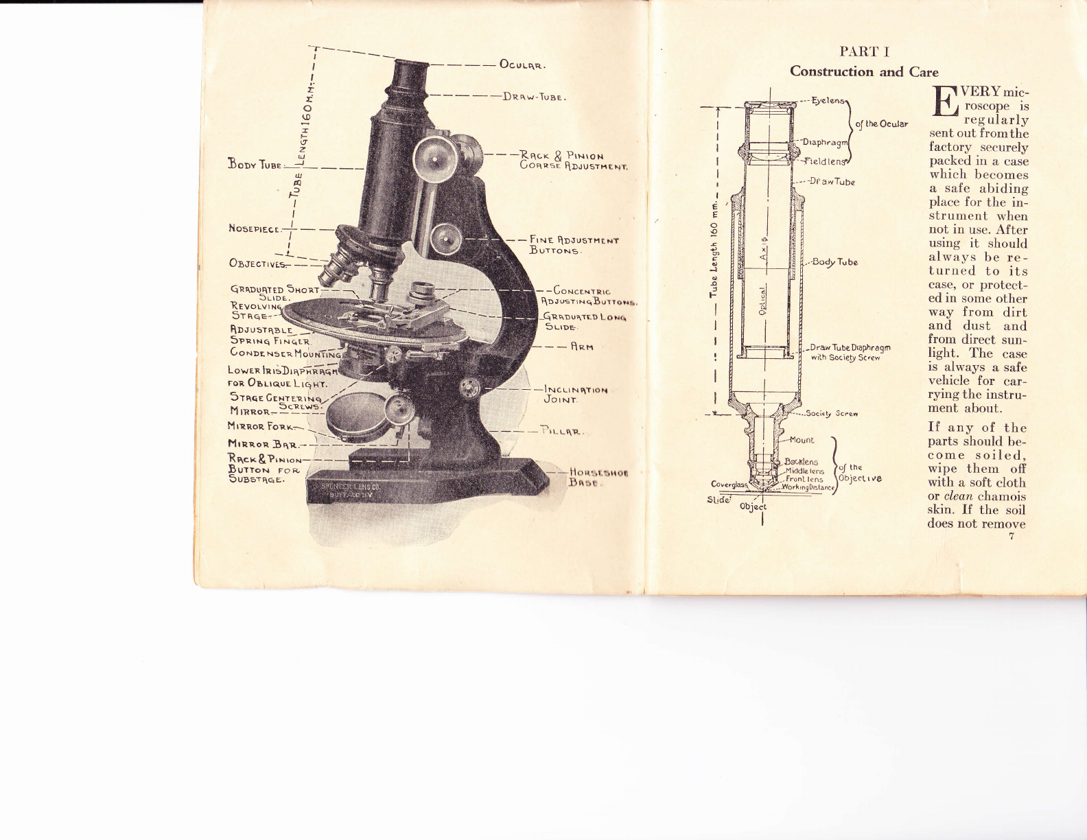
PART I
Construction and Care
ti
:--lucrrNq.rroH
Jo r rqr
lrr-rqn-
E
E
--
C
J
s
a
F
I
I
I
:
I
I
_t-_
oJ the Ocular
-- tt awTqbe
..'Bod2-lube
.-Dre Tube Draph.agn
with Socie$r Sc'€w
-Socie! 5cren
lr/roscope.rs
reg ularly
sent out fromthe
VERYmic-
factory securely
packed in a case
which becomes
a safe abiding
place for the in-
strument when
not in use. After
using it should
always be re-
turned to its
Case, or protect-
ed in some other
way from dirt
and dust and
from direct sun-
light. The case
is always a safe
vehicle for car-
rying the instru-
ment about.
If any of the
parts should be-
come soiled,
wipe them off
with a soft cloth
ot clean chamois
skin. If the soil
does not remove
l''lttnoc Fonr.- --\tffi
i'ltRr.on 3^1. ) *)-X
Rhcx&T,*ro*---
Butto..r ro p- ;
SuBsrqqg. fi * Horstsnoo
.Bnst
.--llounL
Baoxlens
.Hiddl€ lcs
-.front l(ns
objo

easily, breathc on the surface and rub gently. If this is
not successful, try moistening with a little xylol, ether
or chloroform, if indeed, water previously tried does
not accomplish the end. Dry as soon as possible. lfeaer
use alcohol on lacquered parts unless you hnow Lhe
lacquer is alcohol proof. Fortunately nearly all lac-
quers now used are not soluble in alcohol. The black
enamels which are more and more extensively used
are not affected by any of the ordinary reagents.
The modern microscope is more compact, solid and
rigidly built than those in use some years ago. It is
better adapted to the serious purpose of modein labo-
ratory methods. In all makes much careful engineer-
ing skill has been exercised to make a durable and
efficient instrument.
Base and Fillar
Beginning n'ith the base, stability is attained more
by weight than by spread of the feet. Usually the
base and pillar are one casting, althougfr on some
microscopes tlr"V g_" made separatcly and securely
fastened together. There is no advantage either way.
Inclination Joint
Practically all microscopes are provided with incli-
nation joints by which the body of the instrument
is movably fastened to the top of the pillar so that
it may be inclined to any angle which ease and con-
venie-nce- may dictate. The joint should work smoothly
and freely and yet with sufficient friction to hold thL
body at any inclination.
There are several types of construction as illustrated.
fn -all of them the pil]ar forms two parts of the hinge
while the lowcr end of the arm is made to fit betwee"n.
In all the best types the taper axle, or a modification,
I
is predominant. The necessary friction is obtained by
drawing the cole into its bearing and compressing th"e
sides of the pillar.
I
i
IItig. A l,'is. B Fis. C
Once in a long while one of these joints may.work loose
s.g_ that the body will not remain at the desired angle.
This may be remedied by tightening the nuts on lhe
ends of the axis. These nuts are usually provided with
two small holes for a " spanner wrenr.h." Usuallv
tightening the nut on the right side of the instrumenl
draws the conical axis farther into its bearing. Some-
times it is necessary previously to slightly loosen the
nut on the other side-tightening it again later.
ff a spanner is not convenient the nut'can usually be
turned_with a pair of round nosed pliers. In any in-
stance be careful not to mar the nut around the lioles.
The Body
The body of the microscope is made tp of the Arm,
which on the best instruments is of briss or bronze,
Lhe Intermediate Slide whose bearings and movement
on the arm are controlled by the Fine Adjustment,
I,'i11. BFis. C

and the Body Tube, rvhose bearings and movement
on the intermediate slide are controlled by the Coarse
Adjustment. The Fine Adjustment
The fine adjustment is the vital part of the microscope
stand. No high power work can be done without its
proper functioning. One of the essentials is a perfectly
fitting bearing which permits a free up and down move-
ment in a line at 90o from the plane of the stagc, with
no lateral motion. The metal forming these bearing
surfaces should be of such texture, the fitting so per-
fect, and the lubrication such that the movement
always responds immediately to the least impulse.
These bearings should be protected from dust and
other foreign matter, and should be lubricated with
oil which will not become gummy and sticky.
If for any reason these, or any other, bearing surfaces
should become gummed, clean them ofr with xylol
or chloroform, and re-lubricate with white vaseline.
On all Spencer micros<:opes oil grooves are put in all
bearing surfaces to hold & reserve supply of the lubri-
cant.'l'his insures a smooth movement which can not
be accomplished in any other way.
ff, when working the fine adjustment up and down,
while the eye is at the eyepiece, the object appears
to move sidewise, the light coming from the mirror
is not central, or there is a lateral movement in the
fine adjustmcnt bcarings. If upon carefully centering
the light the :rpparent movement of the object per-
sists, the trouble is in the fine adjustment-either poor
fitting, a decided lateral thrust in the mechanism pro-
ducing the movement impulse-or both. It should not
occur.
t0
The mechanism for supplying the impulse must of
ne-cessit-y_ b_e_ of extreme accuracy, delicacv and dura_
bilit)'. N.othing in mechanics *ill """o*plish this-as
well as the mrcrometer screw l,ith a sufficient number
of threads in contact with its nut; especiatty *t "" "."a
in conjunction with the lever.
There are two classes of fine adjustments: the older
with the micrometer thleads peipendicular and the
fine adju.stment head at the to| oi the arm; and the
newer with two fine adjustment heads, one on either
side of the arm. The latter is the more convenient
and is rapidly replacing the former. Of the former there
are two disl.inr.t types: the one (Figure D) where the
whole arm mov('s on a triangular pillar, and the olher
-later and better-rvhere the intermecliate slicle moves
on the arm actuated by a lever in connection with the
micrometer screw (Figure E).
tr'is. DFis. E
Stop nuts are provided at the end of the micrometer
screw to prevent the fine threads being removed from
their bearings. Sometimes these nuts are forced off,
and the micrometer threads are removed. When this
occurs be careful in replacing these very fine threads
to see that they are started straight, and that they
do not " run." Do not force the threads if they go at
all hard. It will help to know that on most microscopes
these threads are left handed. Care should also be
taken to see that the little pin P, which fits loosely
into the hollow end of the micrometer screw, is in
position. Should it be lost it must be replaced. Should
it fall into the mechanism it can be secured only by
removing the nut N at the top of the arm. In some
instances the pin drops out before the micrometer
thread is entirely out of its trearings, and the defect
is not noticed until the fine adjustment does not re-
spond. As stated above remove the large nut at the
top of the arm to replace the pin.
Most of the modeln microscopes are of the second
class where the trvo firre adjustmcnt heads are one on
either side of the arm. 'I'he mechanism here is slightly
more complicated, hence the need for the best mechani-
cal principles.
The bearings for the shaft connecting the two heads
are on cither sidc of the arm and should be in precise
alignment for the free turning of the shaft. In no way
is this accomplished as well as where the two bearings
are in one continuous piece passing through the arm.
Here as in the other class the micrometer in conjunc-
tion with the lever stands out as superior. Here there
are a goodly number of threads always fully engaged
through 360" of each thread, insuring a steady, regular
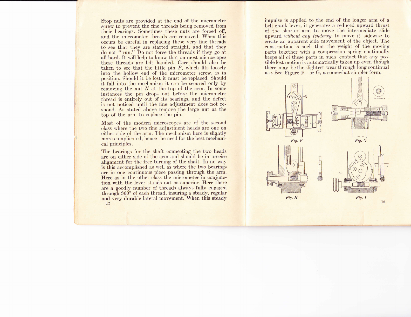
and very durable lateral movement. When this steady
t2
impulse is applied to the end of the longer arm of a
bell crank lever, it generates a reduced upward thrust
of the shorter arm to move the intermediate slide
uprvard without any tendency to move it sidervise to
create an apparent side movement of the object. The
construction is such that the weight of the moving
parts together with a compression spring continually
keeps all of these parts in such contact that any pos-
sible lost motion is automatically taken up even though
there may be the slightest wear through long continual
use. See Figure F-or G, a somewhat simpler form.
B
A
Fis. FFig. G
Fis. HFig. I

Figure H represents a fine adjustment enscmble quite
similar to that of Figure G except that the micrometer
thread is replaced by a worm-gear device. A segment
of a gear takes the place of the nut and the long arm
of the bell crank lever. The impulse from the short
arm is upward, producing no lateral thrust as is also the
case in Figures F and G. On all of the above described
adjustments provision is made for automatically stop-
ping the revolution of the shaft when the adjustment
has reached the limit of its excursion, thus avoiding
any injury to the threads or gears.
Figure I represents another worm-gear fine adjustment
in which the complete gear circle is used. On this gear
is fastened an eccentric heart shaped cam on the peri-
phery of which a small roller is made to revolve. This
roller is attached to the movable parts of the fine
adjustment. When the gear levolves in the direction
of the arrow as shown in the cut, one of the components
of the movement of the heart shaped cam forces the
roller upward, and will continuc to do so uritil the apex
of the heart passcs undcr thc roller whcn it will then
move downward for 180" of the revolution. It has the
advantage thaL the fine adjustmcnt never "runs out."
An entircly ncw fine atljustment (see Figure J) has
recently come out.in which_ the necessary reduction
,FB is attained by means of a chain of
splrr gears similar to clock gears
working in conjunction with a lever.
It is very different from the types
just described. It provides the
dircct upward thrust. The fine ad-
justment head is represented at F.B.
All standard microscopes are now
made so that the positive impulse is always upward
l4
against a slightly compressed spring. The mechanism
allows the movable parts to descend by gravity and
the force of the compression spring. Therefore in focus-
sing down one is not so apt to cause damage if the
front of the objective should come into contact with
the cover glass. Avoid this contact if possible. If at all
uncertain observe the proximity of the objective to
the cover glass before looking into the eyepiece.
ff when looking into the eyepiece no change of focus
is noticed by turning the fine adjustment, it is quite
possible that the objective is resting on the cover glass.
It is possible that the fine adjustment may have " run
out." It is always bcst to kecp the finc adjustment
about midr,vay in its range. If the microscope is one
provided with positivc stops :rt the ends of its cxcursion,
it will be necessary to place the rnechanism sornewhere,
near the midway point. If the microscope is one with
the fine adjustment head at the top of the arm, the
loose pin in the end of the micrometer screw may have
been misplaced. See page 12.
The Coarse Adjustment
The Coarse Adjustment or rapid movement of the body
tube is now affected on all microscopes by means of
the diagonal rack and pinion. The bearing surfaces on
the American and lluropean instruments are quite dif-
ferent. Both are good. 'Ihere is no advantage either
way except for the oil grooves on Spencer microscopes.
The bearings are very closely fitted. Any foreign matter
on the surfaces scriously interferes.
Do not strain the teeth of the rack and pinion by forcing
the bearings llack and forth over one another when they
are not clean. A little xylol or chloroform rubbed on
the surface will clean them. Do not use emery o. ?;r"
Fis. J

other abrasive. When the bearings are perfectly clean,
oil them slightly with a good acid free lubricant (par-
affin oil or watch oil). If the bearings become so loose
that the tube will not stay in placc, tighten the little
screws at the back of the pinion box. All makers have
a provision here for taking up lost motion and wear.
Do not fill the teeth of the rack with. paper, paraffin
or any other foreign substance. If anything should
accumulate in these teeth, clean them out.
The Body Tube
The body tube, together with the draw tube, is the
support for the principal optics of the microscope' Thg
obiectives are located at the lower end of the tube and
the eyepieces at the upper end. The graduated tele-
scoping-draw tube provides a means for varying the
length of the tube (See page ? ) . It should move smooth-
ly and easily. In pushing it in be careful not to push
down the whole body tube to injure the.specimen or
the objective by bringing the objective violently into
contact with the cover glass.
Binocular Body Tube
A comparatively new bod.y tube has been introduced
bv whiih both eyes may be used while working with
a- single obicctive. 'I'hesc binocular body tubes are
interchangeable with the single tube without disturbing
the objecfives. 'lhis is particularly true of the Spenc-er
device- by which either body when loosened may be
lifted oui of place and the other replaced without the
least danger of disturbing the focus of the highest power
objectives.
Asillustratedonnextpage the light from the objective
is divided by two cemented prisms immediately above
16
tr'is. K
the objective. The 45o
surface of one of these
prisms is semi-platinized
to reflect half the light
to one side, and allow
the other half to pass
through to be reflected
in the opposite direction
by another 45o reflecting
surface. These tlvo beams
of light are again reflect-
ed upward, each to its
eyepiece, by prisms lo-
cated directly belorv the
eyepieces and rnoving
rvith thern. 'I'he eyepieces
arc rnovablc to and from
one another to accom-
modate different inter-
pupillary distances. One of the eyepiece tubes is
also variable as to length to adjust for a difierence
between the two eyes of the same person.
There are two distinct types of these binocular bodies:
the one with the parallel eyepiece tubes and the other
with the tubes slightly converging toward the objective.
The argument for the parallel tubes seems to be that
they are more rcstful for the eyes because " the eyes
are at rcst rvhcn looking at an object at infinite dis-
tance."Over against this is tlie stubborn fact that when
using thc parn.llcl tubes many people have difficulty
blending thc two imagcs into one picture as is regularly
done in ordinary vision. Quite a number are able to
do it after some practise. Some never accomplish it'
In looking into the converging tubes there is no sttch
trouble. Normally when looking at a near objcct the

l!1es o! light converge from the eyes to the object.
When looking at a microscope, or observing the plac-
!ry of a slide on the stage, the eyes are converging.
No adjustment is necessary when immediately Iooking
into Lhe microscope. The images appear as one. Again
no readjustment is necessary in looking away from the
microscope image to pick up a pencil to make notes.
The binocular body is a great advantage because
it permits the use of both eyes, greatly relieving the
strain on one eye when using the single tube, especially
for long continuous observation. At the same time it
presents a picture of the object not obtainable with
the single tube. Some claim that the vision is stereo-
scopic; others assert that it is not truly stereoscopic.
Be that as it may, all agree that the view is much mbre
satisfactory, and more restful to the eyes for long con-
tinued work. Without doubt different layers in the
structure of the object are much more easily differ-
entiated.
The disadvantage of using the two eyepieces is
the fact that the divirle<l lig'ht will not present so
brilliant a field with thc sarne light source. Many,
therefore, considcr thc singlc eyepiece better when a
brighter field is dcrnaudcd and when the exigencies
require the most cirilical definition and resolution.
Without doulrt thc two views of the same object are
different antl both rnake for a more intelligent inter-
pretation. 'l'lren'fort., rnosl workers are willing to use
both tubes cverr though the interchange is more or
less cumbersomc.
Combination Body Tube
To overcome this the Spencer Lens Company has
recently designed a combination body tube providing
l8
a quick and easy interchangeability between the single
and double eyepieces. For the binocular vision both
eyepieces are used in the usual way. lVhere the single
eyepiece is desired the body is moved slightly to one
side to bring the axis of one eyepiece coincident with
that of the objective, duplicating the conditions of the
single tube. All of the prisms and the other eyepiece
are automatically moved out of the way. The con-
.i
I,'iu. L
i
Fis.M
venience of tlrrr rkrvice imrnediately appeals to th<:
research workcr. lligrrrc L shorvs the position of thc
parts when botlr cycpic(:es {rre used. Figure M shorvs
the'same parts in tlrc lrosition assumed when buL ont:
eyepiece is in worliirrg position.
The Nosepiece
The body tubes of practically all microscopes are now
so made that the nosepiece is a necessary concomitant
to provide the proper tube length and to permit the
objective being brought closs enough to the stage.
The convenience of the quick interchange of objectives
has become a necessity. The objectives sent out vrith
all microscopes are made par.fctcal on the nosepiece:
i. e., they are of such length that when one is in focus
all the others on the nosepiece will be in focus within
a slight turn of the fine adjustment when they are
brought into the optical axis. The objectives are also
centered so that an object in the center of the field
of one will be close to the center of the field of all the
others. Thus a low power objective may be used as
a finder for the higher powers.
These conditions obtain prouiding each objectiue is se'
ctrely screwed into its particular place on the nosepiece,
which place is marked for it. If they are changed about,
or if objectives from anothcr rnicroscope are used these
desirable conditions arc likcly to bc lost. Ilach objective
is individually fittcd by thc maker to its particular
place in the noselliccc. A change of tube length from
the standarcl or a change of eyepiece will affect the
parfocalization. Ile sure to use the proper tube length
and eyepiece. Ihe Stage
The stagcs of all rnicroscopes are now covered with
a layer of hard rubber or composition which is not
permanently affected by the reagents, stains, etc.,
ordinarily used. Should the stage become soiled with
balsam, immersion oil, or anything which water will
not remove, it can be cleaned with a little xylol or
90
chloroform. If this has a tendency to turn the stage
gray rub on a little heavy oil to restore the original
black. If the gray color is of long standing, let the
oil remain for a time; always wiping ofi before using
the microscope.
All stages are either rectangular or circular. The rectan-
gular are used in the great proportion of laboratory
work because of their less cost and simplicity. The
circular stages on the larger, the research microscopes,
revolve around the optical axis. The centering screws
make this center of revolution coincide with the optical
axis. Many of the bctter rnicroscopes are equipped with
mechanical stages either as :ln integral part of the
instrument:-on circular stages whcre they revolve with
the stage, or as a detachable unit. 'I'he same precau-
tions should be observed lvith reference to the care
of the bearing surfaces, racks and pinions, etc., as
has been advised for other similar parts. A careful
reading of the verniers on any good mechanical stage
will locate an object so that it can be found again
easily even though the mechanical stage may have
been removed from the microscope in the meantime.
With the best mechanical stages on the better micro-
scopes the slide is held slightly above the upper surface
of thc microscope stage so that when the condenser is
immersed the oil is not smeared over the surface of
the stagc when the slide is moved about. On the better
Spencer nri<:rosc<llrcs is also another feature by which
the slide is hckl tlown so that a thickened immersion
fluid betwccn .tlrc cover glass and the front of thc
objective carr not ciruse the slide to follow the objective
when it is focrrsscrl upward. The movements of all
mechanical stagcs slrould be even, free and easy with
no lost'motion. sr
The Substage
The optics of the substage are the necessary comple-
ment to the optics above. Their importance is too little
realized and the accurate manipulation of the same too
little appreciated. Mechanically the substage must be
capable of rigidly holding the axis of the condenser
parallel to and coincident with the axis of the optical
train above the stage. Centering screws furnish a means
for accurately centering the condenser on all the best
instruments. Sometimes the condensers are permanently
centered by the maker. All the movements must be as
smooth and delicate as any on the microscope. All the
best microscopes are provided with a fine adjustment
on the substage.
There are three types of Substages:
1. A simple substage ring fastened to the underside
of the stage holds the condenser permanently in one
position. Rarely is there any means for focussing.
It is not very satisfactory and not much used.
2. The quick screw substagc is vcry generally used
and for ordinary worl< is rcasonably satisfactory.
The condenser is raiscd and lowered by a quick
acting scxtuplc screw. 'I'he movement is smooth
and fairly dclicatc. C:rrc should be taken to see
that the condcnscr mounting is squarely in the
substage ring. If thc threads of the screw become
gummed or st,itftv " cut " the refuse with a little
xylol or chlorol'orrn. When clean relubricate with
a good oil and work the substage up and down
until it works frcely and smoothly. If the threads
should be run ontirely out of the nut do not force
the threads if they do not start back easily. Try
starting them in a new place. Remember there are
22
six threads each working best in its own thread
in the nut. If the leaves of the iris diaphragms
become rusted or gummed, clean them with xylol,
and oil them thoroughly by opening and closing
the diaphragm several times to evenly distribute
the oil over the leaves. Should the leaves become
bent or misplaced, submit them to the maker or
a skilled workman.
3. The rack and pinion substage represents the
ideal equipment. By it the optical parts are more
definitely and accurately held in place, and'the
movable parts more freely and definitely mani-
pulated. When usirrg the best correr:ted condensers
it is essential. A fine adjustment is also necessary
for the best results.
On all the older forms the condenser and its mounting
are held by friction in the substage ring, being put in
from below. Usually this ring swings to one side in
and out of the optical axis carrying the condenser
with it. In manv instances the iris beneath the con-
denser is.fastened to another arm which swings out
on the other side. Whereas this mechansim has been
used for many vears .lvith satisfaction, it is not as good
as the more modcrn equipment. The swinging arms
are not usually sufliciently rigid to always bring the
condenscr and iris definitely back into the axis and
hold the r:onrlcnscr theire so that its optical axis is
coincident willr tlrc axis of the optical train above.
Again with thc irlro.r'c t:onstruction it is mechanically
impossible to lrrirrg tlrr: iris to a position where it almost
touches the largc k:rrs of the condenser-as it should.
The Spencer Micros<:o;x's are unique and alone in
that on them the condt'nscr rvith the iris in the proper
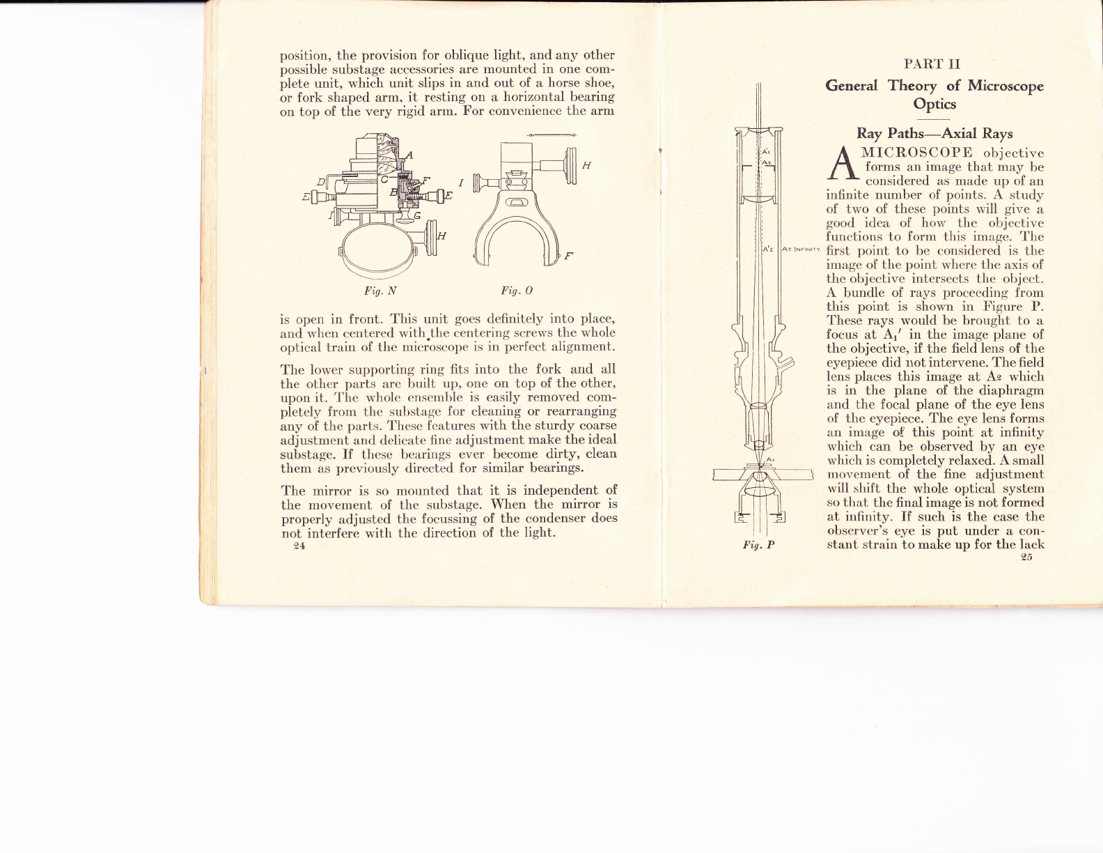
position, the provision for oblique light, and any other
possible substage accessories are mounted in one com-
plete unit, which unit slips in and out of a horse shoe,
or fork shaped arm, it resting on a horizontal bearing
on top of the very rigid arm. For convenience the arm
Fis. N Fis. O
is open in front. This unit goes definitely into place,
and when centered with.the centcring screws the whole
optical train of the rnicroscolle is in perfect alignrlent.
The lower supporl.ing ring fits into the fork and all
the othcr parts arc built up, one on top of the other,
upon it. 'l'he wholc cnscrrrble is easily removed com-
pletcly frorn thc substage for cleaning or rearranging
any of the part,s. 'l'hcse fca,tures with the sturdy coarse
adjustmcnt and dclicate fine adjustment make the ideal
substage. If thcse bearings ever become dirty, clean
them as previously directed for similar bearings.
The mirror is so mounted that it is independent of
the movement of the substage. When the mirror is
properly adjusted the focussing of the condenser does
not interfere with the direction of the light.
24
PART II
General Theory of Microscope
oji,
Ray Paths-Axial Rays
A IIICROSCOPB objective
/a forms an image that, may be
a \ con=idered as'made up of an
infinite number of points. A study
of two of these points will give a
good idea of how thc objective
functions to forrn tlris image. l'he
' first point to be considcrcd is bhe
image of the point 'lvhere the axis of
the objective intersects thc object.
A bundle of rays proceeding from
this point is shown in Figure P.
These rays would be brought to a
focus at Ar' in the image plane of
the objective, if the field lens of the
eyepiece did rrot intervene. The field
lens places this image at As which
is in the plane of the diaphragm
and the focal plane of the eye lens
of the eyepiece. The eye lens forms
an image of this point at infinity
which can be observed by an eye
which is completely relaxed. A small
rnovement of the fine adjustment
will shift the whole optical system
so that the final image is not formed
at iniinitv. If such is the case the
obscrvtrr's eye is put under a con-
stanb strain to make up for the lackFig. P

Fis. R
of proper focus of the instrument.
Thls should be avoided. It is not
always easy to know that the
instrument is properly focussed.
To test for this, gaze vacantlY out
of a window at a distant object
and then look quickly into the
microscope. If the image is
blurred at the first instant and
gradually clears, the instrument
is not properly focussed and it
should be refocussed.
Ray Paths-Field Rays
The second point to be consid-
ered is the image of a Point at
the extreme edge of the field. An
examination of Figure R shows
that in the bundle of ravs Pro-
ceeding from this object Point
therc is no symmetrY about a
<:entral ray such as existed in the
bundlc shown in Figure P. There
is, however, one ray of this bundle
that has special significance be-
cause it proceeds through t}le
olr.iective withoub anY angular
d.i'iation. This rav is ealled the
nrincinal rav and is shown as the
iet,trul ray" of the bundle. It is
directed at what maY be called
the optical center of the objec-
tive and from there toward the
Doint R,' where all t,he oLherraYs
.,f thir bundle would cross ib if it
were not for the field lens of the eyepiece. The image
point R1/ lies in the same plane as the point At'. The
field lens places this image at Rg which is at the edge
of the diaphragm and in the same plane. The eye lens
of the eyepiece deviates the principal ray so that it
crosses the axis at the point ,R D which is variously
called the Ramsden disc, exit pupil, or eyepoint. ft is
the point at which the pupil of the eye should be
placed to be able to see the whole field. The other
rays of the bundle surrounding the principal ray are
made parallel to it by the eye lens, if the microscope
is correctly focussed, and thereforc form :rn image Rr'
of Rz at infinity.
Magnifi cation-Objective
It is easy to see that the imagc point R'/ is very much
farther from the axis of the microscope than is thc object
point R1. Thus the objective forms an image which
covers considerably more area than does the object.
The magnification of the objective alone is the ratio
of the distance of Rr' from the axis to the distance of
Rr from the axis. A reference to the figure will show
that the magnification of the objective is dependent
on the distance of the optical center of the objective
from the object and also from the image. The distance
of the optical center of the objective from the image is
determined by the tube length. With the tube length
standardized the distance of the optical center of the
objective from the object is determined by the focus
of the objective only. With these data the magnification
of all our objectives is computed for a standardizcd
tube length of 160mm. It is engraved on the boots of
the objectives together with their focii and numerical
apertures. 97
Magnifi cation-Eyep iece
The eyepiece magnifies the image formed by the ob-
jective on the principle of the simple rnicroscope. An
object ten feet away appears to an observer to be a
certain size. ff the distance be reduced to five feet it
appears to be twice the size. 'I'he nearer to the observer
it is the iarger it appears. But nature has put a limit
on the accommodation of the human eye such that it
can not easily focus on an object that is closer than
ten inches from the eye. If rve wish to see an object
on a scale larger than it appears at ten inches from
the eye it is necessary to place a lens betu'een the object
and the eye to assist the accommodation. If this lens
has a focus of trvo inches the object can be placed
two inches from the eye and be seen as though it were
at infinity. In other rvords the lens does the work that
the eye can not do, and allorvs thc eye to see the object
'lvith no effort at acconlnodltion. 'I'lre object being
only trvo int:hes frorn tlrc cyc il,l)l)cars to be five times
as large as tlr<-ngh il" rvcrc vir:rvcd at the nearest pos-
sible disl-rlnr:e by t,lrc rrna,i<lctl cyc. Thus the lens is
said to ha,vc :r, rnagrri{i<'rr,t,ion of five. It is on this basis
that our eycyriuts ilxr r:urrrpnted and marked for mag-
nification.
Magnifi cation-Compound Microscope
The total magnificll"ion <if a compound microscope is
the product of thc magnification of the objective and
eyepiece. Thus if an oil immersion objective and 10x
eyepiece is used the total magnification is 980, found
by multiplying 98, the magnification of the objective
alone, by 10, the magnification of the eyepiece.
8A
Defi nition-Spherical Aberration
In explaining the paths of rays through a microscope
'objective, it was assumed that the rays crossed at a
point to form an image. This is never strictly true and
is approximated only when the correction for spherical
aberration is good. If the correction for spherical aber-
ration is perfect, the rays of a bundle are so directed
that they would cross at a point if it were not for the
fact that light is a wave motion. Due to this fact they
do not cross at an exact point, but jostle each other
near the crossing point in such a way that the otherwise
point image is spreerd out into a small disc of measurable
dimensions. }'urthermore, this central disc is surrounded
by a series of concentric rirrgs of alternate liglrt and
dark. This whole pattern is called a difiraction pattern.
When the correction is good these surrounding rings
are faint and diminish in width so rapidly from the
center out, that only one or two of them can be seen
by the most critical test. If, however, the correction
is poor the rings are bright and broad. The central
disc remains the same size, but a large portion of the
Iight that should be concentrated in this disc is lost
to the surrounding rings. Since the central disc is the
only portion of the whole pattern that goes to make
up the image, this means that the image will be faint
and that the lost light will be spread over the surround-
ing area and tend to haze the image of nearby points.
Thus contrast in the image is destroyed and it appears
hazy and washcd out. This is the true interpretation
of definition. It is only a matter of contrast. The pro-
portion of light conccntrated in the central disc de-
termines the quality of the <lefinition. ss
I

Defi nition-Chromatic Aberration
The general features of these diffraction patterns will
vary with the correction for color. If the axial correc-
tion is not good the rings will occur at different points
along the axis for different colors. Their size and relative
concentration of light in the central disc will also vary
with color if the so-called chromatic variation of spher-
ical aberration is not corrected. ft is evident that the
contrast which determines the definition can be lost
quite as easily by a poor correction for color as by a
poor correction for spherical aberration. It is not possi-
ble to obtain a perfect correction for color because of
the limitations of manufacture of optical glass. The
usual type of lens is corrected for two colors on the
axis and spherical aberration for one color, and a close
approach to a correction for spherical aberration for
the other colors. Achromatic objectives have such a
correction. The lack of perfect color correction is evi-
denced by a small fringe of color around a dark object,
especially when obliquc light is uscd. It is possible with
the aid of the ncwcst glasscs and the mineral fluorite
to correr:t for thrcc r:olors on the axis and to correct
the spherical abcrration for two colors. Such a com-
bination must of nct:cssity be very complicated. It is
termed an apochrornatic objective and is the finest type
obtainable. With such a lens no color fringe is noticea-
ble except undcr the most trying of conditions and
even then it is faint and narrow. The apochromatic
objectives are extensively used for micro-photography
because of their more perfect color correction. It forms
an image that is extremely pleasing to the eye in its
crispness of detail and faithfulness of reproduction of
color.
30
,"*
Resolving Power-What It Is
There is a conception among some users of the micro-
scope that magnification and definition are of para-
mount importance. This is not strictly true, for there
is another requirement that is more important than
either of these. This is resolving power, the ability
to pick out and recognize fine detail. As an example
suppose we consider a piece of fine cloth having a pat-
tern woven in it. Suppose that this cloth is held at
such a distance from the eye that the pattern is not
distinguishable. A slight magnification will allow the
pattern to be seen clearly and easily. Now suppose we
magnify it a thousand times, and that the definition
is good enough so that the pattern is seen clearly and
distinctly, but on a very much larger scale. On first
consideration this may seem su{Iicient. On further
thought, however, it appears that at a thousand mag-
nification the threads of which the cloth is woven should
appear to be more than an inch broad, and the spaces
between them sufficiently wide to be seen easily. The
ability to see these fine details in the object is called
resolving power. However, the image may show no
indication of a thread structure due to insufficient
resolving power. Thus the optical system, having good
definition, and more than enough magnification, fails
completely to give a true interpretation of the object.
This illustration is given to show that there is no con-
nection between resolving power and magnification or
definition. It is a thing quite apart from other proper-
ties of an optical system and for the finest microscope
work is by far the most important.
Resolving Power-Oil Immersion Objectives
A quantity called the numerical aperture is the mcts-
ure of the resolving power of a microscope objectivc.
It
'I
{
I
I'
'l\
I
The numerical aperture is expressed by the equation
NA: n sin a
where n is the lowest index of refraction between the
olject and the objective, and a is the angle between
the extreme ray of the axial bundle and the axis, shown
i! Figure P. This expression that is arbitrarily called
the numerical aperture is derived from a mathematical
study of resolving power. It is beyond the scope of this
book to give the derivation here. The reason-why the
lowest index of refraction between the object atrd the
front- lens of the objective enters into th-e expression
will be touched on under the heading of " Resolving
Power from the Standpoint of the Diffraction Theory."*
It is at once apparent that in order to secure a Liglt
resolving power, it is necessary to design the objective
!9 lake in a large angle. There are, however, practical
limits be_yond which it is not advisable to go. This angle
can not be much more than 60o. For 60" the numerical
aperture would be .86 if the lowest index medium
betwe_en the object and the objective were air having
an index of rcfraction of onc. ff, howcvcr, the objective
were designed to havc oil of an indcx of refraciion of
1.52 between thc objcct:rnd Lhc obje<:tive, the numerical
a_per'rrre woukl bc .86.1.52,:l.30.This is the theory
t\at led to the dr:sign of the oil immersion objectives.
The use of the oil irnmersion principle multi$lies the
highest numerical aperture otherwiie obtainable by
1.52, the index of the oil. This is only true, howevei,
if a condenser of at least the same numerical aperture
as the objective is used, and if an oil contact -is used
between the condenser and the sl'ide.
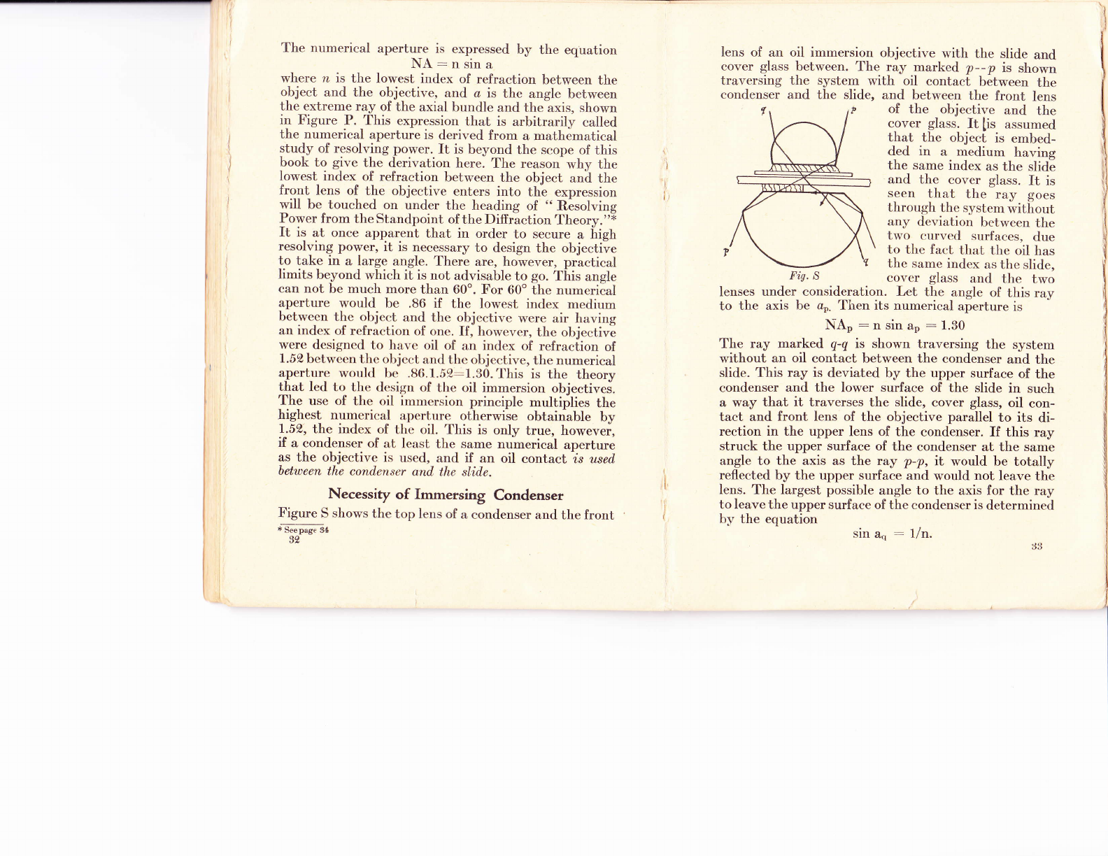
Necessity of Immersing Condenser
Figure S shows the top lens of a condenser and the front
* S* pug" 3+
aa
Iens of an oil immersion objective with the slide and
cover glass between. The ray marked p--p is shown
traversing the system with oil contact between the
condenser and the slide, and between the front lens
r of the objective and the
cover glass. It [is assumed
thal thc ob.ject is embed-
ded in a medium having
the same index as the slide
and the cover glass. ft is
seen that the ra.y goes
through Lhc s.yslem without
any deviation between the
two curved surfaces, due
to thc fact that the oil has
the same irrdex as the slide,
Fis. S cover glass and the two
Ienses under consideration. Let the angle of this ray
to the axis be ao. Then its numerical aperture is
NAe:nsinao:l'30
The ray marked q-q is shown traversing the system
without an oil contact between the condenser and the
slide. This ray is deviated by the upper surface of the
condenser and the lower surface of the slide in such
a way that it traverses the slide, cover glass, oil con-
tact and front lens of the objective parallel to its di-
rection in the upper lens of the condenser. If this ray
struck the upper surface of the condenser at the same
angle to the axis as the ray ?-p, it would be totally
reflected by the upper surface and v'ould not leave the
lens. The largest possible angle to the axis for the ray
to leave the upper surface of the condenser is determinecl
bY the equation sin an : r/n.
Thus the largest numerical aperture possible under
these conditions is
NAq:nsinao:n/n:1.0
It is evident that a large pait of the benefit of having
an oil contact between the object and the objective i!
Iost by not having an oil contact between ihe corr-
d-enser and the slide, even though it is retained between
the cover glass and the objectlve.
Resolving Power-From Standpoint of
Diftaction Theory
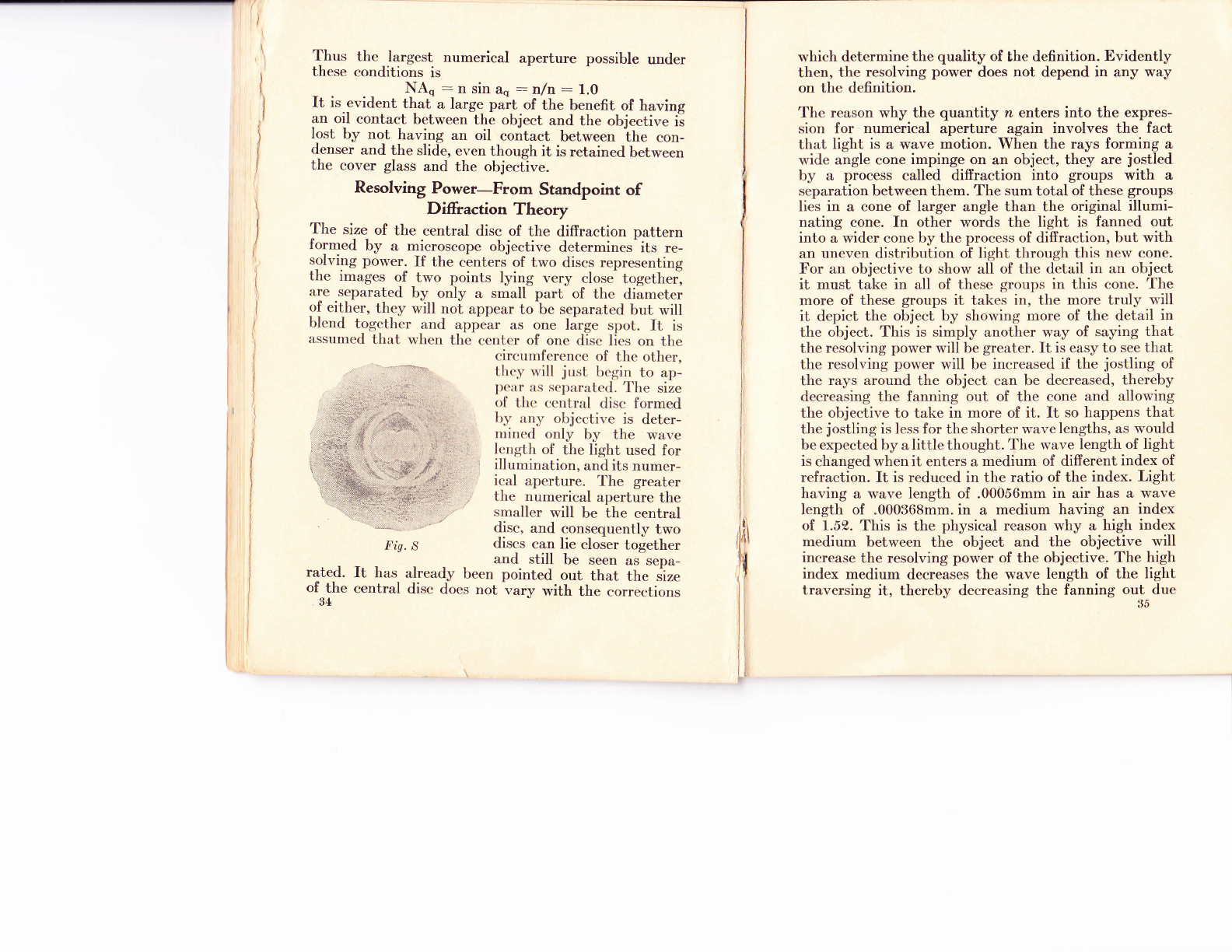
The size of the central disc of the diffraction pattern
formed by a microscope objective determines-its re-
solving power. If the centers of two discs representing
the images of two points lying very close together]
are separated by only a small part of the diameter
of either, they will not appear to be separated but will
blend together and appear as one large spot. It is
assurned that u'hen the centel of one disc lics on the
circurnfcrcncc of thc other,
I.lrcv will .jrrst, bcgin to ap-
lx':rr :r.s sclrirnlt.etl. l'he size
ol' [,lrc ccntral disc formed
lrv rLrry objective is deter-
rrinecl only by the *'ave
, lcngth of the light used for
I illumination, and its numer-
ical aperture. The greater
,, the numerical aperture the
smaller will be the central
disc, and consequently two
discs can lie closer together
and still be seen as sepa-
rated. It has already been pointed out that the size
of the central disc does not va,rv with the coner.tionq
34 vary with the corrections
which determine the quality of the definition. Evidently
then, the resolving power does not depend in any way
on the definition.
The reason why the quantity n enters into the expres-
sion for numerical aperture again involves the fact
that light is a wave motion. When the rays forming a
wide angle cone impinge on an object, they are jostled
by a process called diffraction into groups with a
separation between them. The sum total of these groups
lies in a cone of larger angle than the original illumi-
nating cone. In other words the light is fanned out
into a wider cone by the process of diffraction, but with
an uneven distribution of light through this new cone.
For an objective to show all of the detail in an object
it must take in all of these groups in this cone. 'I'he
more of these groups it takes in, the more truly will
it depict the object by showing more of the detail in
the object. This is simply anotherway of saying that
the resolving power will be greater. It is easy to see that
the resolving power will be increased if the jostling of
the rays around the object can be decreased, thereby
decreasing the fanning out of the cone and allowing
the objective to take in more of it. It so happens that
the jostling is less for the shorter wave lengths, as would
be expected by a little thought. The wave length of light
is changed when it enters a medium of different index of
refraction. It is reduced in the ratio of the index. Light
having a wave length of .00056mm in air has a wave
length of .000368mm. in a medium having an index
of 1.52. This is the physical reason why a high index
medium between the object and the objective will
increase the resolving power of the objective. The high
index medium decreases the wave length of the light
traversing it, thereby decreasing the fanning out-due
li\
ll
1,
l,
I
li

to difiraction around the object i and therefore allows
an objective of a given angle to take in more of this
diffra.ction pattern. The objective can then form an
image that includes more of the fine detail of the object,
which means that its resolving power is greater. It
should be remembered that this high index medium
must lie in an unbroken chain between the object and
the objective, to prevent the fanning out before the
light enters the objective. The above line of reasoning
also serves to explain why the use of short wave lengths
such as the ultra violet increases the resolving power.
The shortest distance between two objects that can
be shown as separated by a microscope objective used
with a condenser that is properly immersed, is given
by the expression 2,/NA, where 2, is the wave length
of light used for illuminating the object. Without a
condenser this becomes 2,/NA. The wave length of
the brightest part of the spectrum is about .00056mm.
This is the value used in the following table.
I\tumerical Limit of Resolut'ion I''imit of Resolution
Aperlure Witlnut condntsr:r With Condenser
.10 .0056 mrrt. .0028 mm.
.25 .00224 rnm. .00112 mm.
.50 .00112 mm. .00056 mm.
.66 .00085 mm. .000425 mm.
.85 .00066 mm. .000330 mm.
.95 .00059 mm. .000295 mm.
1.00 .00056 mm. .000280 mm.
1.25 .00045 mm. .000225 mm.
1.30 .00043 mm. .000215 mm.
The above table gives the smallest distance betwecn
two objects that can be seen as separate objects when
viewed'under the conditions indicated. It should be
36
rrotcd that this distance is exactly halved when it <'ott-
rltrrrscr is used. This ernphasizes the necessity of rrsirrg
ir, r.ondenser when high resolving power is rtxluit't'rl.
'l'lris limit of resolution is not dependcnt on thc Irr:r.g-
nilication providing sufficient magnification is uscd. I'irr
irrst.llnce, no amount of magnification will show l,lrrr
scparation between two objects that are separated by
.(X)0f] mm. unless an objective of at least .95 numeri<:ill
tperture is used, with a condenser.
Proper Magnification
It is not necessary to use a magnification greatcr thir.n
enough to depict clearly to the eye the finest <let,rril
rcsolvable by the objective. A greater magnifica.liorr
will show no more detail and will materially dccrt'asc
the illumination. It will also tend to decreasc l,lrc
contrast of the image, so that the ease with wlriclr
an object can be studied will be decreased rather tltirn
increased by increasing the magnification above :r crt'r-
tain advisable maximum. The field and the depth ol'
focus both decrease vrith an increase of magnificatiorr.
The rnagnification should, therefore, be as low as pos-
sible. The maximum useful magnification can be conl-
puted by dividing .3mm. by the limit of resoluliorr
of the objective used, given in the above table. 'I'hus
for an objective having a numerical aperture of l.ll0
:rnd a limit of resolution of .000215, the greatest t,otirl
magnification that should be used is 1400. This irrrli-
t':rtcs a 15r eyepiece with a 1.8 mm. focus object.ivt'.
'l'his represents the highest magnification that shorrkl
t:vcr be used except in very unusual cases. I'or ntosl,
work the proper magnification is much less.
Depth of Focus
Assrrming the samc qu:rlit.y of correction and thc sn,rrrc
lnagnifi<,a.tion, thc illrrrrrirrrr.l.ion varies as the squart'nof
This manual suits for next models
1
Popular Microscope manuals by other brands

Explore One
Explore One 900x instruction manual

Westfalia
Westfalia 81 51 19 instruction manual

Denville Scientific
Denville Scientific M2100 Series Operation manual

Motic
Motic SMZ168 Series instruction manual

3B SCIENTIFIC PHYSICS
3B SCIENTIFIC PHYSICS 500 1013146 instruction manual

Meiji Techno
Meiji Techno RZ Series instruction manual


