Leica Z6 APO User manual

Leica
Z6 APO A &
Z16 APO A
User manual

2 Leica Z6 APO A & Z16 APO A – User manual
Overview of the instrument
Fig. 1 Motorized Leica Z16 APO A and Z6 APO A zoom systems with integrated, motorized
fine focusing, integrated, motorized iris diaphragm and planapochromatic objective.
2
1
1Leica Z16 APO A zoom system
2Leica Z6 APO A zoom system
3Planapochromatic objective
4M12 device connection (Lumberg)
4
4
3

Leica Z6 APO A & Z16 APO A – User manual 3
Dear User,
Thank you for your faith in our product. We hope
your work with it is both enjoyable and successful.
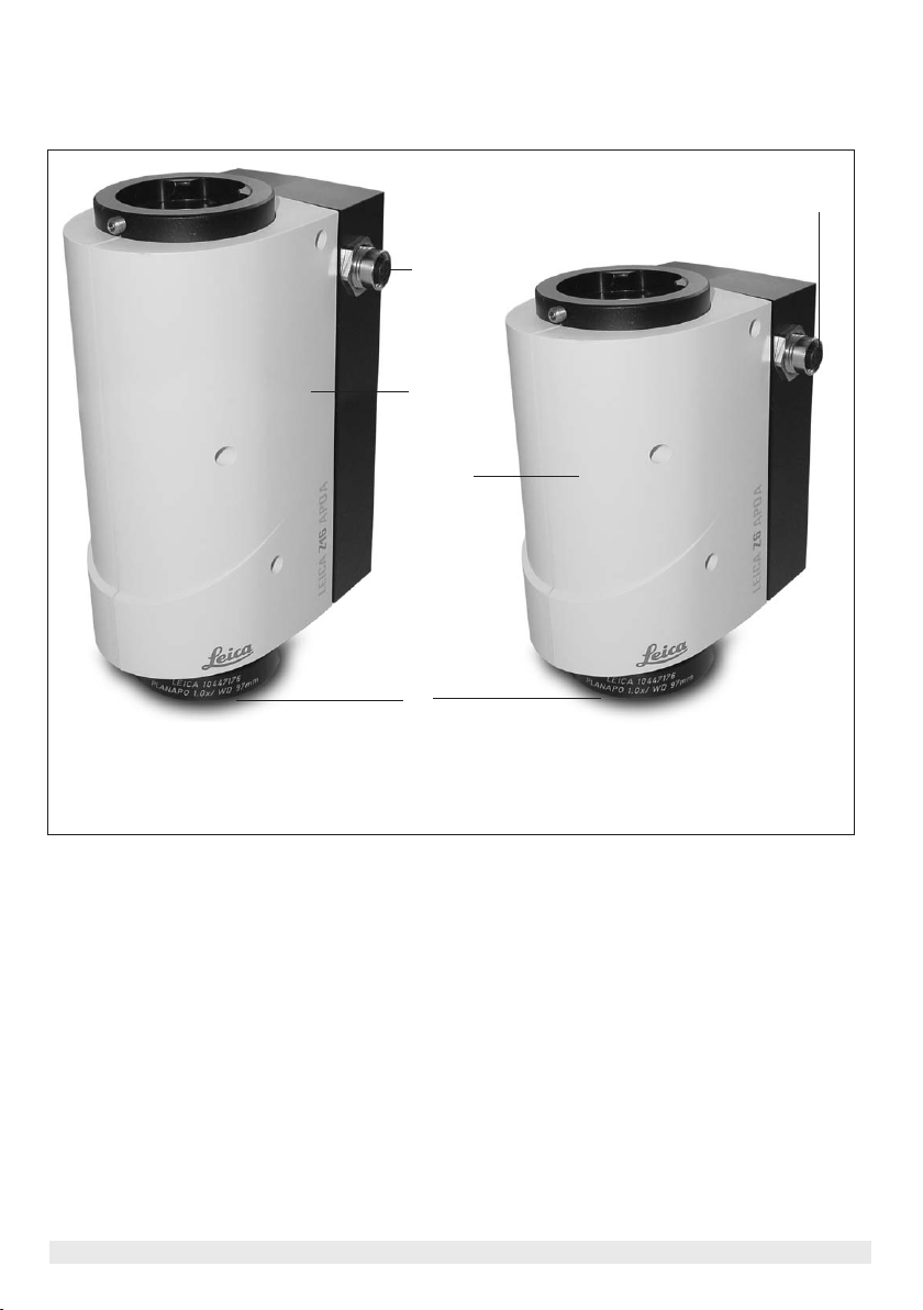
The Leica Z6 APO A and Z16 APO A from Leica
Microsystems are the only fully apochromatically
corrected motorized zoom systems on the market,
and are superior to other zoom systems in con-
trast, image sharpness, color fidelity and image
precision. The Leica Z6 APO A and Z16 APO A are
exceptionally well suited to high-precision inspec-
tions throughout the entire manufacturing
process, all the way to the integration of them into
machine vision systems, as well to scientific and
medical applications.
Both zoom systems feature motorized zoom, iris
diaphragm and fine focusing. This allows for
automating many inspection and documentation
tasks and repeating them via PC control. Further-
more, you can create complete single measure-
ment and testing stations tailored to your custom
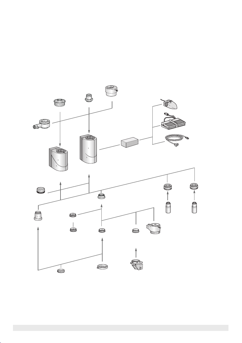
needs. The new zoom systems include the widest
line of accessory products to meet every imagin-
able examination, training, and documentation
task. With compatible stands, illuminators, binocu-
lar tubes and video/phototubes, motorized focus,
modern CCD cameras, and much more, the
Leica Z6 APO A and Z16 APO A are suitable for
video inspection, measurement, documentation
and analysis tasks in the QA lab, just as they are
suited for biology, geology, histology, criminology
and training.
In developing our instruments, we place great
value on simple, self-explanatory operation. How-
ever, please take the time to read the user manual
and the operating safety information to become
familiar with the advantages and options of your
Leica Z6 APO A and Z16 APO A zoom systems, so
that you can use them optimally and safely.
Should you have any questions, please consult
your local Leica representative. You will find the
address of the closest local representative as well
as valuable information about products and ser-
vices from Leica Microsystems on our homepage at
www.leica-microsystems.com
We are gladly at your service. Customer service is
a big thing with us. Not only before the sale, but
afterwards as well.
Leica Microsystems (Switzerland) Ltd
Stereo & Macroscope Systems
www.stereomicroscopy.com

4 Leica Z6 APO A & Z16 APO A – User manual
Contents
Page
1. Safety concept . . . . . . . . . . . . . . . . . . . . . . . . . . . . . . . . . . . . . . . . . . . . . . . . . . . . . . . . . . . . . . 6
1.1 The user manual . . . . . . . . . . . . . . . . . . . . . . . . . . . . . . . . . . . . . . . . . . . . . . . . . . . . . . . . . . . . 6
1.1.1 Diagrams . . . . . . . . . . . . . . . . . . . . . . . . . . . . . . . . . . . . . . . . . . . . . . . . . . . . . . . . . . . . . . 6
1.1.2 Symbols used . . . . . . . . . . . . . . . . . . . . . . . . . . . . . . . . . . . . . . . . . . . . . . . . . . . . . . . . . . 7
1.2 Safety instructions . . . . . . . . . . . . . . . . . . . . . . . . . . . . . . . . . . . . . . . . . . . . . . . . . . . . . . . . . . 7
2. Assembly . . . . . . . . . . . . . . . . . . . . . . . . . . . . . . . . . . . . . . . . . . . . . . . . . . . . . . . . . . . . . . . . . 10
2.1 Zoom systems . . . . . . . . . . . . . . . . . . . . . . . . . . . . . . . . . . . . . . . . . . . . . . . . . . . . . . . . . . . . . 11
2.2 Assembly of zoom system and objective . . . . . . . . . . . . . . . . . . . . . . . . . . . . . . . . . . . . . . . 11
2.3 Tubes, carriers . . . . . . . . . . . . . . . . . . . . . . . . . . . . . . . . . . . . . . . . . . . . . . . . . . . . . . . . . . . . . 12
2.3.1 Camera assembly with AS video/phototube . . . . . . . . . . . . . . . . . . . . . . . . . . . . . . . 14
2.3.2 Camera assembly with A video/phototube . . . . . . . . . . . . . . . . . . . . . . . . . . . . . . . . 16
2.3.3 Camera assembly with Y tube . . . . . . . . . . . . . . . . . . . . . . . . . . . . . . . . . . . . . . . . . . . 17
2.3.4 Camera assembly with Y tube and HD video/phototube . . . . . . . . . . . . . . . . . . . . . 18
2.3.5 Assembly of binocular tubes on Y tube . . . . . . . . . . . . . . . . . . . . . . . . . . . . . . . . . . . 20
2.4 Attachment to stands . . . . . . . . . . . . . . . . . . . . . . . . . . . . . . . . . . . . . . . . . . . . . . . . . . . . . . . 22
2.4.1 Incident and transmitted light stands with column 500 mm . . . . . . . . . . . . . . . . . . 23
2.4.2 Swinging-arm stands, OEM . . . . . . . . . . . . . . . . . . . . . . . . . . . . . . . . . . . . . . . . . . . . . 24
2.4.3 Swinging-arm stand ESD . . . . . . . . . . . . . . . . . . . . . . . . . . . . . . . . . . . . . . . . . . . . . . . .25
2.4.4 Large swinging-arm stand . . . . . . . . . . . . . . . . . . . . . . . . . . . . . . . . . . . . . . . . . . . . . . 25
2.5 OEM . . . . . . . . . . . . . . . . . . . . . . . . . . . . . . . . . . . . . . . . . . . . . . . . . . . . . . . . . . . . . . . . . . . . . . 25
2.6 Adaptation to reprocopy stand . . . . . . . . . . . . . . . . . . . . . . . . . . . . . . . . . . . . . . . . . . . . . . . 25
2.7 Electrical connections . . . . . . . . . . . . . . . . . . . . . . . . . . . . . . . . . . . . . . . . . . . . . . . . . . . . . . .26
2.8 Control system . . . . . . . . . . . . . . . . . . . . . . . . . . . . . . . . . . . . . . . . . . . . . . . . . . . . . . . . . . . . .26
2.9 Illumination . . . . . . . . . . . . . . . . . . . . . . . . . . . . . . . . . . . . . . . . . . . . . . . . . . . . . . . . . . . . . . . . 27
3. Operation . . . . . . . . . . . . . . . . . . . . . . . . . . . . . . . . . . . . . . . . . . . . . . . . . . . . . . . . . . . . . . . . . 28
3.1 Zoom systems, operating principle . . . . . . . . . . . . . . . . . . . . . . . . . . . . . . . . . . . . . . . . . . . 28
3.2 Starting up . . . . . . . . . . . . . . . . . . . . . . . . . . . . . . . . . . . . . . . . . . . . . . . . . . . . . . . . . . . . . . . . .28
3.2.1 Disconnecting from the power supply . . . . . . . . . . . . . . . . . . . . . . . . . . . . . . . . . . . . .28
3.3 Motorized functions . . . . . . . . . . . . . . . . . . . . . . . . . . . . . . . . . . . . . . . . . . . . . . . . . . . . . . . . .28

Leica Z6 APO A & Z16 APO A – User manual 5
3.4 UMC handheld controller . . . . . . . . . . . . . . . . . . . . . . . . . . . . . . . . . . . . . . . . . . . . . . . . . . . . 28
3.4.1 Changing button assignment . . . . . . . . . . . . . . . . . . . . . . . . . . . . . . . . . . . . . . . . . . . . 29
3.4.2 Zoom (change magnification): Z and ZW . . . . . . . . . . . . . . . . . . . . . . . . . . . . . . . . . .29
3.4.3 Fine focusing: FF and FFW . . . . . . . . . . . . . . . . . . . . . . . . . . . . . . . . . . . . . . . . . . . . . . 30
3.4.4 Focusing with motor focus: F . . . . . . . . . . . . . . . . . . . . . . . . . . . . . . . . . . . . . . . . . . . . .30
3.4.5 Iris diaphragm: I . . . . . . . . . . . . . . . . . . . . . . . . . . . . . . . . . . . . . . . . . . . . . . . . . . . . . . . 30
3.4.6 Storing current positions: Set . . . . . . . . . . . . . . . . . . . . . . . . . . . . . . . . . . . . . . . . . . . . 31
3.5 Foot switch . . . . . . . . . . . . . . . . . . . . . . . . . . . . . . . . . . . . . . . . . . . . . . . . . . . . . . . . . . . . . . . .31
3.6 Working with a binocular tube . . . . . . . . . . . . . . . . . . . . . . . . . . . . . . . . . . . . . . . . . . . . . . . 32
3.6.1 Adjusting diopter settings . . . . . . . . . . . . . . . . . . . . . . . . . . . . . . . . . . . . . . . . . . . . . . . 32
4. Appendix . . . . . . . . . . . . . . . . . . . . . . . . . . . . . . . . . . . . . . . . . . . . . . . . . . . . . . . . . . . . . . . . . . 34
4.1 Dimensions . . . . . . . . . . . . . . . . . . . . . . . . . . . . . . . . . . . . . . . . . . . . . . . . . . . . . . . . . . . . . . . . 34
4.1.1 Dimensions of zoom systems . . . . . . . . . . . . . . . . . . . . . . . . . . . . . . . . . . . . . . . . . . . .34
4.1.2 Dimensions of objectives . . . . . . . . . . . . . . . . . . . . . . . . . . . . . . . . . . . . . . . . . . . . . . . .35
4.1.3 Dimensions of tubes . . . . . . . . . . . . . . . . . . . . . . . . . . . . . . . . . . . . . . . . . . . . . . . . . . . .36
4.1.4 Dimensions of carriers . . . . . . . . . . . . . . . . . . . . . . . . . . . . . . . . . . . . . . . . . . . . . . . . . .38
4.1.5 Dimensions of adapters . . . . . . . . . . . . . . . . . . . . . . . . . . . . . . . . . . . . . . . . . . . . . . . . .40
4.2 Technical data . . . . . . . . . . . . . . . . . . . . . . . . . . . . . . . . . . . . . . . . . . . . . . . . . . . . . . . . . . . . . .41
4.3 Electrical connection diagram . . . . . . . . . . . . . . . . . . . . . . . . . . . . . . . . . . . . . . . . . . . . . . . 44
4.4 Visual optical data with Y tube . . . . . . . . . . . . . . . . . . . . . . . . . . . . . . . . . . . . . . . . . . . . . . .45
4.5 Expansion diagram . . . . . . . . . . . . . . . . . . . . . . . . . . . . . . . . . . . . . . . . . . . . . . . . . . . . . . . . . 46
Contents

6 Leica Z6 APO A & Z16 APO A – Safety concept
1. Safety concept
1.1 The user manual
Included with your Leica Z6 APO A and Z16 APO A
zoom systems is an interactive CD-ROM with all
pertinent user instructions in German, English,
French, Spanish, Italian, Portuguese, Dutch, Dan-
ish, Swedish, Finnish, and Greek. Keep it in a safe
place, and readily accessible to the user. User
manuals and updates are also available for you to
download and print from our web site at
www.stereomicroscopy.com.
This operating manual describes the special func-
tions of the Leica Z6 APO A and Z16 APO A zoom
systems and contains important instructions for
their operational safety, maintenance, and acces-
sories. The Leica Z6 APO A and Z16 APO A are
zoom systems which can be expanded in a modu-
lar system, allowing an almost unlimited range of
individual equipment configurations. The identical
modules, such as stands, binocular tubes, acces-
sories, etc. are described in User Manual M2-105-0
for Leica M stereomicroscopes, which also con-
tains additional safety instructions pertaining to
accessories and electrical accessories, as well as
care instructions.
Special manuals are provided for the following
accessories:
– User Manual M2-267-1 for the motorized focus
system.
– User Manual M2-216-2 for the Leica HL RC™
transmitted-light base
– User Manual M2-416-2 for UMC handheld
controller
Before installing, operating or using the
instruments, read the user manuals listed above.
In particular, please follow all safety instructions.
To maintain the unit in its original condition and to
ensure safe operation, the user must follow the
instructions and warnings contained in these user
manuals.
1.1.1 Diagrams
(1.5) Numbers in parentheses within the descrip-
tions pertain to diagrams and the items in the dia-
grams. Example (1.2): Figure 1is found on Page 2
and item 2 is the zoom system Leica Z6 APO A.

Leica Z6 APO A & Z16 APO A – Safety concept 7
1.1.2 Symbols used
Warning of a danger
This symbol indicates especially important infor-
mation that, if not observed,
– can cause hazards to personnel,
– can lead to functional disturbances and dam-
aged instruments.
Warning of hazardous electrical voltage
This symbol indicates especially important infor-
mation that, if not observed,
– can cause hazards to personnel,
– can lead to functional disturbances and dam-
aged instruments.
Danger due to hot surface
This symbol warns against touching hot surfaces,
e.g. those of light bulbs.
Important information
This symbol indicates additional information or
explanations that intend to provide clarity.
Action
This symbol refers to actions described in the
text that are to be carried out.
Explanatory notes
• This symbol indicates additional notes and
explanations provided in the text.
1.2 Safety instructions
Description
The Leica Z6 APO A and Z16 APO A zoom systems
are optical systems with 6.3:1 or 16:1 motorized
magnification changer and a central beam path.
The most precise information can be obtained
thanks to the parallax free observation. Measure-
ments, adaptation tasks and evaluations become
more precise; more high-quality information is
obtained in photography and image processing.
The vertical beam path, combined with motorized
functions, is predestined for digital imaging with
multi-focus programs. Polarized optical examina-
tions provide true polarization colors, and the
geometric layers of flat, highly reflective objects
such as wafers appear without distortion when
using coaxial illumination.
Leica Z6 APO A and Z16 APO A feature an exten-
sive accessories program in a modular design,
such as objective, carrier, video/phototubes,
stands, binocular tubes, eyepieces and much
more (see expansion diagram p. 46).
Permitted uses
With the motorized Leica Z6 APO A and Z16 APO A
zoom systems and the apochromatic objectives,
entire objects can be inspected and documented
without distortion and sequences of operation can
be automated. As high-performance optical equip-
ment, they lend themselves to use with measure-
ment and testing systems including vision tech-
nology systems, and for high-end laboratory work-
stations.

8 Leica Z6 APO A & Z16 APO A – Safety concept
Non-intended use
If the Leica Z6 APO A or Z16 APO A, its components
or accessories are used other than as described in
the user manual, injury or property damage may
occur. Never:
– install other plugs or cables.
– change, rebuild or take apart parts, if not
specifically instructed to do this in the manual.
– allow unauthorized persons to open parts.
– use the Leica Z6 APO A and Z16 APO A for
examining, or operating on the human eye.
The devices and accessories described in this
operating manual have been tested for safety and
potential hazards. The responsible Leica affiliate
must be consulted whenever the device is altered,
modified or used in conjunction with non-Leica
components that are outside of the scope of this
manual.
Unauthorized alterations to the device or noncom-
pliant use shall void all rights to any warranty
claims!
Responsibilities of the person(s) in charge of
instrument
Ensure that
– the Leica Z6 APO A and Z16 APO A and acces-
sories are operated, maintained and repaired
by authorized and trained personnel only.
– the operating personnel has read, understands,
and is observing these instructions as well as
those listed on page 6, and, in particular, the
safety instructions.
Place of use
– The Leica Z6 APO A and Z16 APO A may only be
operated in closed, dust-free rooms at +10˚ C to
+40˚ C. Ensure that the room is free of oil and
chemical fumes and extreme humidity.
– Electrical components must be assembled at
least 10 cm away from the wall and from flam-
mable substances.
– Large temperature fluctuations, direct sunlight
and vibrations should be avoided. These condi-
tions can distort measurements and micro-
graphic images.
– Optical systems in warm and warm-damp
climatic regions require special care in order
to prevent the build up of fungus.
Disposal
The products described here must be disposed
off in accordance with applicable local laws and
regulations.
Legal requirements
Adhere to general and local regulations relating to
accident prevention and environmental protec-
tion.
Conformity with European Community directive
The Leica Z6 APO A and Z16 APO A and their
accessories are constructed based on the state of
the art of technology and are provided with an EU
Declaration of Conformity.

Leica Z6 APO A & Z16 APO A – Safety concept 9
Health risks
Workplaces with optical systems facilitate
and improve the viewing task, but they also
impose high demands on the eyes and holding
muscles of the user. Depending on the duration of
uninterrupted work, asthenopia and muscu-
loskeletal problems may occur. For this reason,
appropriate measures for reduction of the work-
load must be taken:
– optimal arrangement of workplace, work
assignments and work flow (changing tasks
frequently).
– thorough training of the personnel, giving
consideration to ergonomic and organization
aspects.
The ergonomic optics concept and the design of
Leica optics systems aim to limit the strain on the
user to the lowest possible level. If you wish to
equip your zoom system with one of our binocular
tubes, we offer ErgoTubes®and ErgoModules®,
which compensate for the varying design heights
of the equipment, accessories and working dis-
tances, and for the variation of human height of its
users. If you have problems with the viewing con-
figuration, ask your Leica consultant for the most
ergonomic Leica solutions.
Direct contact with eyepieces is a potential
transmission method for bacterial and viral infec-
tions of the eye. Users should be made aware of
the potential risk of infection. The risk can be kept
to a minimum by using personal eyepieces for
each individual or detachable eyecups.
Repairs and servicing
– Only Leica Microsystems-trained service tech-
nicians, or technical specialists assigned by
the person in charge of the instrument, are
permitted to carry out repairs.
– Only original Leica Microsystems spare parts
may be used.
– Unplug the power cable before opening voltage
carrying parts.
Touching the live circuit can cause injury.
Transport
– Use the original packaging for shipping or
transporting the zoom systems and their acces-
sory components.
– In order to prevent damage from vibrations,
disassemble all moving parts that (according to
the user manual) can be assembled by the cus-
tomer and pack them separately. These include
the objective, video/phototube, carrier, binocu-
lar tube, eyepieces, etc.
Integration in third-party products
When installing Leica products into third-party
products, note the following: The manufacturer of
the complete system or its dealer is responsible
for following all applicable safety instructions,
laws and guidelines.

10 Leica Z6 APO A & Z16 APO A – Assembly
06.04
10 447 204
10 447 109
10 447 128
10 447 170
10 447 175
Planapo
10 445 352
11 506 084
10x
11 506 057
20x
10 447 179
10 447 085
10x
10 447 086
20x
10 447 206
10 411 597 100mm
10 441 787 150mm
10 431 692 175mm
10 382 162 200mm
Achromat
10 445 198
10 445 156
10 411 589
1x
Achromat
Achromat
10 447 083
10 447 177
0.5x
10 446 360
0.8x
10 447 176
1x
10 447 178
2x
10 315 306
10 422 564
0.32x
10 422 563
0.5x
10 445 201
0.63x
HR DM
Z6 APO A
10 446 368
Z16 APO A
10 446 369
10 446 172
10 382 172
f = 400mm
35 000 011
f = 800mm
35 000 013
f = 1200mm
Achromat
LWD
10 447 080
10 446 182
10 446 260 RS 232
Distribution box
2. Assembly
Diagram 1: Zoom systems, objectives and accessories

Leica Z6 APO A & Z16 APO A – Assembly 11
Fig. 2 Assembly of zoom system and objective:
Leica Z16 APO A and
Z6 APO A zoom
systems, mounted objective.
1Leica Z16 APO A zoom system
2Leica Z6 APO A zoom system
3Objectives
2.1 Zoom systems
For every zoom system, please order a
Leica Z6 APO A and Z16 APO A objective.
The basic components–the zoom system and objec-
tive–can be combined in modular fashion with vari-
ous tubes, carriers, stands, focusing drives, binocu-
lar tubes, illuminators and accessories for digital
imaging and expanded into complete workstations.
Accessories that are also used for Leica M series
stereomicroscopes are listed in the User Manual for
Leica M stereomicroscopes, M2-105-0.
Either the integrated clamping screws or an Allen
key is necessary for assembly; these are included
in delivery.
2.2 Assembly of zoom system and
objective
• We recommend using the 1×, 2×, 0.8×, 0.5×
planapochromatic objectives, in order to take
advantage of the high performance of the
planapochromatic zoom system.
• You can attach the quarter-wave plate for
coaxial illumination, the analyzer for polariza-
tion or the ring illuminator to the planapochro-
matic objectives.
• Also available are the M series 0.63×, 0.5×,
0.32×achromatic objectives, which can be
attached to the zoom using an adapter (see
assembly diagram on page 12).
• You can attach the vertical illuminator or the
attachment for incident/oblique observation
to the achromatic objectives.
1
2
3
• For magnifications in the microscopic range,
DM and HR objectives are available, which can
be attached to the zoom with an adapter (see
assembly diagram on page 10). DM and HR
objectives are controlled via the motorized fine
focusing.
Objective / zoom system
The zoom system contains an integrated motor-
ized zoom, integrated motorized fine focusing and
motorized iris diaphragm.
Fastening the planapochromatic objective (2.3).

12 Leica Z6 APO A & Z16 APO A – Assembly
06.04
A
10 447 128
AS
10 447 204
10 447 196
10 445 930
1x
10 446 345
10 446 344
10 446 343
10 446 394
Objectives see page 10
C-Mount, CCD camera
1”, 2/3”, 1/2”, 1/3”
Leica DC camera
Leica DFC camera
CCD camera
Leica
MPS30 / MPS60
SLR camera
Z16 APO A
10 446 369
Repro stand
adapter
10 446 307
0.8x
10 446 261
2/3”, 0.63x
10 445 929
1/2”, 0.5x
10 445 928
1/3”, 0.32x
Z6 APO A
10 446 368
2.3 Tubes, carriers
Diagram 2: Tubes, carriers

Leica Z6 APO A & Z16 APO A – Assembly 13
The tubes allow you to attach accessories for
photography and observation. The carriers allow
you to attach the instrument to stands, machines
and working equipment. The following tubes and
carriers are available:
– AS video/phototube (10447204)
For use with carrier (10447196).
(See diagram 2, p.12)
– A video/phototube (10447128)
For use with microscope carrier (10446394) or
focusing arms (10446345, 10446343 and
10446344). (See diagram 2, p.12)
– Y tube (10447109) for tubes of the Leica
M stereomicroscope line, 1.25×tube factor,
50/50 light splitting
For use with microscope carrier (10446394) or
focusing arms (10446345, 10446343 and
10446344). (See diagram 3, p.17)
The video/phototubes and the Y tube are attached
to the dovetail ring of the zoom system, and fas-
tened to the zoom system using the hexagon-head
screw.
Similarly, you can also attach a coaxial illuminator
between the zoom system and the tube (Chapter 2.9).

14 Leica Z6 APO A & Z16 APO A – Assembly
Fig. 3 Equipment configuration for digital
imaging with AS video/photo tube.
Right side of the Leica Z6 APO A.
1Leica Z6 APO A zoom system
2Objective
3Video/phototube AS
4Video objective with C-mount
5Leica digital camera
6Carrier for AS tube
7Incident-light stand
8Focusing drive, coarse/fine, with
column 500mm
9Hexagon-head screw for fastening the
zoom system to the AS video/phototube
10 Knurled ring for screwing on the
video objective
2.3.1 Camera assembly with
AS video/phototube
You can mount digital cameras onto the AS
video/phototube to create a slim, space-saving
equipment configuration. This configuration con-
sists of:
– Leica Z6 APO A or Z16 APO A zoom system and
objective
– Video/phototube AS (10447204)
– Video objective with C-mount
– Digital camera
Zoom system ➔AS video/phototube
Release the hexagon-head screw (3.9) using
the Allen key provided.
Adjust the zoom system (3.1) to the dovetail ring
of the AS video/phototube (3.3) and tighten the
hexagon-head screw (3.9).
Video objective ➔zoom system with AS
video/phototube
Screw the desired digital camera (3.5) onto the
C-mount of the video objective (3.4).
Insert the video objective into the AS
video/phototube (3.3) and tighten the knurled
ring (3.10).
Attachment to stand
Use the carrier (3.6) of the AS tube (10447196) to
attach the unit to a Leica incident or transmitted
light stand or the large swinging-arm stand.
For assembly instructions, please refer to
Chapter 2.4.

Leica Z6 APO A & Z16 APO A – Assembly 15
10
8
2
7
1
6
5
4
9
3
Fig. 3

16 Leica Z6 APO A & Z16 APO A – Assembly
2.3.2 Camera assembly with
A video/phototube
You can mount digital cameras to the A video/pho-
totube using a video objective. This configuration
consists of:
– Leica Z6 APO A or Z16 APO A zoom system and
objective
– A video/phototube (10447128)
– Video objective with C-mount
– Digital camera
Assemble as described in Chapter 2.3.1 (assembly
with AS video/phototube).
Attachment to stand
For attaching to a Leica incident or transmitted
light stand or to the swinging-arm stand, use the
microscope carrier (10446394).
For use with machines or working equipment,
mount the equipment to the focusing arms
10446345 (can also be used for swinging-arm
stands), 10446344 (for round columns, ∅25 mm)
or 10446343.
For assembly instructions, please refer to
Chapter 2.4.

Leica Z6 APO A & Z16 APO A – Assembly 17
10 446 175
0
6.04
Objectives see page 10
10 445 541
10 445 930
1x
C-Mount, CCD cameras
1”, 2/3”, 1/2”, 1/3”
Leica DC cameras
Leica DFC cameras
11 541 006
1”, 1x
11 541 007
2/3”, 0.63x
11 541 016
1/2”, 0.5x
10 445 924 50%
10 446 229 100%
10 446 121 8x
10 446 131 10x
10 446 132 16x
10 446 345
10 446 344
10 446 343
10 446 394
10 447 109
C-Mount, CCD cameras
1”, 2/3”, 1/2”, 1/3”
Leica DC cameras
Leica DFC cameras
Adapter
SLR
10 162 226
SLR
camera housing
10 445 932
10 446 120
8x
10 445 304
10x
10 445 305
16x
H
10 445 931
HD-50
10 446 197
10 446 307 0.8x
10 446 261 2/3”, 0.63x
10 445 929 1/2”, 0.5x
10 445 928 1/3”, 0.32x
C-Mount, CCD cameras
1”, 2/3”, 1/2”, 1/3”
Leica DC cameras
B-Mount
3-chip 2/3”
CCD camera
B-Mount
3-chip 1/2”
CCD camera
C-Mount
3-chip 1”
CCD camera
10 445 619
11 541 038
0.55x-1.1x
11 543 702 11 543 706
Leica
MPS30 / MPS60
photoautomats
10 404 207
10 446 307
0.8x
10 446 261
2/3”, 0.63x
10 445 929
1/2”, 0.5x
10 445 928
1/3”, 0.32x
11 543 703
Z16 APO A
10 446 369
Z6 APO A
10 446 368
HD F 10 446 308
HD V 10 446 309
2.3.3 Camera assembly with Y tube
Diagram 3: Camera assembly with Y tube

18 Leica Z6 APO A & Z16 APO A – Assembly
2.3.4 Camera assembly with Y tube and
HD video/phototube
Digital cameras can be set up using Y tube and
HD video/phototube. (See diagram 3, p. 17.) This
equipment consists of:
– Leica Z6 APO A or Z16 APO A zoom system and
objective
– Y tube HD video/phototube
– HD video/phototube
– Video objective with C-mount
– Digital camera
Zoom system ➔Y tube
Release the hexagon-head screw (4.9) using
the Allen key provided.
Adjust the zoom system (4.1) to the dovetail ring
of the Y tube (4.3) and tighten the hexagon-
head screw (4.9).
Attach optional HD video/photo tube on the Y
tube acc. to User Manual M2-105-0.
Attach optional binocular tube on the HD
video/photo tube acc. to User Manual M2-105-0.
Video objective ➔zoom system with HD
video/phototube
Screw the desired digital camera (4.5) onto the
C-mount of the video objective (4.4).
Insert the video objective with digital camera
into photo output of the HD video/phototube
(4.6) and tighten the knurled ring (4.10).
Attachment to stand
For attaching to a Leica incident or transmitted
light stand or to the large swinging-arm stand, use
the microscope carrier 10446343.
For assembly instructions, please refer to
Chapter 2.4.
Fig. 4 Equipment configuration for digital imag-
ing with Y tube and HD video/phototube.
1Leica Z6 APO A zoom system
2Objective
3Y tube
4Video objective with C-mount and knurled ring
for mounting to the HD video/phototube
5Leica digital camera
6HD video/phototube
7Transmitted-light stand
8Focusing drive, coarse/fine, with column
500 mm
9Hexagon-head screw for fastening the zoom
system to the microscope carrier
10 Clamping screw for fastening the Y tube to the
microscope carrier
11 Clamping screw for fastening the
HD video/phototube to the Y tube

Leica Z6 APO A & Z16 APO A – Assembly 19
5
4
6
3
9
1
2
7
8
11
Fig. 4
10

20 Leica Z6 APO A & Z16 APO A – Assembly
10 446 345
10 446 344
10 446 343
10 447 109
Stands see
page 22
10 446 123
10 346 910
10 447 158
10 447 159
10 447 160
10 445 301
10 445 302
10 445 303
10 445 619 10 446 253
10 445 822
10 429 783
10 429 781
10 446 237
10 446 238
10 479 887
10 446 394
10 447 082
Z16 APO A
10 446 369
Z6 APO A
10 446 368
Objectives see page 10
2.3.5 Assembly of binocular tubes on Y tube
Diagram 4: Y tube with binocular tubes,
ErgoModules®and accessories
Other manuals for Z6 APO
2
This manual suits for next models
1
Table of contents
Other Leica Microscope manuals