Sphere SP-4.6KW-HBI User manual

Installation Manual
PROTECT YOUR WARRANTY
This unit must be installed by a registered,
licensed installer as required by
Government regulations.
Single Phase Hybrid Inverter
Model Numbers:
SP-4.6KW-HBI / SP-5KW-HBI / SP-5.5KW-HBI
SPHERE
SPHERE

2After Sales Support
1300 886 605 (AUS) | tempo.org/support
Contents
03 Important Safety Information
06 Introduction
10 Product Overview
12 Installation
28 Operation
46 Power ON/OFF
47 Wi-Fi Connection
50 Maintenance
51 Troubleshooting
37 Maintenance
61 Other Useful Information
62 Installer Notes

3
After Sales Support
1300 886 605 (AUS) | tempo.org/support
Important Safety Information
IMPORTANT SAFETY INSTRUCTIONS
READ CAREFULLY AND KEEP FOR FUTURE REFERENCE
Read this manual thoroughly before first use, even if you are familiar with this
type of product. The safety precautions enclosed herein reduce the risk of
fire, electric shock and injury when correctly adhered to. Keep the manual
in a safe place for future reference, along with the completed warranty card,
purchase receipt and carton. If applicable, pass these instructions on to the
next owner of the appliance.
Always follow basic safety precautions and accident prevention
measures when using an electrical appliance, including the following:
WARNING: Electric shock hazard - professional installation only!
• This appliance must be professionally installed to an appropriately earthed
wiring system by a licensed installer, following the instructions in this manual.
• Ensure to make these instructions available to the installer. Failure to install
the appliance correctly could invalidate any warranty or liability claims.
• Alterations to the domestic wiring system must only be made by a qualified
electrician. Failure to follow this advice may result in electric shock or death.
General usage conditions and restrictions
• Installation location and parameters: The inverters are designed for
indoor and outdoor installation (IP65). To increase the safety, performance
and lifespan of the inverter, please select the mounting location carefully.
The inverter should be installed on a solid surface, far from flammable or
corrosion materials, where is suitable for inverter’s weight and dimensions.
The ambient temperature should be within -25°C ~ 60°C. The installation
of inverter should be protected under shelter. Do not expose the inverter to
direct sunlight, water, rain, snow, spray lightning, etc. The inverter should be
installed vertically on the wall, or lean back on plane with a limited tilted angle.
Leave the enough space around inverter, easy for accessing to the inverter,
connection points and maintenance (see pages 12-13 for more information).
• WARNING! This equipment is not suitable for use in locations where
children are likely to be present.
• Intended purpose: Only use this inverter for its intended purpose, in its
intended environment and as described in this manual. Any other use may
cause fire, electric shock or injury and may void the warranty,
• Follow instructions: Make sure to observe all rules and provisions in
this manual. These instructions are not intended to cover every possible
condition and situation. As with any product such as this, use common
sense and caution when installing, operating and maintaining.

4After Sales Support
1300 886 605 (AUS) | tempo.org/support
Important Safety Information (Cont.)
Electrical Safety
• WARNING! High Voltage: Any object - particularly a wet object - coming
into contact with a high voltage power supply (directly or indirectly) can
cause serious injury or death.
• Tools: When working with high voltage and AC power, be sure to only use
the required, special-purpose tools.
• Static electricity: Any static electricity could damage veneer on the
electrostatic sensitive components. Before touching the plug in, circuit
board or chips, be sure to use correct electrostatic prevention measures.
• WARNING! Power supply: When installing or maintaining this inverter, the
power supply must be disconnected first.
• WARNING! Hazardous Voltage: The inverter system operates with
hazardous voltages. Installation, maintenance and repairs must ONLY be
carried out by qualified personnel.
• WARNING! Authorised personnel: Only persons are adequately familiar
with inverters and with the required precautionary measures may replace
inverters and supervise operations. Unauthorized persons must be kept
well away from the inverter.
• WARNING! Metal items: Inverters may cause electric shock and have a
high short-circuit current. Please remove all wristwatches, rings and other
metal personal objects before maintenance or repair, and only use tools
with insulated grips and handles for maintaining or repairing.
• WARNING! An overcurrent and disconnection protection device must be
installed between the battery and the inverter.
• WARNING! Replacements: When replacing the inverter, install the same
number and same type of inverter.
• WARNING! Do not open or destroy inverters.
• WARNING! Fuse: Please replace the fuse only with the same type and
amperage in order to avoid fire hazards.
• WARNING! Disassembly: Do not open or disassemble the inverter
system.
• WARNING! Disconnecting: Do not touch the inverter cover until at
least 5 minutes after disconnecting both DC and AC power supply.
• WARNING! Enclosure: Do not touch the inverter enclosure when
operating, keep away from materials that may be affected by high
temperatures.

5
After Sales Support
1300 886 605 (AUS) | tempo.org/support
Important Safety Information (Cont.)
• WARNING! Disposal: Please ensure that the used device and any relevant
accessories are disposed of in accordance with applicable regulations.
• WARNING! Handle with care: This inverter should be placed upwards and
handled with care in delivery. Pay attention to waterproof requirements. Do
not expose the inverter directly to water, rain, snow or spray.
• WARNING! Modifications: Alternative use or modifications to the inverter
are not recommended. The warranty can become void if the inverter was
tampered with or if the installation is not in accordance with the relevant
installation instructions.
• NOTE: The product should not be installed in multiple phase combinations.
• The product is not tested to section 5 of AS/NZS 4777.2:2020 and should
not be installed in multiple inverter combinations without external devices
in accordance with the requirements of AS/NZS 4777.1.
•The product can be remotely monitored, please refer to the Web manual
and App manual for more information.

6After Sales Support
1300 886 605 (AUS) | tempo.org/support
Introduction
Inverter Introduction
These hybrid inverters are designed to increase energy independence for
homeowners. Energy management is based on time-of-use and demand charge rate
structures, which significantly reduces the amount of energy purchased from the
public grid and optimize self-consumption.
Operation Modes
Self-Use Mode
The Self-Use mode is designed for areas with low feed-in tariff and high electricity
prices. The energy produced by the PV system is used to optimize self-consumption
needs. The excess energy is used to recharge the batteries, any remaining excess is
then exported to the grid.
TV
Energy flow:
1
2
3
Note:
Warning:
However if an external residual current device (RCD) (type B is recommended) is mandatory,
the switch must be triggered at a residual current of 300 mA (recommended). RCD of other
specifications can also be used according to local standard.
A type B RCD is required
on the EPS port of the inverter.
Grid
EPS
Grid
Storage Battery
PV Array
L
L
N
N
PE
PE PE
PE
Load
Critical Load
L
N
LNPE
RCD
RCD
Distribution box
* Inside the dashed box is the circuit breaker
To maintain the neutral continuity in standalone mode, as required by Australian
safety code, the neutral cable on the AC Load output port and AC-Grid Port must be
connected together.

7
After Sales Support
1300 886 605 (AUS) | tempo.org/support
Note: Advanced Settings
• When you select 0 W under P_Feed menu, the inverter will export zero energy to
the grid.
• When you select xx W under P_Feed menu, the inverter will export customized
energy to the grid.
Time of Use Mode
The Time of Use mode is designed to reward customers who do their part to reduce
demand on the electric grid, particularly during peak usage periods. This allows you
to use most of your electricity from PV energy and during off-peak time periods, which
could significantly lower your monthly bill.
A) Charge Setting
PV Charge Mode
4 periods of time charge setting.
TV
Energy flow:
2
1
3
4 periods of time charge setting.
TV
Energy flow:
2
1
Note:
After select AC charge,
when P V have n o sufficient
power, AC w ill a lso charge
the battery.
AC Charge Mode
Introduction (Cont.)
Note: After selecting AC charge,
when PV does not have sufficient
power, AC will also charge the
battery.

8After Sales Support
1300 886 605 (AUS) | tempo.org/support
B) Discharge
Energy flow:
TV
1
2
TV
1
2
TV
Energy flow:
2
1
3
C) Forbidden Discharge
Selling First
The Selling First mode is suitable for regions with a high-feed-in tariff.
TV
Energy flow:
1
3
2
Introduction (Cont.)

9
After Sales Support
1300 886 605 (AUS) | tempo.org/support
Energy flow:
TV
1
TV
1
Back-Up
When the grid fails, the system will automatically switch to Back-Up mode. The back-
up loads can be supplied by both PV and battery energy.
Introduction (Cont.)

10 After Sales Support
1300 886 605 (AUS) | tempo.org/support
Product Overview
Inverter Overview
Unpacking
On receiving the inverter, please check to make sure the packing and all components
are not missing or damaged. Please contact your dealer directly for support if there are
any damage or missing components.
Package List
When opening the package, please check that the contents are as shown below.
3
54 7 8
12
10 512
11
1817
9
15513 14 16
6
No. Qty Items No .Qty Items
1
1
1
1
4
1
4
2
Hybrid Inverter
Installation Instructions
Warranty Card
Wall Mounting Bracket
AC Wiring Cover Screw
Security Screw
1
1
1
1
1/2
3
3
1
1
1
1
2
3
4
5
6
7
8
9
10
11
12
13
14
15
16
17
18
CT
AC Wiring Terminal
AC Waterproof Cover
Communication Adapter
Grounding Terminal
Battery Connector
Monitor Module
DC Connector
Mounting Bracket Screw
Plastic Expansion Tube
Smart Meter (Opitional)
Communication Connectors
Instruction
Manual
Warranty
Card

11
After Sales Support
1300 886 605 (AUS) | tempo.org/support
370mm
513mm
192mm
Note: DC connectors Qty.:
• The AF1K-SL-1 / AF3.6K-SL-1 is 1 pair of DC plug connector, the AF3K-SL /
AF6K-SL is 2 pairs.
Product Overview
Inverter Terminals
62
3
1 4 5
7
�$
No. Items
DC Switch
DC Connectors ( + ) For PV Strings
Battery Port
1
2
3
4
�$
No. Items
Communication Port
AC Port & EPS Port
Monitor Module Port
5
6
7
Product Overview (Cont.)

12 After Sales Support
1300 886 605 (AUS) | tempo.org/support
Installation
Installation Location
The inverters are designed for indoor and outdoor installation (IP65). To increase the
safety, performance and lifespan of the inverter, please select the mounting location
carefully based on the following rules:
• The inverter should be installed on a solid surface, far from flammable or corrsive
materials, that is suitable for the inverter’s weight and dimensions.
• The ambient temperature should be within -25°C ~ 60°C.
• The installation of inverter should be protected and sheltered. Do not expose the
inverter to direct sunlight, water, rain, snow, spray lightning, etc.
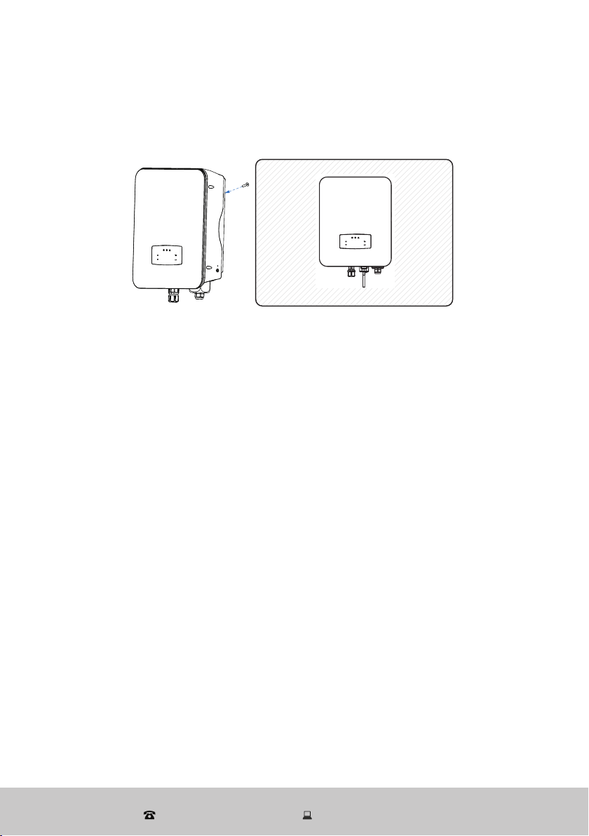
Installation 10
The inverter should be installed vertically on the wall, or lean back on plane
with a limited tilted angle. Please refer to below picture.
Leave the enough space around inverter, easy for accessing to the inverter,
connection points and maintenance.
<15°
>0°
Max
300mm
300mm 300mm
500mm
50mm
The inverter should be installed vertically on the wall, or lean back on a plane with a
limited tilted angle. Please refer to the below picture.

13
After Sales Support
1300 886 605 (AUS) | tempo.org/support
Installation (Cont.)
Installation 10
The inverter should be installed vertically on the wall, or lean back on plane
with a limited tilted angle. Please refer to below picture.
Leave the enough space around inverter, easy for accessing to the inverter,
connection points and maintenance.
<15°
>0°
Max
300mm
300mm 300mm
500mm
50mm
Leave the enough space around the inverter to allow for easy for access to the inverter
and its connection points for maintenance.
Mounting
Step 1:
264mm
219mm
17mm
Step 2:
14 After Sales Support
1300 886 605 (AUS) | tempo.org/support
Installation (Cont.)
Security
screw
Step 3:

15
After Sales Support
1300 886 605 (AUS) | tempo.org/support
Electrical Connection
Grid
Wind Turbines PV Array
Wind Turbines PV Array
Smart meter
TV
1234567 8
No. COM2
1
2
3
4
5
6
7
8
COM1
NTC+
NTC-
Dry Contact
Dry Contact
DRM
DRM
CTU
CTN
Meter 485A
Meter 485B
BAT 485A
485A
485B
BAT CANH
BAT CANL
BAT 485B
Communication Adapter pin assignment
Note:
• For diesel generators or multi-machine parallel use, please contact the
manufacturer, and provide installation and operation instructions separately.
Installation (Cont.)

16 After Sales Support
1300 886 605 (AUS) | tempo.org/support
PV Connection
This series of hybrid inverter has one/two MPPT channels, can be connected with
one/two strings of PV panels. Please make sure below requirements are followed
before connecting PV panels and strings to the inverter:
• The open-circuits voltage and short-circuit current of PV string should not exceed
the reasonable range of inverters.
• The isolation resistance between PV string and ground should exceed 300 kΩ.
• The polarity of PV strings are correct.
• Use the DC plugs in the accessory.
• The lightning protector should be equipped between PV string and inverter.
• Disconnect all of the PV (DC) switches during wiring.
WARNING!
The DC voltage may be fatally high - please comply with electrical safety warnings
when connecting. Please make sure the correct polarity of the cable is connected
with inverter, otherwise the inverter could be damaged.
Step 1:
Note: PV cable suggestion for cross section is 4 mm2.
Step 2:
MC
MC
!
Note: Please use PV connector crimper to pinch the point of the arrow.
Note: You’ll hear a click sound when the connector assembly is correct.
Installation (Cont.)

17
After Sales Support
1300 886 605 (AUS) | tempo.org/support
Step 3:
Battery Connection
These hybrid inverters are compatible with a lithium battery. For a lead acid battery or
batteries from other brands, please contact Tempo for technical support.
Note: BMS (Battery Management System) communication is needed between inverter
and battery.
Step 1:
Note: Battery cable suggestion Cross - section 8-10 AWG. Please make sure the
battery polarities are correct.
Battery cable
19±1mm
Installation (Cont.)

18 After Sales Support
1300 886 605 (AUS) | tempo.org/support
Step 2:
Pass the crimped battery harness through the waterproof connector and the cover.
Step 3:
Insert the wire harness into the terminals according to “+” and “-” polarity. Make sure
the the insulated terminals are parallel with the terminals. The crimping screw torque
should be 2.0±0.1N.m
Step 4:
A “click” sound will be heard when the connector assembly is correct.
Installation (Cont.)

19
After Sales Support
1300 886 605 (AUS) | tempo.org/support
Step 5:
Use an open-end wrench to tighten the waterproof lock.
Step 6:
Insert the battery connector into the inverter, if hear a “click”, it means the battery
connection is finished.
Installation (Cont.)

20 After Sales Support
1300 886 605 (AUS) | tempo.org/support
Installation (Cont.)
45
CAN/RS485
Lithium
PINA ssignment
1PIN2 3 678
5
1-3
4CANH
/
6-8
CANL
/
2345678
PIN Assignment
1PIN
4-5
1-2
3RS485A
/
6
/
7-8 /
RS485B
Lithium Battery Communication Connection
The inverter uses RS485 cable to communicate with the Meter and CAN to
communicate with the battery’s BMS. The image below shows the assembly of the
RS485/CAN communication cables.
Lead acid battery-NTC
The NTC cable enables the communication between the inverter and Lead acid
batteries.
Note:
1. NTC (including connection line) is provided by battery manufacturers.
2. The NTC is external, and there is no NTC connection port on
the lead-acid battery. NTC is used to test the working environment
temperature of lead-acid batteries.
NTC Cable
External NTC
3-8
1
2
PIN Assignment
NTC-
NTC+
RJ45 Plug
12345678
/
Lead Acid
This manual suits for next models
2
Table of contents


