VST VST300 User manual

Pure Sine Wave Inverter USER’S MANUAL
DC-AC Off-grid Single-phase Power Inverter
Special Feature:
with LCD display:Battery capacity rate,Battery voltage,AC voltage,AC power
Can be used to resistance, inductive and capacitive load,such as air conditioner,fridge,pump,
motor, electric welder, incandescent lamp, energy saving light...

2
Input & output fully isolation
Soft Start
Two multiple controlled DC fans: Temperature and Load:
Temperature>55°C±5°C,cooling fan start working
Temperature<50°C±5°C,cooling fan stop working
Load rate≥35% rated power, cooling fan start working
Load rate≤15% rated power, cooling fan stop working
Extensive electronic protection: Low voltage alarm, Low voltage cutoff, Over voltage, Over
temperature, AC Overload, AC Output short circuit, Reverse polarity
12V/24V/48Vdc input
110V/120V/220V/230/240Vac output
Pure sine wave output
Frequency:50Hz/60Hz
CE and RoHS Approved
24 months warranty
ODM/OEM available
Before using the inverter, you need to read and save the safety instructions.
Table of contents
1. Introduction…………………………………………………………………3
1.1 Brief Introduction………………………………………………………3
1.2 Features…………………………………………………………………3
1.3 Inverter Operation………………………………………………………3
2. Important Safety Instructions………………………………………………4
3. Functions……………………………………………………………………4
3.1 DC Input Panel…………………………………………………………4
3.2 AC Output Panel………………………………………………………5
4. How to use inverter…………………………………………………………8
4.1 Load consideration……………………………………………………8
4.2 Working time……………………………………………………………8
4.3 Battery wiring examples…………………………………………………9
5. Protection……………………………………………………………………9
6. Troubleshooting……………………………………………………………10
7. Specifications…………………………………………………………………11
8. Maintenance and Warranty…………………………………………………12
Appendix I: Manual/Automatic Turn Page…………………………………………13
Appendix II: Recommend…………………………………………………………14

3
The information presented in this document does not form part of any quotation or contract,
is believed to be accurate and reliable and may be changed without notice.
1. Introduction
1.1 Brief Introduction:
This product is a pure sine wave inverter which can convert 12/24/48Vdc to 110/230Vac 50/60Hz
based on full digital and intelligent design. It features high reliability, high efficiency, full
protection functions, easy installation and operation. The inverter can be applied in many fields,
such as household appliances, electric tools and industrial devices etc, especially for solar
photovoltaic power system.
1.2 Features:
LCD display for battery capacity, battery voltage, AC voltage, AC power
Complete isolation-type inverter technology
Continuous operation at full power
Wide DC input voltage range
Wide working temperature range
Low output harmonic distortion(THD≤3%)
Adoption of advanced SPWM technology, pure sine wave output
Extensive protections: Under/over input voltage, Short-circuit, Overload, Reverse polarity,
Over-temperature, and inverter’s inner fault identification protections.
1.3 Inverter Operation:
Connect the input and output terminals accurately. Turn on the power using the ON/OFF switch
on the front panel. In order to avoid the protections resulted from the surge power, please turn on
AC loads one by one after the output of the inverter is normal. Please check it as below:
Ensure that the ON/OFF switch on the Inverter is in the OFF position. If the power source is
a DC power supply, switch it OFF as well.

4
Connect inverter to power source.
Connect the DC cables to the DC battery terminals on the rear panel of the inverter. The red
terminal is positive (+) and the black terminal is negative (-).
Connect inverter to appliances. Make sure the load power within the rated power of inverter and
the start power should not exceed the peak power of the inverter. When having the inverter
connected with appliances and a power supply, switch on the inverter and appliances. If you are
operating several loads from the power inverter, turn them on separately after the inverter has
been turned on. This will ensure that the power inverter does not have to deliver the starting
currents for all the loads at once.
2. Important Safety Instructions
As an AC power supply equipment, the inverter’s output voltage is with the same level as that of
household power plug. Mind the AC output terminals, or you may get an electric shock and result
in life danger!
Attentions:
Do not attempt to connect the any other power source, including any AC power source.
Make sure the opening to the ventilation fan and vent holes are not blocked.
To avoid electrical hazard, be sure to unplug the inverter from its external power source
before inserting the AC plug.
For indoor use only. Avoid exposure to external heat sources; direct, prolonged sunlight; dust;
corrosive chemicals; and moisture.
It is normal for inverters to become warm during use. Avoid touching the device during use.
Avoid placing in direct sunlight or near heat-sensitive materials.
Always with the supplied cables and connectors as shown. Use of cables, connectors, or
accessories not supplied with this product constitutes misuse and may result in injury or
damage.
Keep the inverter out of children touch.
Avoid pulling on the cords and cables. Always grip plugs firmly when unplugging from
power source and when disconnecting cables.
Disconnect all AC and DC side connections before working on any circuits associated with
the inverter. Turning the ON/OFF switch on the inverter to off position may not entirely
remove dangerous voltage.

5
It’s an off-grid inverter, if connect to the grid, the inverter may be damaged.
This inverter can only be used singly, parallel connection or in series will damage it.
Do not attempt to repair the fault inverter yourself, otherwise it may lead to a serious
accident. Please contact the manufacture’s engineer.
3. Functions
This pure sine wave inverter have two versions: LCD display, LED Display
3.1 DC Input Panel
Intelligent Cooling Fan DC Input Terminal

6
Intelligent Cooling Fan DC Input Terminal
3.2 AC Output Panel
Vent Outlet AC Output Receptacle LED Display On/Off Switch

7
Vent Outlet AC Output Receptacle LED Display Power On/Off
Mode1/Mode2 Shift
PE/GND Vent Outlet AC Output Receptacle LED Display Power On/Off

8
PE/GND Vent Outlet AC Output Receptacle(Intelligent Cooling Fan 是标注
错误) LCD Display Power On/Off Mode1/Mode2 Shift
PE/GND AC-L AC-PE/GND Vent Outlet AC Output Receptacle
Overload Protection LCD Display Power On/Off Mode1/Mode2 Shift
P. S .:
※AC Output Receptacle:For application demands of different geographic
areas all over the world, there are many different kinds of optional AC

9
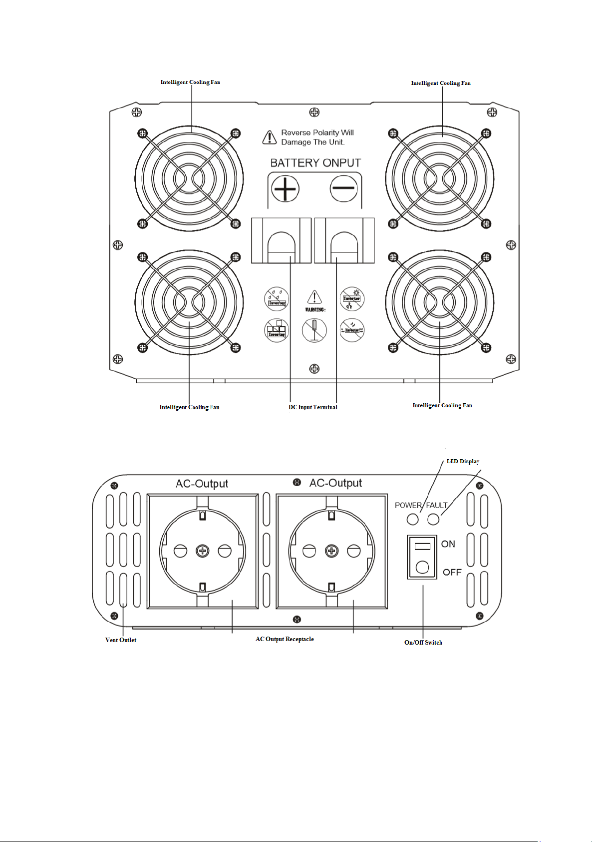
receptacle to choose from.
※Automatic/Manual turn page:
Mode1(Manual turn page):Press “Option”button one time, manual flip display
Mode2(Automatic turn page):Long press and hold for 5s,every 3s automatic display
※LCD display:Battery capacity, DC volt, AC volt, AC output power.
※Max current for AC output receptacle is 15A.
AC output receptacle over 15A(3300W),the “Overload protection” will be disconnected.
AC-L/AC-N terminal is used for high power electrical appliances.
4.How to use inverter
4.1 Load consideration:
When an appliance with a motor starts, it requires a momentary surge of power. This surge of
power is the “starting load” or “peak load”. Once started, the appliance requires less power to
continue to operate. This is known as the “continuous load”. It is important to know the starting
loads and the continuous loads of the appliances that are to be powered by the inverter.
Appliance power is rated in watts. This information is usually stamped or printed on most
appliances and equipment. In some cases, a tool will be rated in amperes. To convert from amps to
watts, multiply: Amps*AC voltage = Watts
This formula yields an approximation of the continuous wattage load of that appliance.
The startup load of an appliance is a major factor of whether this inverter can power it.
Startup load is momentary. With many appliances, it is approximately twice the continuous load,
but some appliance startup loads can be as high as eight times the continuous load.
To determine if an appliance or tool will operate with this inverter, run a test. This inverter will
automatically shut down in the event of an output overload, so there is no danger of damaging
either the inverter or the equipment.
4.2 Working time:
The battery working time in hours can be calculated using following formula:
Working hours(H)=Battery capacity(AH)*Battery volt(V)*0.8*0.9/Load in Watts
P.S: Because the battery can’t be fully discharged, usually 20% can’t discharge, so the maximum
power to multiply 0.8, This is the actual power of the battery can work, the inverter also has the
conversion efficiency, for pure sine in general efficiency about 90%, so here selected 0.9:
For example: a 12V/60Ah Battery, a 220v/100w filament lamp,
Working Time=12(V)*60(AH)*0.8*0.9/100(W)=5.18(Hour),
There are additional factors that determine actual run time. These include:
•AC appliance load and time in use (basic AH).
• Cable gauge and length (cable losses).
• Charge level of the batteries (between use, chargers have to be able to fully charge the batteries).

10
• Temperature of the batteries (colder batteries provide fewer amps).
• Age and condition of the batteries (older batteries lose AH capacity).
• Compliance with turning off unnecessary AC loads.
• Use of DC appliances and compliance with turning off unnecessary DC loads.
4.3 Battery Wiring Examples
In renewable energy systems, batteries are connected to each other in one of three ways:
•Series (voltage increases, amperage stays the same as a single battery)
•Parallel (voltage stays the same as a single battery, amperage increases)
•Series/Parallel (both voltage and amperage increase)
5.Protection
Inverter is equipped with numerous protection features to ensure safe operation.
Input Low Voltage Protection:
When input voltage is below 10V±4%(12V)/20V±4% (24V input)/40V±4% (48V), AC output
will be automatically shut off.
LED display:Buzzer sound 3 times and red light blinking.
LCD display:Buzzer sound 3 times, “AC-V” zero, “Battery Display” flashing in red.
Input Over Voltage Protection:
When input voltage reach 15.5V±4%(12V)/31V±4%(24V)/62V±4%(48V), AC output will

11
be shut off automatically.
LED display:Buzzer sound 4 times and red light blinking.
LCD display: Buzzer sound 4 times, “AC-V” zero.
Short Circuit Protection:
When short circuits occur, no damage to the unit, automatically recovery.
Overload Protection:
a.120%-145% rated power, Beep sound lasted about 10seconds and AC output shut off
b.Over 145% rated power, Beep sound lasted 2seconds and AC output shut off.
Reverse polarity protection: Fuse
When battery terminals are reverse connected, fuse will be burned to protect
Over Temperature Protection:
When inner temperature exceeds 75ºC, Buzzer sound 5 times, AC output will automatically
shut off.
6.Troubleshooting
SYMPTOM POSSIBLE CAUSE SOLUTIONS
ON/OFF switch is
switched on, LED
does not light,Buzzer
is off.,no AC voltage
There is no voltage at the DC
input Terminals
1.Check the continuity of the battery input
circuit
2.Check that the battery fuse is intact. Replace
if blown
3. Check that all connections in the battery
input circuit are tight
Polarity of the input voltage has
been reversed that has blown the
fuses.
Correct the polarity of the input connections
and replace the fuse. If the unit does not work
after replacing the f
use, the unit has been
permanently damaged.
Buzzer sound 1 time.
There is no AC
voltage.
1.AC output connections loose
2.Short-circuit of AC Output
wiring.
1.Tighten AC output connections
2.Check AC wiring for short circuit.
Buzzer sound 3times
DC input volt lower than
10V±4% (12V version)
20V±4% (24V version)
40V±4%(48Vversion)
1.Check that the battery is fully charged.
Recharge, if low.
2.Check that the battery cables are thick enough
to carry the required
current over the required
length. Use thicker cables, if required
3.Tighten connections of the battery input
circuit.
Buzzer sound 4 times Higher input DC volt than
15.5V±4% (12V version),
31V±4%(24V version),
62V±4% (48V version)
1.Check that the voltage at the DC input
terminals is more than 15.5V/31V/62V DC.
2.Ensure that the max charging voltage of the
battery charger/alternator/solar charge
controller is below 15.5V/31V/62VDC
3.Ensure that an un-regulated solar panel or
wind turbine is not used to charge a battery
System overheating
1.Check that the fan is working. If not, the fan /

12
Buzzer sound 5 times
fan control circuit may be defective.
2.If the fan is working, check that the
ventilation slots on the suction
side and the
openings on the discharge side of the fan are
not obstructed
3.Reduce the load to reduce the heating effect
4.After the cause of overheating is removed and
the unit cools down, it will reset automatically
1.B
eep sound lasted
10s
2.Beep sound lasted 2s
Over-load protection
1.Disconnect the load
2.Reduce the load
3.Cool the unit.
7.Specifications
Item Model
VST300 VST500 VST600 VST1000 VST1200 VST1500
O
U
T
P
U
T
Rated Power 300W 500W 600W 1000W 1200W 1500W
Peak Power 600W 1000W 1200W 2000W 2400W 3000W
AC Voltage
100V/110V/115V/120Vac or 220V/230V/240Vac
AC output regulation:±3.0%
Frequency:50Hz±0.5Hz,60Hz±0.5Hz
Waveform Pure Sine Wave(THD<3%) at rated input voltage
Protection AC short circuit, Overload, Over temperature
I
N
P
U
T
Bat. Voltage Range 11V-15.5V(12V version) 22V-31V(24V version) 44V-62V(48V version)
Efficiency More than 90%
Protection Battery Low Alarm, Battery Low Shutdown, Battery Polarity Reverse by Fuse
Battery Types Open & sealed lead acid battery
Dimension((L*W*H)cm 26*13*5.326*13*5.3 21*15*7 33*18*7 33*18*7 37*18*7
Packing
PCS/CTN 12 12 12 4 4 4
KGS/CTN(KGS) 13.5.5 16.5 16.5 12.5 12.5 15
MEAS(L*W*H)cm 56*37*3156*37*3156*37*31 46*40*24.5 46*40*24.5 47*46*24.5
Item Model
VST2000 VST2500 VST3000 VST4000 VST5000 VST6000
O
U
T
P
U
T
Rated Power 2000W 2500W 3000W 4000W 5000W 6000W
Peak Power 4000W 5000W 6000W 8000W 10000W 12000W
AC Voltage
100V/110V/115V/120Vac or 220V/230V/240Vac
AC output regulation:±3.0%
Frequency:50Hz±0.5Hz,60Hz±0.5Hz
Waveform Pure Sine Wave(THD<3%) at rated input voltage
Protection AC short circuit, Overload, Over temperature
I
N
P
Bat. Voltage Range 11V-15.5V(12V version) 22V-31V(24V version) 44V-62V(48V version)
Efficiency More than 90%
Protection Battery Low Alarm, Battery Low Shutdown, Battery Polarity Reverse by Fuse

13
U
T
Battery Types Open & sealed lead acid battery
Dimension((L*W*H)cm 38*22*9 38*22*9
48*22*9.2 45*22*15.5 48*22*15.5 48*22*15.5
Packing
PCS/CTN
2
2 2 111
KGS/CTN(KGS) 12 12 16 10 11 12
MEAS(L*W*H)cm 44*30*38.5 44*30*38.5 53*30*38.5 55*29*25 55*29*25 55*29*25
AC Out Receptacle USA, UK, Germany, France, Australia, Brazil, Italy, South Africa, Japan,etc.
Cooling Temperature and Load Controlled
Environment
Operating Temp. -15 ° C to 40° C
Storage Temp. -30° C to 70°C
Relative Humidity 20% ~ 90% RH non-condensing
Note: The specifications are subject to change without prior notice for further improvement of
products.
8. Maintenance and Warranty
The casing of the inverters may be cleaned regularly with a damp cloth (not wet) to prevent
accumulation of dust and dirt. The screws on the DC input terminals must be tightened.
The warranty period of the inverter is 2 year since the date of original shipping. Within the period,
we will repair the product or replace the defective product for free. Return the defective with
shipping cost prepaid. And provide proof of purchasing date. We will pay the return shipping
charges within warranty period. The warranty doesn’t apply under the following conditions:
1. Damaged by accident, negligence, abuse, improper use
2. Input voltage exceed the nominal input voltage of inverter
3. Unauthorized modification or attempted repair

14
Appendix I:Manual/Automatic Turn Page
Mode1----Manual Turn Page
Press “Option” Button
1)Display Battery Capacity rate
2)Display AC Voltage
3)Light over “AC-V” lighting
4)Light over “Mode1” lighting
Status display:Battery capacity(%),AC Voltage
One Touch “Option” Button
1)Display Battery Capacity rate
2)Display AC Output Power
3)Light over “AC-W” lighting
4)Light over “Mode1” lighting
Status display:Battery capacity(%),AC Output Power(Loads power)

15
Touch again“Option” Button
1)Display Battery Capacity rate
2)Display DC Voltage
3)Light over “DC-V” lighting
4)Light over “Mode1” lighting
Status display:Battery capacity(%),DC Voltage
Mode2----Automatic Turn Page
Mode2:Automatic Turn Page
Long press “Option” Button and hold 5s
1)Long press “Option” Button and hold for 5s until “Mode2” lighting then release
2)Every 3s will display one status
3)Display in turn:AC Voltage,AC Output Power,DC Voltage,Battery Capacity Rate(%)
Appendix II:Recommend
For correct operation, the battery voltage should be between 0.9xVnom and 1.29xVnom where
Vnom is 12V,/24V/48V depending on model, and must be able to supply sufficient current to
inverter. The following table displays the recommended (battery cable, Fuse, Battery Capacity)
per inverter type :
Inverter type Input Voltage DC Battery Cable Fuse Battery Capacity
300W
12V 4
mm²
(1*Red/1*Black) 40A*1 ≥50Ah
24V 2.5
mm²
(1*Red/1*Black) 20A*1 ≥25Ah
48V 2.5mm² (1*Red/1*Black) 10A*1 ≥12Ah
500W/600W
12V 6mm² (1*Red/1*Black) 40A*2 ≥100Ah
24V 4mm² (1*Red/1*Black) 40A*2 ≥50Ah
48V 2.5mm² (1*Red/1*Black) 10A*2 ≥25Ah
1000W
12V 10mm² (1*Red/1*Black) 40A*4 ≥160 Ah
24V 6mm² (1*Red/1*Black) 20A*4 ≥80Ah
48V 4
mm²
(1*Red/1*Black) 10A*4 ≥40Ah
1500W
12V 10
mm²
(2*Red/2*Black) 40A*6 ≥250Ah
24V 6
mm²
(2*Red/2*Black) 20A*6 ≥125Ah
48V 4
mm²
(2*Red/2*Black) 10A*6 ≥60Ah

16
2000W
12V 16mm² (2*Red/2*Black) 40A*8 ≥320Ah
24V 10mm² (2*Red/2*Black) 20A*8 ≥160Ah
48V 6mm² (2*Red/2*Black) 10A*8 ≥80Ah
2500W
12V 16mm² (2*Red/2*Black) 40A*8 ≥400Ah
24V10
mm²
(2*Red/2*Black) 20A*8 ≥200Ah
48V 6
mm²
(2*Red/2*Black) 10A*8 ≥100Ah
3000W
12V 16
mm²
(2*Red/2*Black) 40A*12 ≥480Ah
24V 10
mm²
(2*Red/2*Black) 20A*12 ≥240Ah
48V 6
mm²
(2*Red/2*Black) 10A*12 ≥120Ah
4000W
12V 25mm² (2*Red/2*Black) 40A*12 ≥640Ah
24V 16mm² (2*Red/2*Black) 20A*12 ≥320Ah
48V 10mm² (2*Red/2*Black) 10A*12 ≥160Ah
5000W
12V 35mm² (2*Red/2*Black) 40A*20 ≥800Ah
24V 25mm² (2*Red/2*Black) 20A*20 ≥400Ah
48V 16mm² (2*Red/2*Black) 10A*20 ≥200Ah
6000W
12V
35
mm²
(2*Red/2*Black) 40A*20 ≥960Ah
24V
25
mm²
(2*Red/2*Black) 20A*20 ≥480Ah
48V
16
mm²
(2*Red/2*Black) 10A*20 ≥240Ah
Version No. : V1.0
This manual suits for next models
11
Table of contents
Popular Inverter manuals by other brands

SCS Sentinel
SCS Sentinel SolarGate AAM0095 quick start guide

SOLARA
SOLARA M Series installation manual

Stanford Research Systems
Stanford Research Systems DS360 Operating manual and programming reference

Cobra
Cobra IG32ESI user manual

gefran
gefran SIEIDrive ADL300 Safety user manual

Toshiba
Toshiba TOSVERT VF-AS3 instruction manual