Grundfos RSI User manual

RSI, 1.5-250 kW (2-350 hp)
Installation and operating instructions
RSI
Installation and operating instructions
(all available languages)
http://net.grundfos.com/qr/i/98464145
RSI, advanced
Installation and operating instructions
(all available languages)
http://net.grundfos.com/qr/i/99116147
GRUNDFOS INSTRUCTIONS


RSI, 1.5-250 kW (2-350 hp)
English (GB)
Installation and operating instructions ..................................4
Español (ES)
Instrucciones de instalación y funcionamiento............................36
Français (FR)
Notice d'installation et de fonctionnement...............................69
Português (PT)
Instruções de instalação e funcionamento .............................102
3
Table of contents

English (GB) Installation and operating instructions
Original installation and operating instructions
Table of contents
1. General information ............. 4
1.1 Hazard statements .............. 4
1.2 Notes ..................... 4
2. Receiving the product............ 5
3. Technical data ................ 6
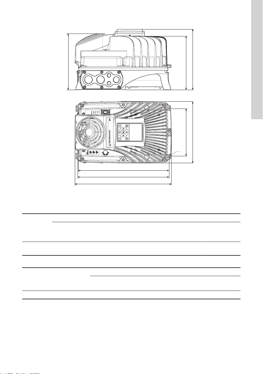
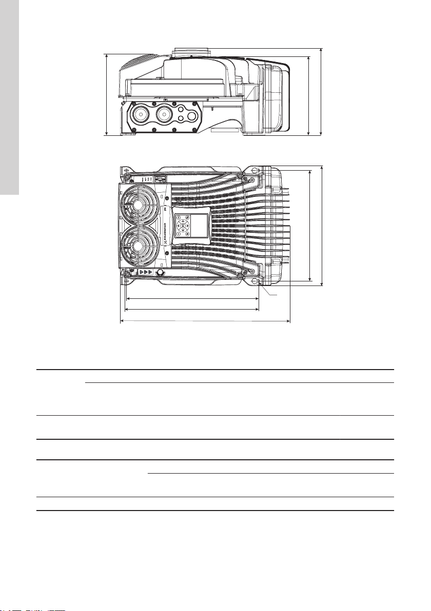
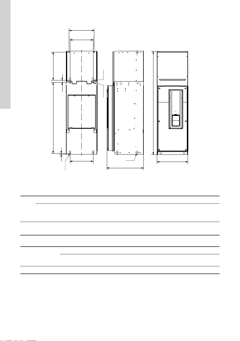
3.1 Product range ................. 6
3.2 Technical data.................13
4. Installing the product ............17
4.1 Installation example..............18
4.2 Electrical connection .............19
5. Operation...................23
5.1 Operating panel ................24
5.2 Startup wizard parameter description ....25
6. Fault finding the product ..........26
6.1 Fault codes and remedies ..........26
6.2 Resetting fault codes .............33
6.3 Fault history ..................33
6.4 Reset to factory default ............33
7. Servicing the product ............33
7.1 Routine inspection ..............33
7.2 Inspection and replacement of wear parts..35
7.3 Storage and warranty .............35
8. Disposing of the product ..........35
1. General information
Read this document before you install the
product. Installation and operation must
comply with local regulations and accepted
codes of good practice.
1.1 Hazard statements
The symbols and hazard statements below may
appear in Grundfos installation and operating
instructions, safety instructions and service
instructions.
DANGER
Indicates a hazardous situation which, if
not avoided, will result in death or serious
personal injury.
WARNING
Indicates a hazardous situation which, if
not avoided, could result in death or seri-
ous personal injury.
CAUTION
Indicates a hazardous situation which, if
not avoided, could result in minor or mod-
erate personal injury.
The hazard statements are structured in the following
way:
SIGNAL WORD
Description of the hazard
Consequence of ignoring the warning
• Action to avoid the hazard.
1.2 Notes
The symbols and notes below may appear in
Grundfos installation and operating instructions,
safety instructions and service instructions.
Observe these instructions for explosion-
proof products.
A blue or grey circle with a white graphical
symbol indicates that an action must be
taken.
A red or grey circle with a diagonal bar,
possibly with a black graphical symbol, in-
dicates that an action must not be taken or
must be stopped.
If these instructions are not observed, it
may result in malfunction or damage to the
equipment.
Tips and advice that make the work easier.
4
English (GB)

2. Receiving the product
Check the condition of the inverter before
installation. Do not install the inverter if the
equipment appears to be damaged.
In case of any deviation from the order, contact
Grundfos immediately. Once you get the product,
perform the following inspections before installation:
• Make sure the product corresponds to the order.
• Check for any visual damage or scratch.
• Make sure the list of components and accessories
is complete.
• Make sure that the fastening parts are tightened
properly.
5
English (GB)

3. Technical data
3.1 Product range
3.1.1 Dimensions
E
W
W2
L1
L
L2
H
H2
H1
TM066526
Frame A 1.5 - 5.5 kW (2 - 7.5 hp)
Frame size
Product
Net weight
[kg (lbs)]
E
[mm
(in)]
W
[mm
(in)]
W2
[mm
(in)]
L
[mm
(in)]
L1
[mm
(in)]
L2
[mm
(in)]
H
[mm
(in)]
H1
[mm
(in)]
H2
[mm
(in)]
Frame A 8.8 (19) ∅5.9
(0.23)
143.5
(5.7)
191
(7.5)
297
(11.7)
293
(11.5)
315
(12.4)
188
(7.4)
197
(7.8)
214
(8.4)
Frame size
Package
Gross weight
[kg (lbs)]
Length
[mm (in)]
Width
[mm (in)]
Height
[mm (in)]
Frame A 310 (683) 250 (9.8) 200 (7.9) 295 (11.6)
6
English (GB)

E
W
W2
H
H2
H1
L1
L
L2
TM066527
Frame B 7.5 - 15 kW (10-20 hp)
Frame size
Product
Net weight
[kg (lbs)]
E
[mm
(in)]
W
[mm
(in)]
W2
[mm
(in)]
L
[mm
(in)]
L1
[mm
(in)]
L2
[mm
(in)]
H
[mm
(in)]
H1
[mm
(in)]
H2
[mm
(in)]
Frame B 15 (33) ∅6.1
(0.24)
180
(7.1)
233
(9.2)
349
(13.7)
345.2
(13.6)
368
(14.5)
204
(8.0)
214
(8.4)
231
(9.1)
Frame size
Package
Gross weight
[kg (lbs)]
Length
[mm (in)]
Width
[mm (in)]
Height
[mm (in)]
Frame B 310 (683) 250 (9.8) 200 (7.9) 295 (11.6)
7
English (GB)

E
W
W2
H
H2
H1
L1
L
L2
TM066528
Frame C 18.5 - 37 kW (25-50 hp)
Frame size
Product
Net weight
[kg (lbs)]
E
[mm
(in)]
W
[mm
(in)]
W2
[mm
(in)]
L
[mm
(in)]
L1
[mm
(in)]
L2
[mm
(in)]
H
[mm
(in)]
H1
[mm
(in)]
H2
[mm
(in)]
Frame C 32 (69) ∅8.2
(0.32)
322
(12.7)
350
(13.8)
385
(15.2)
382.5
(15.1)
500
(19.7)
230
(9.1)
236
(9.3) 254 (10)
Frame size
Package
Gross weight
[kg (lbs)]
Length
[mm (in)]
Width
[mm (in)]
Height
[mm (in)]
Frame C 310 (683) 250 (9.8) 200 (7.9) 295 (11.6)
8
English (GB)

259
237
660
645
190
190
Ø16
Ø9
Ø20
TM075444
Frame MR7 45-55 kW (60-74 hp)
Frame
size
Product
Net
weight
[kg (lb)]
E
[mm (in)]
E1
[mm (in)]
E2
[mm (in)]
W
[mm (in)]
W2
[mm (in)]
L
[mm (in)]
L2
[mm (in)]
H2
[mm (in)]
Frame
MR7
37.5
(82.67)
∅9
(0.35)
∅16
(0.63)
∅20
(0.79)
190
(7.48)
237
(9.33)
645
(25.39)
660
(25.98)
259
(10.20)
Frame size
Package
Gross weight
[kg (lb)] Length [mm (in)] Width [mm (in)] Height [mm (in)]
Frame MR7 40.5 (89.29) 320 (12.60) 330 (12.99) 750 (29.53)
9
English (GB)

235
262
663
216
22
9
996
343
217 290
Ø9
Ø11 Ø9
Ø22
TM075445
Frame MR8 110 kW (148 hp)
Frame
size
Product
Net
weight
[kg (lb)]
E
[mm
(in)]
E1
[mm
(in)]
E2
[mm
(in)]
W
[mm
(in)]
W1
[mm
(in)]
W2
[mm
(in)]
W3
[mm
(in)]
L
[mm
(in)]
L2
[mm
(in)]
L3
[mm
(in)]
H2
[mm
(in)]
Frame
MR8
66
(145.50)
∅9
(0.35)
∅11
(0.43)
∅22
(0.87)
217
(8.54)
216
(8.50)
290
(11.42)
235
(9.25)
663
(26.10)
996
(39.21)
262
(10.31)
343
(13.50)
Frame size
Package
Gross weight [kg
(lb)] Length [mm (in)] Width [mm (in)] Height [mm (in)]
Frame MR8 80.5 (177.47) 540 (21.26) 430 (16.93) 1140 (44.88)
10
English (GB)

810 27.5 284
365
355
292
400
480
360
14
1122
1150
Ø22
360
Ø9
Ø9
M8 GND
Ø9
Ø9
TM075446
Frame MR9 132- 160 kW (177-215 hp)
Frame
size
Product
Net
weight
[kg
(lb)]
E
[mm
(in)]
E1
[mm
(in)]
W
[mm
(in)]
W1
[mm
(in)]
W2
[mm
(in)]
L
[mm
(in)]
L1
[mm
(in)]
L2
[mm
(in)]
L3
[mm
(in)]
H
[mm
(in)]
H1
[mm
(in)]
H2
[mm
(in)]
Frame
MR9
119.50
(263.45
)
∅9
(0.35)
∅22
(0.87)
400
(15.75)
360
(14.17)
480
(18.90)
1122
(44.17)
810
(31.89)
1150
(45.28)
284
(11.18)
355
(13.98)
292
(11.50)
365
(14.37)
Frame size
Package
Gross weight
[kg (lb)]
Length
[mm (in)]
Width
[mm (in)]
Height
[mm (in)]
Frame MR9 148.00
(326.28)
570
(22.44)
730
(28.74)
1300
(51.18)
11
English (GB)

Ø13
Ø13
639
120.5
2200.5
2235.5
2255.5
555
Ø13
200
600
604
535
100
599
606
TM075727
Frame ED 200-250 kW (268-335 hp)
Frame
size
Product
Net weight
[kg (lb)]
E
[mm
(in)]
W
[mm
(in)]
W1
[mm
(in)]
W2
[mm
(in)]
L
[mm
(in)]
L1
[mm
(in)]
L2
[mm
(in)]
H
[mm
(in)]
H1
[mm
(in)]
H2
[mm
(in)]
Frame
ED
200 kW: 280
(617.29)
250 kW: 420
(925.94)
∅13
(0.51)
535
(21.06)
599
(23.58)
606
(23.86)
2235.5
(88.01)
2200.5
(86.63)
2255.5
(88.80)
600
(23.62)
604
(23.78)
639
(25.16)
Frame size
Package
Gross weight
[kg (lb)]
Length
[mm (in)]
Width
[mm (in)]
Height
[mm (in)]
Frame ED 200 kW: 351 (773.82)
250 kW: 491 (1082.47)
880
(34.65)
800
(31.50)
200 kW: 1300 (51.18)
250 kW: 2450 (96.46)
12
English (GB)

3.2 Technical data
Voltage 3 × 208-240 V 3 × 380-440 V
Installation environ-
ment
Minimum ambient temperature [°C (°F)] -10 (14) -10 (14)
Maximum ambient temperature [°C (°F)] 60 (140) 60 (140)
Maximum relative humidity [%] 100 100
Electrical data
Minimum MPP voltage [VDC] 230 450
Recommended MPP voltage [VDC] 290-336 530-615
Maximum input voltage [VDC] 400 800
Input voltage [VAC] 208-240 380-480
Rated output voltage [VAC] 208-240 380-440
Minimum frequency [Hz] 5 5
Maximum frequency [Hz] 160 160
Phases 3 3
Enclosure class IP66 IP54, IP66
13
English (GB)

3.2.1 Low voltage range (3 × 208-240 V)
Power
[kW (hp)] Product number
Electrical data
Frame size
Max. P2
[kW (hp)]
Rated output current
[A]
1.5 (2) 99090622 1.5 (2) 8 A
2.2 (3) 99090633 2.2 (3) 11 A
3.0 (4) 99090634 3.0 (4) 12.5 A
4.0 (5) 99090635 4.0 (5) 18 B
5.5 (7.5) 99090636 5.5 (7.5) 24.2 B
7.5 (10) 99090637 7.5 (10) 31 B
11 (15) 99090638 11 (15) 48 C
15 (20) 99090639 15 (20) 62 C
3.2.2 High voltage range (3 × 380-440 V)
Power
[kW] Product number
Electrical data
Frame size
Max. P2
[kW (hp)]
Rated output current
[A]
2.2 (3) 99044348 2.2 (3) 5.6 A
3.0 (4) 99044349 3.0 (4) 8 A
4.0 (5) 99044350 4.0 (5) 9.6 A
5.5 (7.5) 99044351 5.5 (7.5) 12 A
7.5 (10) 99044352 7.5 (10) 16 B
11 (15) 99044363 11 (15) 23 B
15 (20) 99044364 15 (20) 31 B
18.5 (25) 99044365 18.5 (25) 38 C
22 (30) 99044366 22 (30) 46 C
30 (40) 99044367 30 (40) 61 C
37 (50) 99044368 37 (50) 72 C
45 (60) 99648886 45 (60) 87 MR7
55 (74) 99648887 55 (74) 105 MR7
110 (148) 99648888 110 (148) 205 MR8
132 (177) 99648889 132 (177) 261 MR9
160 (215) 99648890 160 (215) 310 MR9
200 (268) 99648891 200 (268) 385 ED
250 (335) 99648892 250 (335) 460 ED
14
English (GB)

3.2.3 Drive efficiency (CDM)
The IE classification of the complete drive module (CDM) is based on the drive losses. The loss determination is
based on factory settings such as the default switching frequency. The efficiency of RSI is determined as
efficiency class IE2 according to EN 50598-2 and IEC 61800-9.
B [%]
A [%]
TM079993
Different operating points of RSI depending on the relative torque-producing current and the relative motor
stator frequency
Pos. Description
A Relative torque-producing current
B Relative motor stator frequency
Efficiencies and standby losses of RSI at different operating points
Drive efficiencies for low voltage range (3 × 208-240 V), IP66 variant
Variant,
power
[kW (hp)]
Apparent
power
[kVA]
Nominal
current
[A]
Standby
losses
[W]
Frequency[%]
10 10 10 50 50 50 90 90 90 100 100 100
Current [%]
25 50 100 25 50 100 25 50 100 25 50 100
Operating point
1 2 3 4 5 6 7 8 9 10 11 12
Relative losses [%]
1.5 (2) 3.2 8 14 1.89 2.10 2.61 1.94 2.23 2.93 2.00 2.43 3.46 2.01 2.46 3.58
2.2 (3) 4.4 11 14 1.62 1.86 2.42 1.69 2.01 2.81 1.74 2.24 3.49 1.76 2.29 3.66
3.0 (4) 5.0 12.5 14 1.55 1.79 2.39 1.61 1.95 2.81 1.65 2.21 3.56 1.67 2.27 3.74
4.0 (5) 7.2 18 14 1.36 1.57 2.06 1.42 1.69 2.34 1.47 1.85 2.76 1.48 1.90 2.87
5.5 (7.5) 9.6 24.2 14 1.04 1.29 2.00 1.10 1.42 2.35 1.14 1.61 2.93 1.15 1.65 3.07
7.5 (10) 12.3 31 14 0.97 1.23 1.99 1.03 1.37 2.40 1.07 1.59 3.10 1.09 1.64 3.27
11 (15) 19.1 48 18 1.07 1.32 2.04 1.13 1.46 2.42 1.18 1.65 3.04 1.19 1.70 3.19
15 (20) 24.7 62 18 0.99 1.26 2.03 1.06 1.41 2.47 1.11 1.64 3.23 1.12 1.69 3.42
15
English (GB)

Drive efficiencies for high voltage range (3 × 380-440 V), IP21, IP54, and IP66 variants
Variant,
power
[kW (hp)]
Apparent
power
[kVA]
Nominal
current
[A]
Standby
losses
[W]
Frequency[%]
10 10 10 50 50 50 90 90 90 100 100 100
Current [%]
25 50 100 25 50 100 25 50 100 25 50 100
Operating point
1 2 3 4 5 6 7 8 9 10 11 12
Relative losses [%]
2.2 (3) 3.9 5.6 14 1.46 1.61 1.93 1.50 1.67 2.08 1.52 1.76 2.32 1.52 1.77 2.38
3 (4) 5.5 8.0 14 1.21 1.35 1.70 1.24 1.43 1.88 1.27 1.54 2.19 1.28 1.56 2.26
4 (5) 6.7 9.6 14 1.11 1.26 1.63 1.15 1.35 1.83 1.17 1.47 2.18 1.17 1.51 2.27
5.5 (7.5) 8.3 12 14 0.88 1.05 1.58 0.91 1.14 1.84 0.94 1.28 2.31 0.95 1.32 2.43
7.5 (10) 11.1 16 14 0.79 0.95 1.42 0.82 1.03 1.61 0.85 1.13 1.92 0.86 1.15 2.00
11 (15) 15.9 23 14 0.70 0.87 1.38 0.73 0.95 1.62 0.75 1.08 2.02 0.76 1.11 2.11
15 (20) 21.5 31 14 0.68 0.87 1.41 0.72 0.95 1.64 0.74 1.08 2.04 0.75 1.11 2.14
18.5 (25) 26.3 38 18 0.79 0.97 1.51 0.82 1.05 1.74 0.85 1.18 2.14 0.85 1.20 2.23
22 (30) 31.9 46 18 0.77 0.95 1.48 0.80 1.03 1.68 0.82 1.14 2.03 0.83 1.16 2.11
30 (40) 42.3 61 18 0.71 0.90 1.46 0.75 0.99 1.70 0.77 1.12 2.13 0.78 1.15 2.24
37 (50) 49.9 72 18 0.69 0.89 1.47 0.72 0.98 1.74 0.75 1.12 2.24 0.76 1.16 2.36
45 (60) 60.3 87 31 0.57 0.76 1.36 0.60 0.83 1.54 0.63 0.93 1.79 0.63 0.95 1.86
55 (74) 72.7 105 31 0.55 0.76 1.41 0.59 0.84 1.61 0.62 0.94 1.90 0.62 0.96 1.97
110 (148) 142.0 205 46 0.51 0.71 1.39 0.55 0.79 1.57 0.57 0.88 1.85 0.58 0.90 1.92
132 (177) 180.8 261 45 0.59 0.79 1.43 0.63 0.86 1.60 0.65 0.95 1.84 0.66 0.97 1.90
160 (215) 214.8 310 45 0.57 0.79 1.50 0.61 0.86 1.68 0.64 0.96 1.95 0.64 0.98 2.01
200 (268) 266.7 385 45 0.44 0.63 1.27 0.47 0.70 1.44 0.50 0.80 1.72 0.50 0.82 1.79
250 (335) 318.7 460 90 0.51 0.68 1.19 0.55 0.76 1.37 0.58 0.85 1.61 0.58 0.87 1.66
16
English (GB)

4. Installing the product
DANGER
Death or serious personal injury
‐Before installation, make sure that the
power supply is switched off and it can-
not be switched on unintentionally.
WARNING
Death or serious personal injury
‐Installation must be carried out by
qualified staff.
WARNING
Death or serious personal injury
‐Use appropriate tools and safety
equipment when handling the product.
CAUTION
Minor or moderate personal injury
‐Use a proper lifting method when nec-
essary.
Electro-magnetic compatibility (EMC)
The drive must comply with the standard IEC
61000-3-12. The short-circuit power SSC must be a
minimum of 120 RSCE at the interface point between
your and the public mains. Make sure to connect the
drive and the motor to the mains with a short-circuit
power SSC that is a minimum of 120 RSCE. If
necessary, contact your mains operator.
Using an RCD or an RCM device
The drive can cause a current in the protective
grounding conductor. Use a residual current-operated
protective (RCD) device, or a residual current-
operated monitoring (RCM) device to give protection
against a direct or an indirect contact. Use a type B
RCD or RCM device on the mains side of the drive.
Adjust the minimum frequency to a value
that ensures water is discharged from the
outlet of the pump.
To adjust the minimum frequency, click the
Home button on the control panel and se-
lect minimum frequency.
To ensure a proper convective cooling ef-
fect, install the RSI according to fig. Instal-
lation example showing the required clear-
ance when mounting the product.
Do not install the equipment in direct sun-
light.
CAUTION
Minor or moderate personal injury
‐Ensure that the mounting wall can sup-
port the weight of the inverter. See the
weight in 3.2 Technical data.
Related information
3.2 Technical data
4.1 Installation example
17
English (GB)

4.1 Installation example
A
C B
A
T
TM078707
Installation example showing the required clearance when mounting the product
Min. clearance [mm]
Type A B C
All types 80 160 60
A = Clearance left and right from the drive
B = Clearance above the drive
C = Clearance underneath the AC drive drive
18
English (GB)

4.2 Electrical connection
WARNING
Death or serious personal injury
‐To avoid the risk of electric shock or
fire, make sure that the power supply
has been switched off before connect-
ing the equipment, and make sure the
earth terminal is reliably grounded.
WARNING
Death or serious personal injury
‐Make sure that reinforced protective
ground connection is present. It is
mandatory because the touch current
of the AC drives is more than 3.5 mA
AC (refer to EN 61800-5-1).
WARNING
Death or serious personal injury
‐Install the electrical connections ac-
cording to the wiring diagrams.
WARNING
Death or serious personal injury
‐The drive must always be grounded
with a grounding conductor that is con-
nected to the grounding terminal. The
terminal is identified with the grounding
symbol in 4.2.2 RSI input terminals.
To avoid arc discharge and fire, tighten all
terminals with the specified torque.
For distances (pump to the inverter) ex-
ceeding 15 m (50 ft), use a sine-wave filter
with matching current ratings.
Minimum cross-sectional area of protective
conductors (HD 60364-5-54)
Cross-sectional area of
the phase conductors
(S) [mm2]
The minimum cross-
sectional area of the
protective grounding
conductor [mm2]
S ≤ 16 S
16 < S ≤ 35 16
35 < S S/2
The values of the table are valid only if the protective
earthing conductor is made of the same metal as the
phase conductors. Otherwise the cross-sectional area
of the protective earthing conductor must be
determined in a manner that produces a conductance
equivalent to that which results from the application of
this table.
The cross-sectional area of each protective grounding
conductor that is not a part of the mains cable or the
cable enclosure, must be a minimum of 2.5 mm2 if
there is mechanical protection, and 4 mm2 if there is
not mechanical protection. If you have cord-
connected equipment, make sure that the protective
grounding conductor in the cord is the last conductor
to be interrupted, if the strain-relief mechanism
breaks.
Make sure to comply with the local regulations on the
minimum size of the protective grounding conductor.
19
English (GB)

4.2.1 Output filters
Output filters are used for reducing the voltage stress
on the motor windings and the motor insulation
system as well as for decreasing acoustic noise from
the motor driven by a frequency converter.
One type of output filter is available as an accessory
for the RSI:
• sine-wave filters.
Using of output filters
The table below shows when an output filter is
required and the type to use. The selection depends
on the following:
• pump type
• power cable length
• the required reduction of the acoustic noise from
the motor.
Pump type Shaft power, P2 Sine-wave filter
SP with motor voltage from 380 V All 0-300 m *
Pumps with MG71 and MG80 up to 1.5 kW (2 hp) Greater than 1.5 kW 0-300 m *
Reduction of noise emission, low reduction All -
Reduction of voltage peaks and noise emission, high reduction All 0-300 m *
* The lengths stated apply to the power cable.
20
English (GB)
Other manuals for RSI
5
Table of contents
Other Grundfos Inverter manuals

Grundfos
Grundfos RSI Operating manual

Grundfos
Grundfos RSI User manual

Grundfos
Grundfos CUE Operating manual

Grundfos
Grundfos RSI Series User manual

Grundfos
Grundfos RSI Installation and operation manual

Grundfos
Grundfos RSI User manual

Grundfos
Grundfos Solar 15-80 130 Owner's manual

Grundfos
Grundfos CUE User manual
Popular Inverter manuals by other brands

Universal Motors
Universal Motors UMA1 Series Operation manual

Hensel
Hensel TRIA 3000 AS user manual

Afore
Afore Residential HNS Series Installation and operation manual

V-TAC
V-TAC VT-6607105 instruction manual

Omnik New Energy
Omnik New Energy Omniksol-3k-TL2 user manual

Westerbeke
Westerbeke BCG 4.0 specification