Volt Polska sinusPRO E User manual

PRODUCT MANUAL
PURE SINE WAVE ELECTRONIC INVERTERS
WITH UPS
sinusPRO E
VOLT POLSKA Sp. z o.o.
ul. Grunwaldzka 76
81-771 Sopot
www.voltpolska.pl
WARRANTY CARD
FILL IN IF NEEDEED
(*) Cross incorrect
I agree to pay the cost of inverter repair due to:
* expiration of the warranty period / * warranty void
Before proceeding with the repair, service will inform by phone about the exact costs of the repair.
Please attach a copy of the purchase document (receipt or invoice) to the complaint.
The full regulations of service repairs can be found on our website www.voltpolska.pl
[email protected] (58) 341-05-06 | [email protected] (58) 341-38-80 | [email protected] (22) 100-42-99 [email protected] (58) 341-05-06 | [email protected] (58) 341-38-80 | [email protected] (22) 100-42-99 1
9
DATE OF PURCHASE
SHIPPING ADDRESS
SIGNATURE / STAMP
DAMAGE DESCRIPTION
SERVICE COMMENTS

Thank you for purchasing UPS from sinusPRO E series. Please read this user
manual before starting the device.
Inverter characteristics
źOne device with built-in DC / AC converter, an uninterruptible power supply unit and an automatic battery
charger
źToroidal transformer used in the converter ensures high efficiency and low idling current. The device is
much more energy-efficient than older constructions that used E-type transformers
źFast 32-bit microprocessor ensures accurate and trouble-free operation
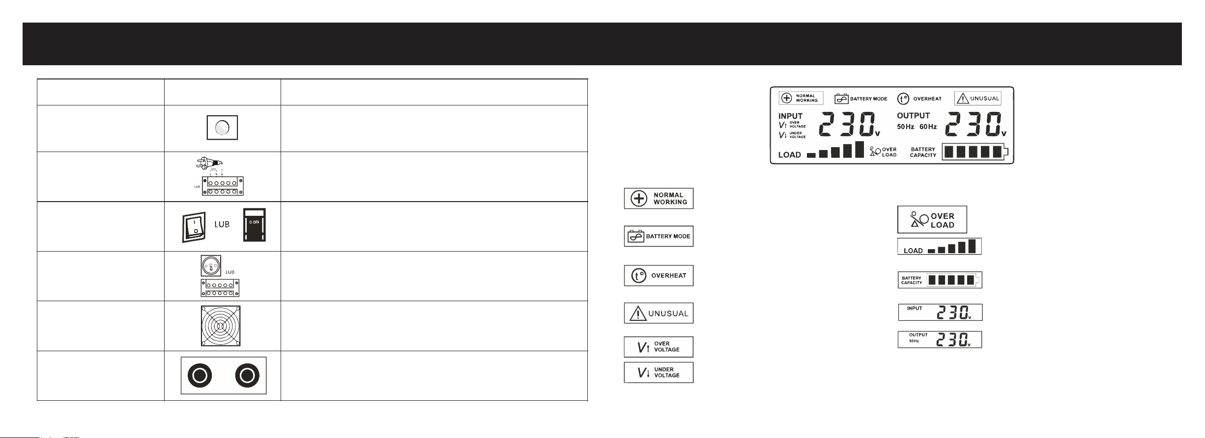
źIntuitive and simple operation thanks to the color LED display, which informs about the current operating
status of the device (input and output voltage, battery capacity, charging, etc.)
źConverter generates a pure sinusoidal voltage at the output, which makes it possible to work with
practically any type of load
źHigh battery charging current (exact values in the table with technical specifications)
źPossibility of changing charge current and switching off charger
źFast switching from mains supply to operating mode as a UPS enables uninterrupted operation of
connected devices
źIntelligent control of the cooling fan, depending on the actual temperature of the device and the operating
status of the inverter
źAC priority switch (network) / SOLAR (battery) (on some models)
INTRODUCTION
[email protected] (58) 341-05-06 | [email protected] (58) 341-38-80 | [email protected] (22) 100-42-99 [email protected] (58) 341-05-06 | [email protected] (58) 341-38-80 | [email protected] (22) 100-42-99 3
2
FIRST TIME START-UP
STARTING-UP INVERTER
1. Open the carton and check that all components are included and the device is undamaged. Disconnect mains cable from the
device.
2. Connect battery properly to the device according to the correct polarity (red wire + / black wire -).
3. Start the device with the ON / OFF button (hold down 5s until you hear a beep) and connect the plug to the mains socket.
4. Change the mains charger switch to the "I" position to start charging the battery and select AC PRIORITY.
5. Connect all devices that you want to use with the power supply, make sure they are turned off and turn them on one by one after
connecting.
6. On models with built-in priority switch, after connecting the regulator, select the SOLAR PRIORITY option.
SWITCHING-OFF THE INVERTER
1. Turn off one by one, all the devices connected to the inverter.
2. Change the charger switch to the "0" position to stop the battery charging process.
3. Hold down the ON / OFF button for 3 seconds to disconnect the inverter output.
4. Disconnect mains plug from the network.
5. Disconnect battery from the inverter.
ATTENTION
1.Be careful when connecting the battery, the voltage generated when reverse polarity happen can damage the inverter.
2. Do not overload the device above its nominal power. When connecting refrigerators, freezers and other induction appliances /
consuming more power on start-up, remember not to exceed 30% of the total power rating of the UPS.
3. Do not connect the device on the outdoors, avoid contact with water.
4. Remember to install the power supply in the right place, with access to fresh air and a minimum distance of 30 cm from each side
of the housing.
5. If you notice an incorrect operation / damage to the inverter, contact the manufacturer's service department.
6. If you want to test the device please do not unplug inverter from the mains. Instead turn off mains RCD switch in building to
observe proper work of the device. By unpluggin inverter from the mains, neutral - "zero" is cut off from the inverter, which can cause
incorrect work of the inverter.

[email protected] (58) 341-05-06 | [email protected] (58) 341-38-80 | [email protected] (22) 100-42-99 [email protected] (58) 341-05-06 | [email protected] (58) 341-38-80 | [email protected] (22) 100-42-99 5
4
OPERATION OF THE DEVICE
NAME
PICTURE
DESCRIPTION
Output switch
Pressing and holding the switch for more than 3 seconds will change the state of the
inverter to ON or OFF.
AC input cord
or
terminal
Connecting the plug to an electrical outlet allows the battery to be charged and to
power the output devices through the built-in voltage regulator.
Mains switch
If the device is connected to the mains supply and the switch is in the "I" position, the
battery will be charged and the output devices will be supplied from the mains.
Switching to the "0" position will start the inverter and supply the output devices from
the battery.
Output socket
or
terminal
Connect output devices to the terminal or terminal strip.
The maximum power of a single socket is 2000 W. If the power of the output devices
is higher, please connect them to the terminal block.
Ventilation fan
The cooling fan starts when the UPS inverter is running or when the battery is being
charged - when the temperature of the transistors exceeds 45 C
Battery input
The red terminal should be connected to the positive pole of the battery (+), and
black to negative (-). Changing the cables will prevent proper operation of the device.
- Normal operation mode, devices powered
directly from the 230 V BYPASS network
- No mains voltage, output devices powered
from a connected battery
- Overheating of the inverter, emergency
output devices are disconnected
- Incorrect battery voltage, short-circuit or
overheating of MOSFET transformers
- Mains voltage is too high
- Mains voltage is too low
- Inverter overload, too high power output
devices
- Inverter load level
- battery charge level, this indicator will
flash during charging
- Input voltage value
- Output voltage value and frequency
LCD DISPLAY ELEMENTS

[email protected] (58) 341-05-06 | [email protected] (58) 341-38-80 | [email protected] (22) 100-42-99 7
6
TECHNICAL PARAMETERS
Model 500 E 800 E 1000 E 1500 E 3000 E
Max power 500 VA 800 VA 1000 VA 1500 VA 3000 VA
Max constant power 300 W 500 W 700 W 1050 W 2100 W
Idle current (battery mode) < 1 A < 1 A < 1 A < 1 A < 1 A
Input
Voltage 140 ~ 275 VAC
Frequency 45 ~ 65 Hz
Output
Voltage 230 VAC ± 1% in battery mode; 230 VAC ± 8% in AC mode with AVR
Frequency 50 Hz ± 0.5 Hz
Voltage type PURE SINE WAVE
Distorions < 3%
Priority selection button
(AC / battery)
Charge current selection (5/10A )
Securities
overload, temperature, over and undervoltage,
before the battery is discharged, short-circuiting, before overcharging
Switching time AC / BATTERY ≤ 4ms
Battery voltage 12V DC 24V DC
Max. charge current [A] 10
Dimensions [W x L x H] [mm] 230 x 145 x 180 355 x 220 x 250
Weight 5,1 kg 6,5 kg 7,1 kg 10,7 kg 16,4 kg
YES
NO
YES NO
350 x 150 x 190
(only in E PLUS version) YES
YES YES YES NO
NO
(E PLUS: 2/5/10A)
AVR stabiliaztor
In network mode, the AVR stabilizer can increase or decrease the AC input voltage
to the right level. If a voltage exceeding the range appears on the AC input
(203 VAC +-1% - 239 VAC +- 1%) output voltage will be about ~ 213 VAC +-1% and will
grew adequately to the value of the input voltage
WARRANTY SERVICE COMMENTS
20 10
2000 E2000 E
2000 VA
1250 VA
< 1 A
14
FILL IN IF NEEDEED
(*) Cross incorrect
I agree to pay the cost of inverter repair due to:
* expiration of the warranty period / * warranty void
Before proceeding with the repair, service will inform by phone about the exact costs of the repair.
Please attach a copy of the purchase document (receipt or invoice) to the complaint.
The full regulations of service repairs can be found on our website www.voltpolska.pl
[email protected] (58) 341-05-06 | [email protected] (58) 341-38-80 | [email protected] (22) 100-42-99
DATE OF PURCHASE
SHIPPING ADDRESS
SIGNATURE / STAMP
DAMAGE DESCRIPTION
SERVICE COMMENTS
This manual suits for next models
6
Other Volt Polska Inverter manuals
Popular Inverter manuals by other brands

Northern Lights
Northern Lights L944D, M944W, NL944D2, M30CW, M944T, NL944T2, and... Operator's manual

Northern Lights
Northern Lights Lugger P984 Operator's manual

Ginlong
Ginlong Solis-100K-5G Installation and operation manual

SEW-Eurodrive
SEW-Eurodrive MOVITRAC LTP-B operating instructions

BOSSCO
BOSSCO MIG 200 operating manual

F&F
F&F FA-3X110 user manual