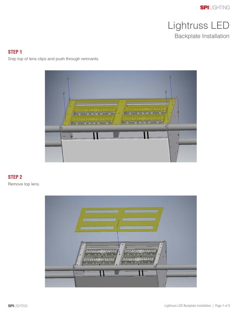
SPI LIGHTING NOVATO 2 x 2 FRAME BCE User manual
Other SPI LIGHTING Lighting Equipment manuals
Popular Lighting Equipment manuals by other brands
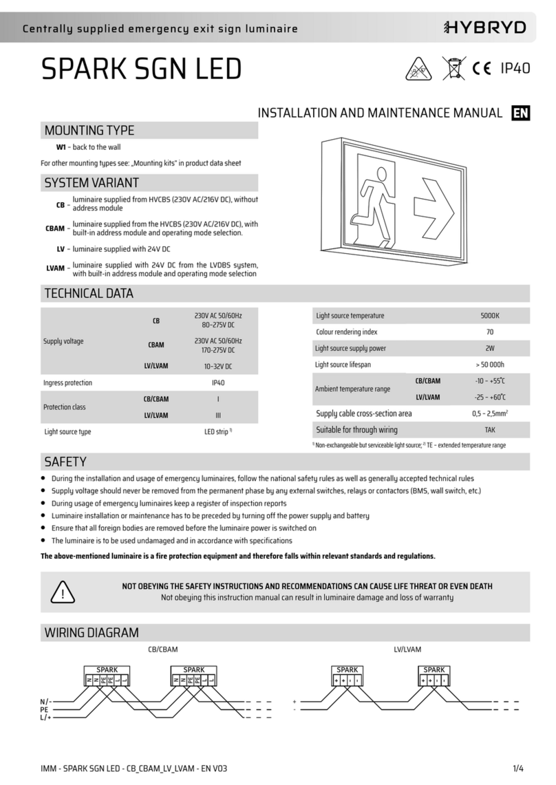
HYBRYD
HYBRYD SPARK SGN Installation and maintenance manual

Beghelli
Beghelli LOGICA LED LG FM quick start guide
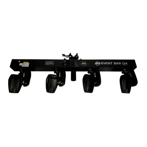
ADJ
ADJ EVENT BAR PRO user manual
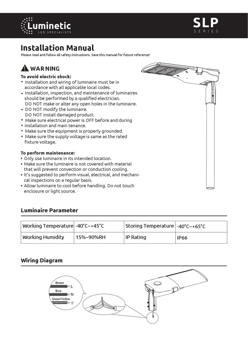
Luminetic
Luminetic SLP Series instruction manual
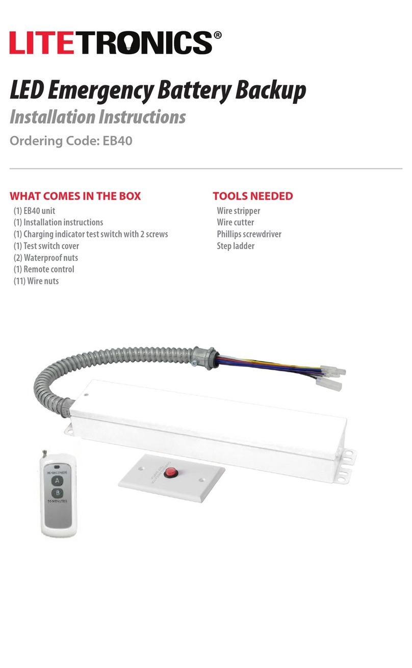
LITETRONICS
LITETRONICS EB40 installation instructions
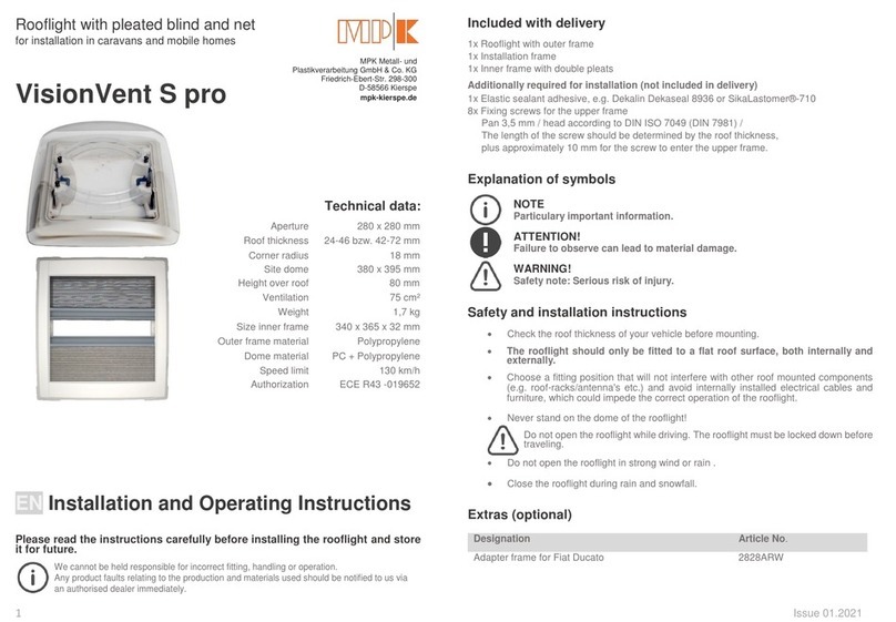
MPK
MPK VisionVent S pro Installation and operating instructions
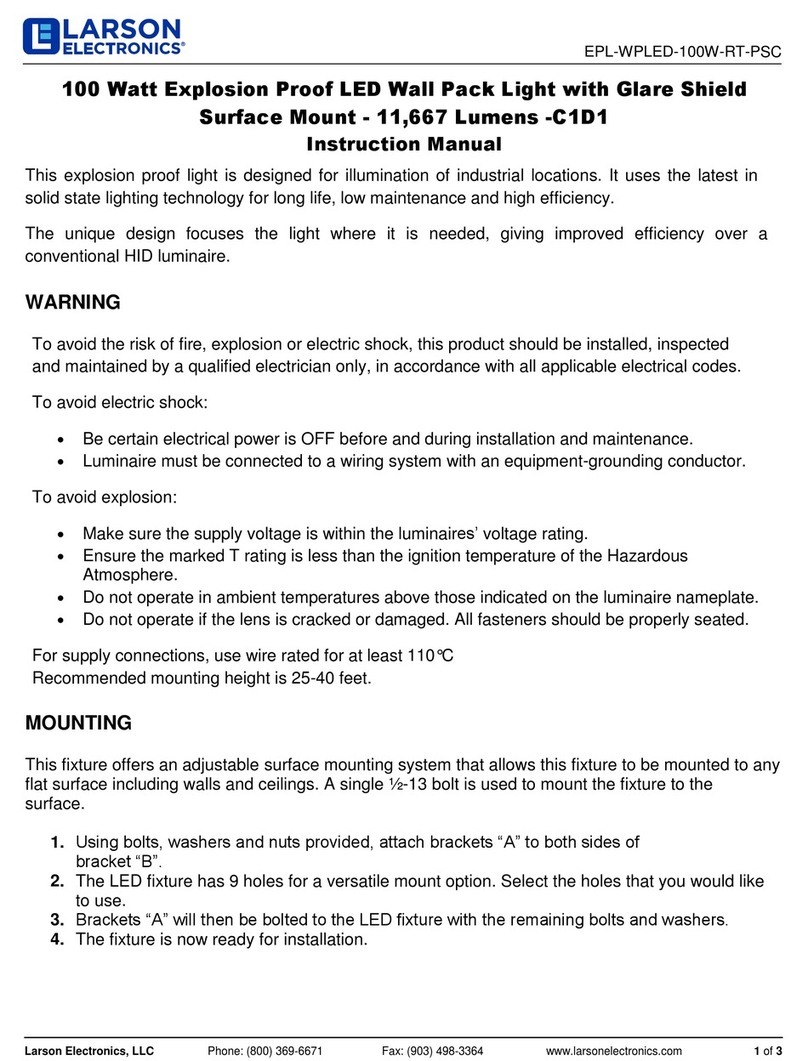
Larson Electronics
Larson Electronics EPL-WPLED-100W-RT-PSC instruction manual

Philips
Philips 69055/**/16 user manual

Nicols
Nicols GLAM LASER user manual
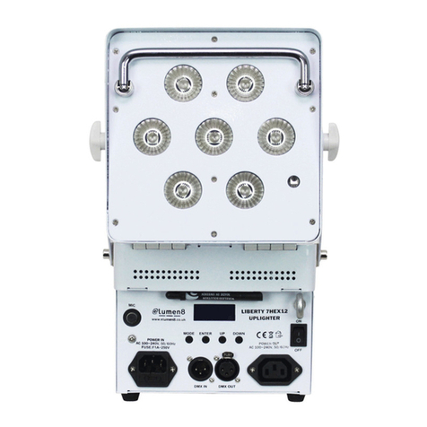
lumen8
lumen8 Liberty 7HEX12 user manual
ShowPro
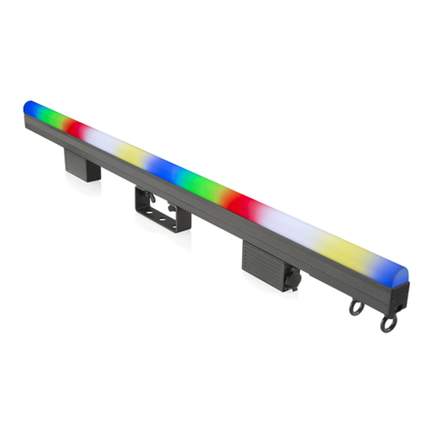
ShowPro Dreampix Driver 1800 IP user manual

Lightolier
Lightolier Lighting Systems CD7-11 Specification sheet
Larson Electronics
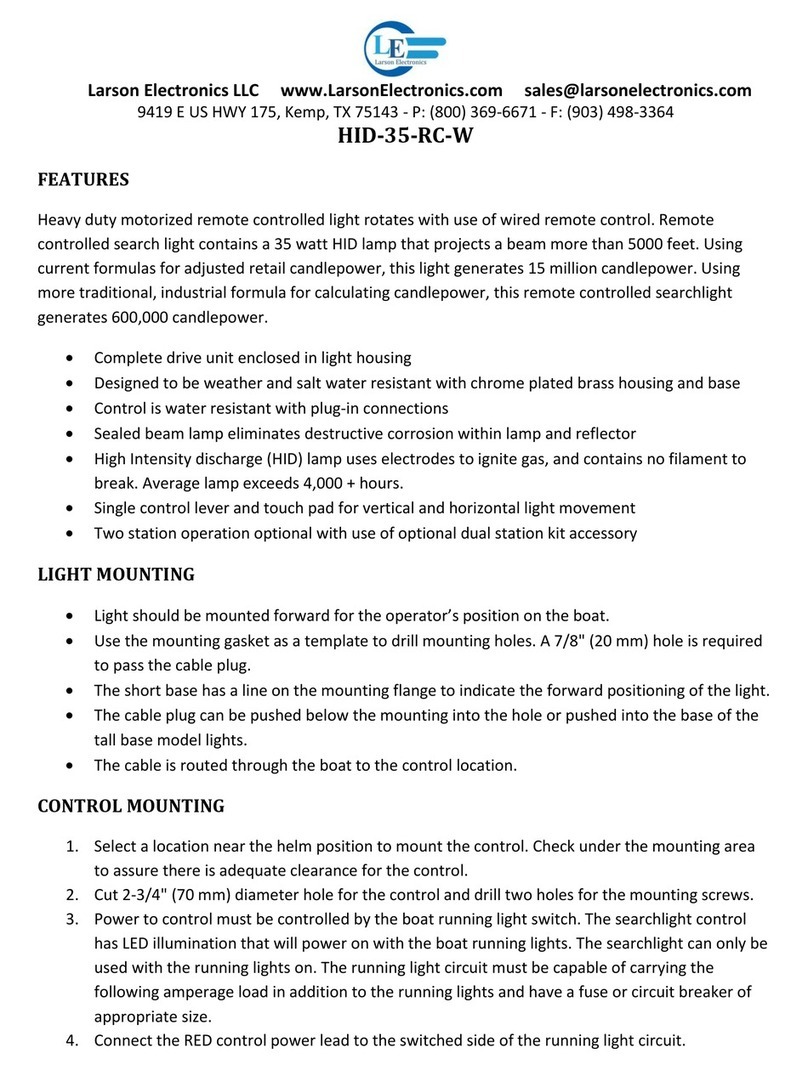
Larson Electronics HID-35-RC-W quick start guide
Vision-EL
Vision-EL NEON FLEX U150 Series user manual

Bestway
Bestway 65127 owner's manual
TPL VISION
TPL VISION BLBAR+ user guide

Whelen Engineering Company
Whelen Engineering Company TN Series installation guide

KEUCO
KEUCO Axess 35003 010737 Instructions for use


