manuals.online logo
Brands
  1. Home
  2. •
  3. Brands
  4. •
  5. HYBRYD
  6. •
  7. Lighting Equipment
  8. •
  9. HYBRYD SPARK SGN Manual

HYBRYD SPARK SGN Manual

Centrally supplied emergency exit sign luminaire
1/4IMM - SPARK SGN LED - CB_CBAM_LV_LVAM - EN V03
EN
IP40
SPARK SGN LED
INSTALLATION AND MAINTENANCE MANUAL
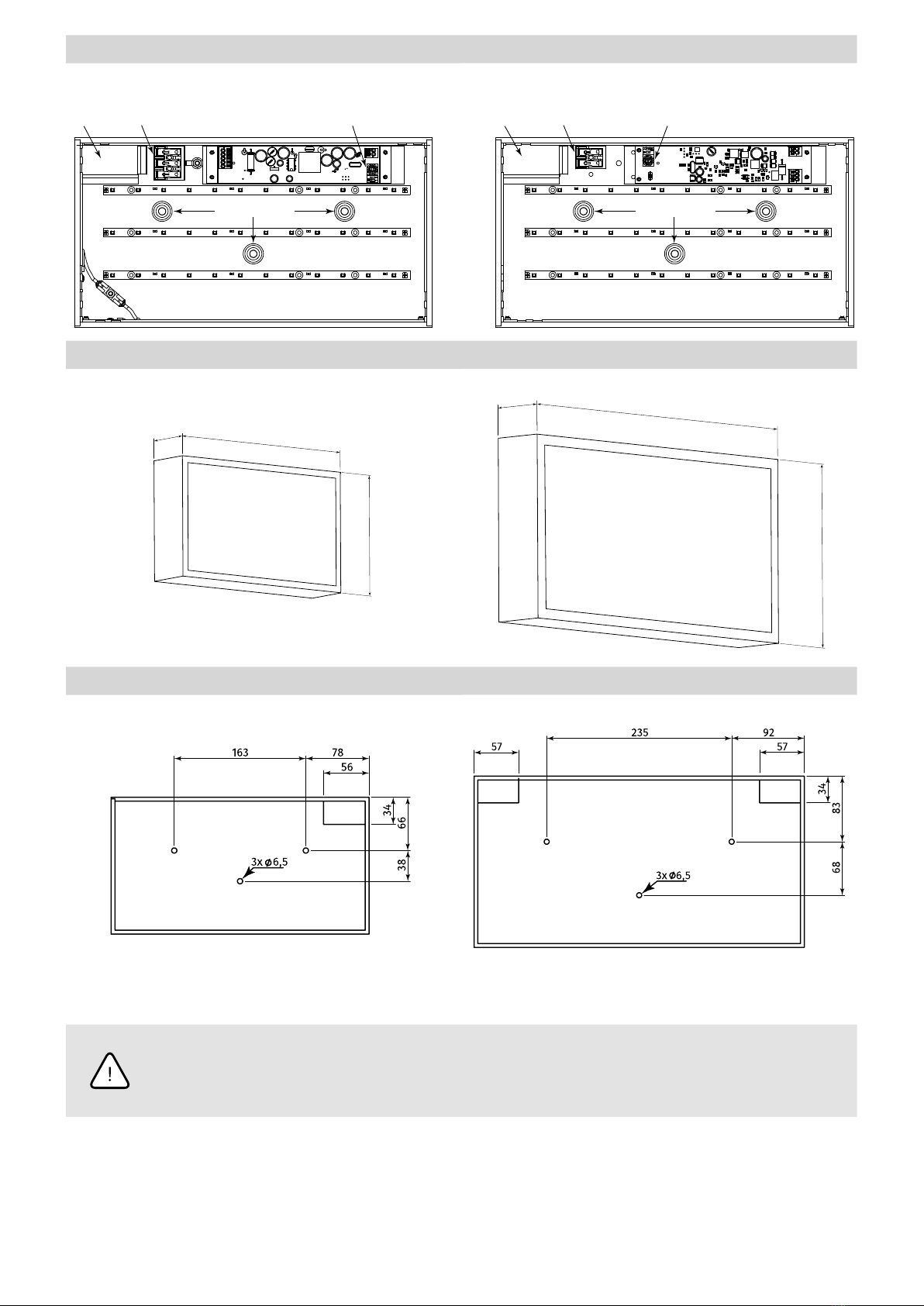
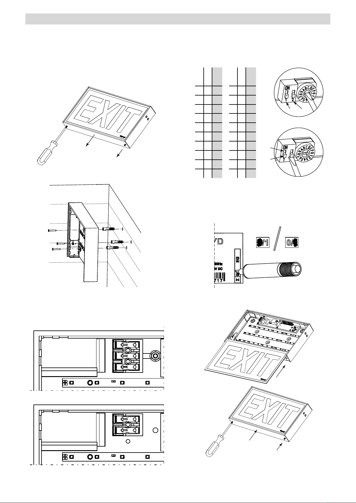
MOUNTING TYPE
W1 –
back to the wall
For other mounting types see: „Mounting kits” in product data sheet
SYSTEM VARIANT
CB –luminaire supplied from HVCBS (230V AC/216V DC), without
address module
CBAM –luminaire supplied from the HVCBS (230V AC/216V DC), with
built-in address module and operating mode selection.
LV – luminaire supplied with 24V DC
LVAM –luminaire supplied with 24V DC from the LVDBS system,
with built-in address module and operating mode selection
TECHNICAL DATA
Supply voltage
CB 230V AC 50/60Hz
80–275V DC
CBAM 230V AC 50/60Hz
170-275V DC
LV/LVAM 10–32V DC
Ingress protection IP40
Protection class
CB/CBAM I
LV/LVAM III
Light source type LED strip 1)
Light source temperature 5000K
Colour rendering index 70
Light source supply power 2W
Light source lifespan > 50 000h
Ambient temperature range
CB/CBAM -10 – +55˚C
LV/LVAM -25 – +60˚C
Supply cable cross-section area 0,5 – 2,5mm2
Suitable for through wiring TAK
1) Non-exchangeable but serviceable light source; 2) TE – extended temperature range
SAFETY
• During the installation and usage of emergency luminaires, follow the national safety rules as well as generally accepted technical rules
• Supply voltage should never be removed from the permanent phase by any external switches, relays or contactors (BMS, wall switch, etc.)
• During usage of emergency luminaires keep a register of inspectionreports
• Luminaire installation or maintenance has to be preceded by turning o the power supply and battery
• Ensure that all foreign bodies are removed before the luminaire power is switched on
• The luminaire is to be used undamaged and in accordance withspecications
The above-mentioned luminaire is a re protection equipment andtherefore falls within relevant standards and regulations.
NOT OBEYING THE SAFETY INSTRUCTIONS AND RECOMMENDATIONS CAN CAUSE LIFE THREAT OR EVEN DEATH
Not obeying this instruction manual can result in luminaire damage and loss of warranty
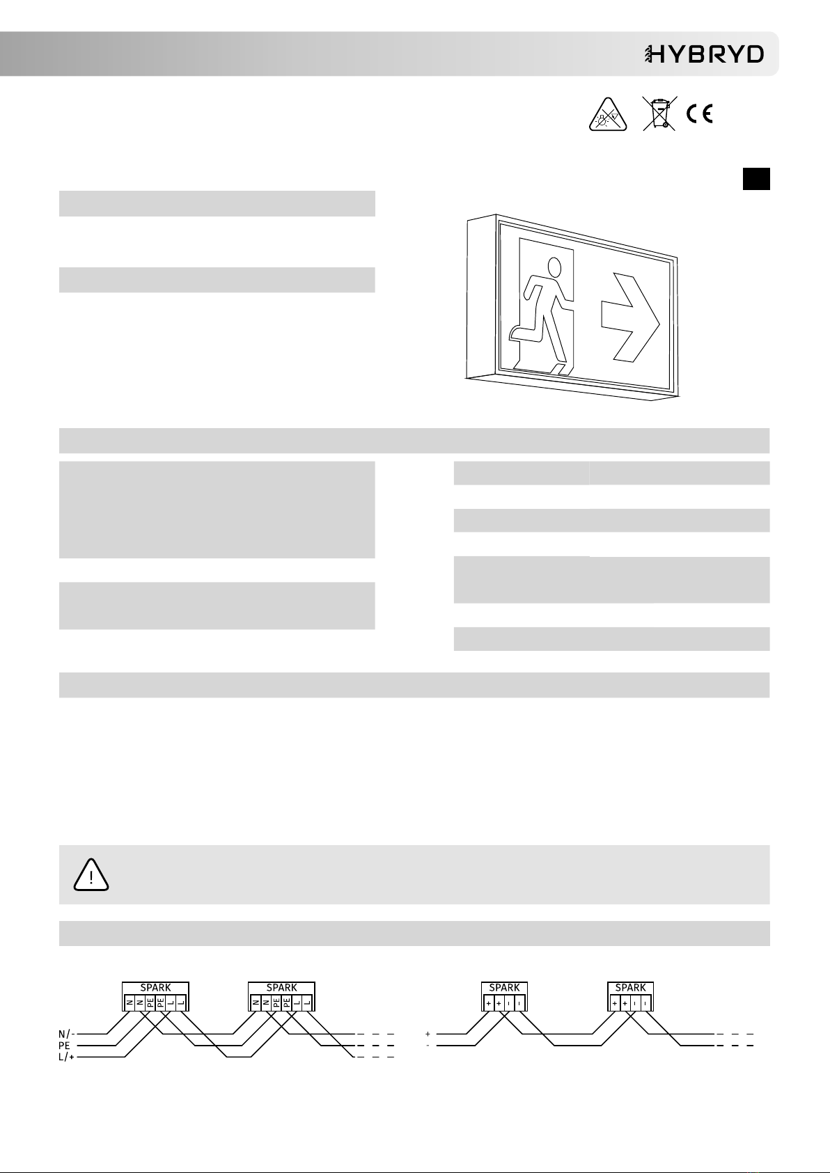
WIRING DIAGRAM
CB/CBAM LV/LVAM
2/4 www.hybryd.pl
LUMINAIRE CONSTRUCTION
CB/CBAM LV/LVAM
Cable
gland Power supply
connector Address and operating
mode switch (only CBAM)
Mounting holes
+
-
Cable
gland Power supply
connector Address and operating
mode switch (only LVAM)
Mounting holes
DIMENSIONS (mm)
30x15 40x20
41
420
218
41
320
170
30x15
40x20
41
420
218
41
320
170
30x15
40x20
MOUNTING DIMENSIONS (mm)
30x15 40x20
BEFORE ANY INSTALLATION OR MAINTENANCE WORK IS PERFORMED ON THE LUMINAIRE
THE POWER SUPPLY SHOULD BE DISCONNECTED
All installation and maintenance procedures can be performed only by qualied,
properly trained and if appropriate, certied sta
3/4IMM - SPARK SGN LED - CB_CBAM_LV_LVAM - EN V03
INSTALLATION
1. Unpack the luminaire after transport and verify its condition.
2. Drill holes in wall according to luminaire mounting hole
spacing, so that power cables can be pushed freely into the
luminaire through the cable glands. Use dowels or screws,
appropriate for the material luminaire is being mounted to.
3. Unscrew the two M3 screws xing the bottom part of
luminaire and remove it, at the same time, remove the plate with
pictogram and then screw the part back on to facilitate assembly.
4. Carry out the power cable through the cable gland in lumina-
ire. Screw the luminaire to the wall using mountingholes.
5. Connect the power supply cables according to the appropria-
te wiring diagrams, strip 7-8mm of wire copper insulation. Cab-
les should be carefully arranged so that no shadow is present on
pictogram. Pay special attention to the luminaire supplyvoltage!
CB/CBAM
N
L
PE
LV/LVAM
–
+
6. In case of luminaires with built-in address module:
a. set luminaire address using the rotary switch SW1 and
second slider of SW2 switch (SW2-2).
Setting the SW2-2 position to „1” means adding 10 to the
address, according to the table below.
SW2-2
SW1
Address
SW2-2
SW1
Address
0 1 1 1 1 11
0 2 2 1 2 12
0 3 3 1 3 13
0 4 4 1 4 14
0 5 5 1 5 15
0 6 6 1 6 16
0 7 7 1 7 17
0 8 8 1 8 18
0 9 9 1 9 19
0 A 10 1 A 20
SW2 SW1
SW2
SW1
„1“
„0“
SW2-1 SW2-2
b. using the rst slider of SW2 switch (SW2-1) select the
operating mode. Position „1”–maintained(M), position „0”
– non-maintained (NM).
7. Mark the operating mode on the luminaire label. Mark 0for
maintained mode
(M)
and 1for non-maintained mode
(NM)
.
M NM
8. Unscrew the bottom part of luminaire, fold down. Insert the
plate with pictogram. Screw the bottom part of luminaire back.
9. Perform the commissioning procedure.
4/4 www.hybryd.eu
COMMISSIONING
After all installation procedures are nished, luminaire operation needs to be veried.
Follow the instructions below:
1. Switch the luminaire power supply on the HVCBS or LVDBS system.
2. For luminaires without built-in address module (CB, LV):
a. Leave luminaire operating and verify light source should be operating.
b. Turn o luminaire power supply.
3. For luminaires with built-in address module (CBAM, LVAM):
a. Congure the HVCBS/LVDBS system.
b. Congure HVCBS/LVDBS circuit as maintained and if required, switch between maintained and non-maintained luminaire operating
mode (see luminaire control on previous pages).
c. Run the functional test on HVCBS/LVDBS system.
d. Verify luminaire operation. The light source should operate properly.
e. Verify if the HVCBS/LVDBS system reports proper luminaire operation.
MAINTENANCE
Luminaire should be cleaned with a damp cloth according to building maintenance plan.
Do not use abrasive cleaners, solvents, substances and cleaning agents containing alcohol to clean the lampshade.
The light source used in this luminaire may only be replaced by the manufacturer, his service agent or a similar qualied person.
STORAGE
The luminaire should be stored no longer than 6 months from the date of purchase, in a dry place with an ambient temperature range
-10–+30˚C.
WARRANTY
Warranty is valid and enforceable only when manufacturer’s recommendations are preserved, and the installation and usage are proper.
Warranty is granted for a period of 12 months from the date of sale, unless the luminaire has been sold under dierent contract conditions.
The warranty is excluded in case ofmisuse, unsuitable use, wrong connection or mechanical defects of the luminaire caused by the client.

Other HYBRYD Lighting Equipment manuals

HYBRYD CRYSTAL LED Manual

HYBRYD

HYBRYD CRYSTAL LED Manual

HYBRYD CRYSTAL LED Manual

HYBRYD

HYBRYD CRYSTAL LED Manual

HYBRYD PRIMOS CLA LED 0140 Manual

HYBRYD

HYBRYD PRIMOS CLA LED 0140 Manual

HYBRYD ALU SGN LED Manual

HYBRYD

HYBRYD ALU SGN LED Manual

Popular Lighting Equipment manuals by other brands

Brighter Smart Spot 150 LED user manual

Brighter

Brighter Smart Spot 150 LED user manual

Traxon e:cue SYMPL pro Node Instructions for use

Traxon

Traxon e:cue SYMPL pro Node Instructions for use

Ledj BlockBuster 6 manual

Ledj

Ledj BlockBuster 6 manual

LITESHEET BriteCor AC BTS Series installation manual

LITESHEET

LITESHEET BriteCor AC BTS Series installation manual

Cameo STORM FX user manual

Cameo

Cameo STORM FX user manual

Flash F7100443 user manual

Flash

Flash F7100443 user manual

MA lighting 4Port Node onPC user manual

MA lighting

MA lighting 4Port Node onPC user manual

Datalogic SG-BODY Series quick guide

Datalogic

Datalogic SG-BODY Series quick guide

Laserworld GREEN-50E user manual

Laserworld

Laserworld GREEN-50E user manual

UFO Nova Light Source Product user guide

UFO

UFO Nova Light Source Product user guide

Hama 00176606 operating instructions

Hama

Hama 00176606 operating instructions

Satco NUVO 67-120 Installation and safety instructions

Satco

Satco NUVO 67-120 Installation and safety instructions

Robe ColorWash 575E AT Service manual

Robe

Robe ColorWash 575E AT Service manual

WESTEK BL-PCCT-W owner's manual

WESTEK

WESTEK BL-PCCT-W owner's manual

Lightolier 1000 SERIES Installation

Lightolier

Lightolier 1000 SERIES Installation

Raytec RL F 25 installation guide

Raytec

Raytec RL F 25 installation guide

Current REEF R24 quick start

Current

Current REEF R24 quick start

Honeywell 290087.1 manual

Honeywell

Honeywell 290087.1 manual

manuals.online logo
manuals.online logoBrands
  • About & Mission
  • Contact us
  • Privacy Policy
  • Terms and Conditions

Copyright 2025 Manuals.Online. All Rights Reserved.