XLifter X1 User manual

World’s first
Air-suspension controller with self-levelling feature
for the D3, D4 and RRS Land Rover vehicles
User manual
(Installation & user guide)

XLifter model X1, user guide, ver. 1.41, firmware ver. 0.98
Reco, spol. s.r.o., Na hlinach 6, 18200 Prague, Czech Rep., https//www.xlifter.com, info@xlifter.com Page 1
Table of contents:
1. Legal disclaimer 2
2. General description 2
3. Safety information 3
4. Installation 4
4.1. Package Contents 4
4.2. Installation - general description and overview 4
4.3. EAS Unit Installation 5
4.4. Control Module Installation 8
4.5. Vehicle type and calibration settings 9
4.6. Dismantling XLifter from vehicle 9
5. Instruction for use 10
5.1. Function Lifter: Height adjustment in predefined programs. 10
5.2. Function Lifter – free: Adjustment from -40 to +75 mm in 5 mm steps. 11
5.3. Function levelling: self-level the vehicle. 12
5.4. Menu “Settings”: User settings. 14
6. Calibration 15
7. Service menu 16
7.1. Entering the Service menu 16
7.2. Service menu items description 17
8. Firmware update 18
9. Technical specifications 20
10. FAQ & Troubleshooting 21
11. Warranty conditions 23
12. Contacts and support 23
Quick orientation in this manual:
Congratulations, you are actually reading the manual! I'm so glad you decided to read the
instructions to your new XLifter. Many users casually dismiss instructions and seek to
figure it out on their own – which is perfectly possible, we all do! But, even then I’ve built
the product as simple and intuitive as possible, there are some useful tricks, hints,
warnings and “behind the scenes” info, which I’ve collected over the years for you into this
manual. It’s worth to read it. Dig in, mark it up, cut out your favourite sections. It's going to
be a wild ride.
Chapter 4 is all about installation, skip it if the XLifter is already installed. The most
important is the chapter 5 - Instruction for use, where the XLifter daily-use functions are
described. Please consider reading it again after a few days of hands-on experience.

XLifter model X1, user guide, ver. 1.41, firmware ver. 0.98
Reco, spol. s.r.o., Na hlinach 6, 18200 Prague, Czech Rep., https//www.xlifter.com, info@xlifter.com Page 2
1. Legal disclaimer
You are hereby provided with an air-suspension controller for Land Rover vehicles – product named
XLifter (hereinafter as the „device” or „XLifter“).
XLifter is an additional device able to change the air-suspension adjustment and able to change
other parts of your car set-up by the car´s manufacturer.
XLifter is not a device approved and designed for installation into vehicles intended to be operated
on public roads namely pursuant to Act. no. 361/2000 Coll, as amended. The manufacturer does not
assume any liability deriving from technical requirements for operation of vehicles on public roads
in case you decide to use this product in traffic on public roads or anywhere else, where operation
of this device may be considered as unauthorized, whether in the Czech Republic or in any other
jurisdiction. The end-user assumes all liability connected to use of the device on public roads,
derived namely from the mandatory technical requirements for operation of vehicles on public
roads provided by Act. No. 56/2001 Coll and regulation no. 341/2014 Coll.
By installation of the device the end-user discharges the manufacturer from any liability connected
to any influence or damage (whether financial or immaterial) of the provided product on other
systems, parts or components of the vehicle (whether mechanical or electronical). By installation of
this product the end-user also acknowledges that this product is meant to be used in controlled
conditions, namely at low speeds and with increased caution.
The end-user undertakes to inform about installation of the device any prospective future owner of
the respective vehicle equipped with the device.
By installation of the device you acknowledge the above-mentioned and agree with the above-
mentioned terms. Please use the XLifter only in off-road conditions and not on public roads.
2. General description
XLifter is an advanced air-suspension controller for the Land Rover vehicles. XLifter allows
you to take the air suspension capabilities of your Land Rover to the maximum, making
your off-roading or expedition travelling greater experience.
XLifter gives you more detailed control over the vehicle height settings. Raising the
vehicle, even above the „Off-road“ height, helps you to tackle difficult terrain. XLifter is not
limited by the 40 Km/h speed limit, so travelling over long stripes of sand, green lanes or
dirty roads will be fun more fun. Also, XLifter keeps selected lift settings permanently, you
can fit bigger tires easily. Lowering the vehicle slightly improves cornering stability and
aerodynamics. Lowering below the original access height makes possible the entering of
low-clearance garages or ferries and makes cargo loading easier.
XLifter unique self-levelling feature makes your in-car or in a roof top tent sleeping more
comfortable while expedition travelling.
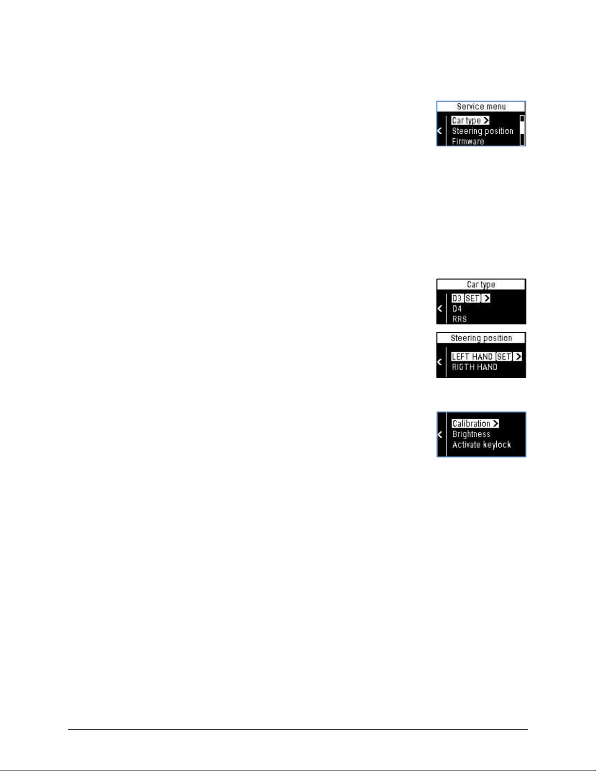
XLifter controls are intuitive and comfortable. The control module with graphical OLED
display and physical buttons was optimized for off-road handling.
XLifter EAS unit communicates with the control module wirelessly. Installation to your
vehicle is simple and XLifter is fully removable. No drilling, soldering, or in-car wiring is
required.
XLifter is designed for Land Rover Discovery 3 (LR3), Discovery 4 (LR4) and Range Rover
Sport (model L320) vehicles.

XLifter model X1, user guide, ver. 1.41, firmware ver. 0.98
Reco, spol. s.r.o., Na hlinach 6, 18200 Prague, Czech Rep., https//www.xlifter.com, info@xlifter.com Page 3
3.
Safety information
This manual contains important information on the installation (in the installation guide) and use of
the XLifter. Please take some time to read this manual to take full advantage of the XLifter features
and to ensure that you know how to operate them safely. Use the XLifter only for its intended
purpose as described in this user manual.
What the safety symbols in this user manual mean:
This symbol represents potential general warnings, hazards or unsafe practices that may
result in possible damage to vehicle or vehicle systems. Please read texts marked by this
symbol carefully and proceed according to provided instructions to avoid risks.
Warning: This symbol, with the word "warning" attached above or next to the symbol,
indicates situations where non-compliance may result in serious injury or damage to the
equipment or vehicle.
Safety instructions are described on a continuous basis in the description of each XLifter function.
However, below is an overview of the most important ones:
General warnings:
Warning: Ensure that the XLifter is operated only by a person familiar with this manual. If
another person is driving, please activate the Keylock function before, as a safety measure.
(see chapter 5.4)
Warning: If an XLifter is left installed in the vehicle when it is sold, notify the new acquirer
and familiarize him with this manual. Please keep this manual permanently in the vehicle
in an accessible location for a future reference.
Warning: Do not use XLifter while driving on the public roads. Do not lower or raise the
vehicle at high speeds.
Warnings for the lifter and lifer-free functions:
Warning: when in extreme lifts - “Sky Rocket” (+75 mm) or any lift program while the
“original” vehicle height is Off Road, please be gentle with the accelerator pedal in case,
when you have low-range engaged and you are steering hard to the left or right. The
driveshafts to CV joints angle is very high. Don’t overstress the CV joints.
Warning: In the original “Off Road” vehicle height, it is not recommended to lift the vehicle
with XLifter by more than +25 mm permanently due to possible increase wear of the air-
springs.
Be gentle to the vehicle compressor! The compressor will overheat when the vehicle is
lowered/raised several times (3x is usually enough) in a row. When overheated, the Land
Rover EAS unit inhibit further operation until cooled. Cooling takes about 10 minutes.
Warning for the levelling function:
Warning: NEVER EVER start the levelling function while driving!!! The wheels height will
be set differently, which results to potentially dangerous situation. Start levelling only when
the vehicle is stationary!
When active, the levelling function must be exited before driving! Otherwise you start
driving with unbalanced wheel heights, exposing yourself to potentially dangerous
situations and you may even damage your vehicle! NEVER leave the camping place with
levelling still active!
Do not engage electronic park break (EPB) before or during levelling. It will cause
unnecessary tension in park break cables, which will counteract wheel movement. You
may use the “P” gear instead in the automatic gearbox vehicles.
Warning: Close all doors before starting the levelling function to prevent possible damage
due to contact with surrounding ground.

XLifter model X1, user guide, ver. 1.41, firmware ver. 0.98
Reco, spol. s.r.o., Na hlinach 6, 18200 Prague, Czech Rep., https//www.xlifter.com, info@xlifter.com Page 4
4. Installation
4.1. Package Contents
1x XLifter EAS installation
1x Cable harness with the bypass connector
1x XLifter
control module
1x Velcro strip for easy control module installation
1x User and installation manuals
1x XLifter sticker
4.2. Installation - general description and overview
The XLifter device consists of 2 main components - the control module and the EAS
installation unit (EAS stands for Electronic Air Suspension). The control module (display
unit with buttons) is used to control all settings and to inform the user of the operating
status. The EAS unit serves to adjust the wheel height sensor signals and vehicle tilt
measurements. Communication of the control module and the EAS unit is wireless.
The control module is installed anywhere in a suitable place in the interior of the vehicle.
The control module needs to be connected to an ignition-switched 12V power supply
(cigarette lighter socket). Advanced users may cut the power connector and connect the
cable to appropriate 12V junction point. Installation with all cables hidden will look more
aesthetically and the lighter socket will not be blocked.
The XLifter EAS unit is installed near the original air suspension control unit and connects
with it via the supplied cable harness. The XLifter EAS unit is mechanically attached to the
body of the vehicle after installation, thus serves also as an accurate tilt sensor.
Quick installation overview in 5 steps:
1. Install the XLifter EAS unit and connect the cable harness
2. Plug the control module power to 12V socket
3. Set the appropriate vehicle type (D3, D4, RRS)
4. Set the Steering position (left or right-hand side)
5. Perform the calibration procedure

XLifter model X1, user guide, ver. 1.41, firmware ver. 0.98
Reco, spol. s.r.o., Na hlinach 6, 18200 Prague, Czech Rep., https//www.xlifter.com, info@xlifter.com Page 5
4.3.
EAS Unit Installation
The installation procedure of the EAS unit is listed for the Discovery 3/4 vehicle. For the
Range Rover Sport, the original EAS control unit is located about 10cm lower than in the
Discovery. For convenient access to the connectors, it is necessary to remove the footwell
and the adjacent left panel (the one with the front bonnet open handle).
Estimated installation time:
● The EAS unit installation should take approximately 10 - 30 minutes.
Tools required:
● Common cross-head screwdriver (e.g. original from Land Rover equipment).
● Flashlight - Installation area lighting
EAS unit installation procedure:
1. Disconnect the vehicle battery according to the vehicle user manual
a. Make sure the ignition is off.
b. Disconnect the + pole.
c. Wait 1 minute.
Note: This point is not required, installing without disconnecting the battery does not
cause problems.
2. Dismantle the lover dashboard cover panel under the steering wheel.
If installing to the Range Rover Sport L320, see the note above.
a. Unscrew the two screws holding the cover.
b. Pull in the direction of the RIGHT green arrow (see picture below) to release a
mechanical connector connecting the cover to the central tunnel.
c. Hold the cover panel in the centre. Pull down and towards you slightly to move
the cover panel down for approximately 10 centimetres.
d. Disconnect the light connector located on the left side (right for RHD vehicles) of
the cover.
e. Remove the entire cover.

XLifter model X1, user guide, ver. 1.41, firmware ver. 0.98
Reco, spol. s.r.o., Na hlinach 6, 18200 Prague, Czech Rep., https//www.xlifter.com, info@xlifter.com Page 6
3. Disconnect wiring harnesses from the original LANDROVER EAS unit
The Land Rover EAS unit is located at the left
(right for RHD vehicles) inner side of car
body – approx. in the middle of imaginary
line between the end of A pillar and drivers
footrest.
Use a flashlight to illuminate the work area.
a. Disconnect the A and B connectors.
Disconnect the connector by pushing the connector lock and pulling it
outwardly (with some light wobbling). The A and B connectors are the most left
and right ones.
b. Place the disconnected cable harnesses temporarily behind the rest of the cables
in area. This will help you to create enough space for a comfortable XLifter EAS
unit installation.
4. Install the XLifter EAS unit
Prior to sticking the XLifter EAS unit into its final position, it may be a good idea to
practice placing the EAS unit to a correct position for a few times, without having
removed the 3M reclosable fastener protective foil. The 3M fastener sticks very firmly
once placed in a position and makes it very uneasy to replace it once stuck in a place.
The XLifter EAS unit is equipped with a tilt sensor. The unit must be positioned at least
approximately according to the procedure described. Otherwise (sticking it horizontally
or "upside down"), the leveling function will not work properly.
a. On the unprinted side of the EAS
unit, remove the adhesive protection
foil from the 3M fasteners.
b. Place and stick the XLifter EAS unit
to the original Land Rover EAS unit
as shown.
● The printed side of the unit faces the
centre tunnel.
● The arrow marked THIS SIDE UP is
pointing up.
● For the sticking itself, it takes a few
seconds with strong force required.

XLifter model X1, user guide, ver. 1.41, firmware ver. 0.98
Reco, spol. s.r.o., Na hlinach 6, 18200 Prague, Czech Rep., https//www.xlifter.com, info@xlifter.com Page 7
5. Connect the XLifter cable harness
a. Connect the connectors A(out) and B(out)
of the supplied cable harness to the original
Land Rover EAS unit.
b. Plug the previously disconnected
connectors to the connectors A(in) and
B(in) of the supplied cable harness.
c. Plug the connector C to the XLifter EAS
unit.
NOTICE:
Place the "loose" cables in a way so they do
not move freely. If necessary, use any
tightening strap (not included). This
prevents them from "knocking out" in long-
term operation.
None of the connectors are
interchangeable. You cannot connect the
cable harnesses in a wrong way.
All connectors must be fully inserted as
far as they will go, as shown. Some
connectors, especially B ones, require
slightly more force to fully connect.
Incomplete insertion is the source of unpredictable problems, please pay
attention here!
6. Connect the vehicle battery in accordance with the vehicle user manual
● Only if you disconnected it in step 1.
● Discovery 4: The “Suspension error” will be displayed. Cycle the ignition to clear it.
● Discovery 3: The “Suspension error” should clear itself in few seconds.
7. Check the status LED on the XLifter EAS unit
● The green status LED flashes at a fast pace - 2x per second, indicating readiness for
operation and awaiting wireless connection from the control module.

XLifter model X1, user guide, ver. 1.41, firmware ver. 0.98
Reco, spol. s.r.o., Na hlinach 6, 18200 Prague, Czech Rep., https//www.xlifter.com, info@xlifter.com Page 8
8. Re-install the lower dashboard cover panel
● Re-install the cover in reverse manner when dismantling it (just follow the
instructions from step 2 in a reverse order).
● Do not forget to connect the light connector.
● When installing the cover back, it is necessary to "hit" with three centreing
protrusions on the rear of the cover to the holes on the wall behind the steering
pedals.
● The cover needs to be slightly bent again, it is better to first install the part on the
side of the EAS unit and then the side at the centre tunnel.
4.4. Control Module Installation
The control module and the EAS unit communicates wirelessly, therefore choosing a
suitable location is freely at your will.
The control module is powered from ignition-switched +12V power supply (e.g. cigarette
lighter socket etc.). If you have enough skills and wish to do so, you can cut off this
connector and hard-wire it into another suitable 12V source later (e.g. cigarette socked
wiring behind centre dashboard), thus making the wiring invisible. The power cable has
standard colours – red for + pole and black is – pole. The control module is equipped with
reverse-polarity protection circuit.
Control module installation procedure:
1. Connect the control module power
Plug the 12 V power plug into the cigarette lighter socket.
Attach the control module with the supplied installation material (Velcro) or at
your own discretion to a suitable location (or do this later).
2. Quick-check the control module
● Turn the ignition ON
● The animated logo and the scrolling XLifter EAS unit wireless search indicator
appears on the control module display.
● The control module and the XLifter EAS unit were already paired for you. The
communication should be established within max. 10 seconds. Please allow up to
20 seconds if the EAS unit was just powered up by connecting the C connector, or
by connecting the vehicle battery.
● When communication is established, the XLifter "home
screen" appears. It will show zero lift and "Not Calibrated" info.

XLifter model X1, user guide, ver. 1.41, firmware ver. 0.98
Reco, spol. s.r.o., Na hlinach 6, 18200 Prague, Czech Rep., https//www.xlifter.com, info@xlifter.com Page 9
4.5. Vehicle type and calibration settings
Before using the XLifter for the first time, it is necessary to set the type of your vehicle and
run the calibration procedure.
1. Enter the service menu.
The control module displays the service menu if any button is
held pressed when the control module power is turned on.
a) Pull the control module's 12V plug from the cigarette lighter
socket (the control module display turns off).
b) Press and hold down any control module button and reinsert the power
plug. The control module displays the service menu. Then release button.
In case of any troubles with entering the service menu, or in case the Control module
has been „hardwired“ to a +12V supply, please read the chapter 7.1 Entering the
Service menu. The procedure is described there with more details and options.
2. Use the buttons and to select "Car Type" and set the
corresponding vehicle type. Then press to return to the
service menu.
3. If you have a right-hand drive vehicle, invoke "Steering position"
and set "RIGHT HAND". Then press to return to the service
menu.
4. Press to quit the service menu.
5. Calibrate the XLifter (see chapter 6 Calibration for details).
From home screen, press to enter to the XLifter main menu,
select „Settings” and press , then select „Calibration“.
Congratulations! The installation is finished.
4.6. Dismantling XLifter from vehicle
Of course, XLifter can be dismantled from the vehicle. The procedure is the opposite of the
installation, with the following differences:
● In case of temporary disassembly, you may leave the XLifter cable harness still
installed. In such case, you only disconnect the connector C from the XLifter EAS
unit (see the manual for installation, point 5c, chapter 4) and then plug the bypass
connector into disconnected C connector.
● The EAS unit is detached from the 3M reclosable fastener by a strong pull
perpendicular to the printed side (direction to the centre console). You cannot
separate the fastener by pulling the EAS unit to either side. Do not remove the
fastener left stuck on the original EAS unit. It holds very well. For reassembly into
another vehicle, use a new piece of fastener (not supplied). It is a 3M SJ3550 3M
reclosable fastener, 25 mm wide, 39 head per cm2.

XLifter model X1, user guide, ver. 1.41, firmware ver. 0.98
Reco, spol. s.r.o., Na hlinach 6, 18200 Prague, Czech Rep., https//www.xlifter.com, info@xlifter.com Page 10
5. Instruction for use
The XLifter control module will allow you to set all required parameters and informs you
about operating status. Think of it as a smart wireless remote for the air suspension.
The control module has four arrow buttons . In general, the buttons are used
to change selected parameter and for scrolling in menus. Right button invokes menu
or activate selected item. The left button serves usually as back or cancel.
The XLifter home screen shows the most important status information:
Selected lift program / lift / units
The “original” vehicle height
indicator shows the position
selected on the vehicle centre
console as shown:
= Off Road height
= Standard height
= Access height
Shock absorbers infographics.
The outer edge represents the
shock absorber housing, the
white column is inner rod
coupled with the wheel.
The wheel target height
indicator shows ideal wheel height in selected program when vehicle is on ideal flat
surface.
Pressing the whilst in home screen increase/decrease lift program or change
height in 5mm step, according to the active lifter function.
Overview of XLifter functions
All common features are available from the main menu.
The main menu is invoked by pressing when at home screen.
Pressing when in main menu returns to the home screen.
5.1. Function Lifter: Height adjustment in predefined programs.
1. Press to access the main menu.
2. Use to select “lifter”, then press to activate.
3. Use to change the lift program.
● Sky Rocket – height + 75 mm
● Off Road – height + 55 mm
● One Inch Lift – height + 25 mm
● Aesthetic Lift – height + 15 mm
● Disengaged – height + 0 mm (default value)
● Highway Drop – height - 15 mm
● One Inch Drop – height - 25 mm
● Super Drop – height - 35 mm

XLifter model X1, user guide, ver. 1.41, firmware ver. 0.98
Reco, spol. s.r.o., Na hlinach 6, 18200 Prague, Czech Rep., https//www.xlifter.com, info@xlifter.com Page 11
5.2.
Function Lifter – free:
Adjustment from -40 to +75 mm in 5 mm steps.
1. Press to access main menu and select “Lifter-free”,
then press to activate.
2. Use the buttons to select desired height in 5 mm steps.
● The currently set lift value is displayed
● Holding the or button activates the button auto-repeat.
● In Lifter-free mode, "Free mode" is displayed as the program name.
Warnings and limitations to the "Lifter" and “Lifter-free” functions
●
The “original” Land Rover vehicle height control by the lever (D3) or buttons (D4) on the
center console remains unchanged after XLifter installation.
●
The selected XLifter lift value is always added or subtracted to the “original” selected Land
Rover height.
For example, when setting the “original” Off Road height (+55 mm) and "One Inch Lift" on the
XLifter (+25 mm), the resulting increase of vehicle height will be +80 mm.
●
XLifter is primarily designed to operate when the selected “original” vehicle height is
"Standard". Of course, XLifter can also be used in the "original" height Off Road or Access,
with the following limitations:
In the “original” Off Road height, it is not recommended to lift the vehicle with XLifter by
more than +25 mm permanently. The „Sky Rocket“ (+75 mm) program is not available.
In the “original” Access height, it is not recommended to drop the vehicle more than -30
mm. The „Super drop“ (-35 mm) program is not available.
Selecting higher lift or drop with the XLifter, then noted above, in “original” heights Off Road
or Access, is likely to lead to the “yellow” suspension failure messages on the vehicle display.
You can reliably dismiss these faults by setting XLifter to "Disengaged" (+0 mm) and
restarting the engine.
●
As a safety measure, in the range of 3 cm from the extremities (wheel fully articulated up or
down), the XLifter does not affect the vehicle height (sensor voltages)!
Warning: when in extreme lifts - “Sky Rocket” (+75 mm) or any lift program while the
“original” vehicle height is Off Road, please be gentle with the accelerator pedal in case, when
you have low-range engaged and you are steering hard to the left or right. The driveshafts to
CV joints angle is very high and CV joints can be under lot of stress.
●
Be gentle to the vehicle compressor! The compressor will overheat if the vehicle is
lowered/raised several times in a row. A "Suspension raising slowly" message may appear on
the vehicle display, or a "yellow" "Suspension failure" error may appear. Diagnostic fault would
reveal the compressor overheating. When overheated, the Land Rover EAS unit inhibits
further operation until cooled (approx. 10 minutes). When cooled, the error will disappear
when the engine is restarted.
●
The “original” vehicle height indicator is software based - it compares the average vehicle
height with calibrated height in a real-time. In some rare cases, the “original” height may be
detected with a delay or incorrectly. This is not a malfunction; the indicator role is mainly
informative.
●
If the ignition is switched on and the EAS unit cannot communicate with the control
module for more than 5 minutes, the +0 mm "Disengaged" program will be set
automatically. This is a safety measure for the event of the control module malfunction (theft,
damage, disconnection).
Warning: The Land Rover original EAS unit drops the height by 20 mm when
vehicle speed exceeds 160 Km/h. Do not use the XLifter while driving in traffic
and do not lower the height at high speeds!

XLifter model X1, user guide, ver. 1.41, firmware ver. 0.98
Reco, spol. s.r.o., Na hlinach 6, 18200 Prague, Czech Rep., https//www.xlifter.com, info@xlifter.com Page 12
5.3. Function levelling: self-level the vehicle.
The self-levelling feature is designed to level the vehicle on uneven surface into a pre-
calibrated position. Main intent is to make in-car or roof top tent sleeping more
comfortable.
XLifter is capable to level maximum tilt of approximately 4.5° in longitudinal (pitch) or
traverse (roll) direction. Or in any direction, provided that sum of inclines does not
exceed 4.5°. These limits are given by the scope of wheel articulations. Levelling function
should be activated only in standard “Original” vehicle height to maximize available wheel
articulation.
Activating the Levelling function:
1. Press to access the main menu.
2. Select “Levelling” and confirm with the button.
● The actual pitch and roll values are displayed. The longer mark
on the left is pitch and shorter on the right is vehicle roll.
● You may press the button to switch to more detailed screen
with shock absorbers info. The wheels target height indicators
show target wheel positions required to fully level the vehicle.
You’ll switch back to base levelling screen by pressing the
button. Screen switching can be repeated any time.
● If the roll or pitch (or both) angles are outside the range that can be levelled, the
corresponding mark starts to blink and “!” is shown next to measured angle value.
The detailed screen also indicates those wheels whose articulation is no longer
sufficient.
3. Press to START LEVELLING.
4. Press to confirm levelling start.
● You can’t return to previous menu from this point. The vehicle
was instructed to set “unbalanced” wheel heights and is
unsuitable for driving. To cancel the levelling (at any phase) and
return the vehicle to normal state, exit the levelling function.
● The levelling progress and actual pitch/roll values are displayed.
The pitch/roll marks act as the progress bars. You may use
buttons to switch to/from mode detailed screen anytime during
levelling.
● If neither pitch nor roll precision of 0.5˚ is not reached at the end
of levelling cycle, one more fine-tuning levelling cycle is started
automatically (FINE TUNING).
5. If you are not satisfied with levelling results at the end of levelling process, select OK by
pressing , choose the “Finetune levelling“ and press . The XLifter will re-launch the
fine-tuning cycle from current vehicle position.
When the levelling process is finished, display shows “Car is levelled”
message and actual pitch/roll values. This is when you turn the engine
off, the car is levelled for sleeping.
When ignition is subsequently turned on and vehicle is levelled, the
XLifter shows the “Car is levelled” screen to indicate, that levelling function is still active.

XLifter model X1, user guide, ver. 1.41, firmware ver. 0.98
Reco, spol. s.r.o., Na hlinach 6, 18200 Prague, Czech Rep., https//www.xlifter.com, info@xlifter.com Page 13
Warning: The levelling function must be exited before driving! Otherwise you
start driving with unbalanced wheel heights, exposing yourself to potentially
dangerous situations and you may even damage your vehicle!
Exiting the levelling function:
1. Press
button to access levelling exit menu.
2. Use
buttons to select the “Exit to drive”, confirm your
selection with
. XLifter will return to the previously selected lift
program and vehicle will de-level (when engine is started).
Warning and limitations to the levelling function:
● To use whole wheel articulation and maximize the level-able tilt, please start the
levelling while car “original” height is normal. XLifter notifies you with the advice
message if car is in Access or Off-road height.
Levelling is an experimental feature that uses capabilities of the air suspension to its
maximum. Expect “yellow” suspension faults when levelling from extreme tilts (near
or above limits). If such a fault occurs and vehicle is already levelled reasonably, turn
off the engine. No reason to deal with it at this point. Exiting the levelling and
starting the engine will dismiss these faults reliably.
● Due to the limitations of the air suspension system, do not expect levelling to end
with a precision to tenths of degrees. The accuracy of 0.5˚ degrees can be
considered satisfactory. You can always - even repeatedly - use the fine-tune
function.
● The engine must be running during the levelling, otherwise the engine compressor
does not work, and vehicle will not raise.
Warning: Close all doors before starting the levelling function to prevent possible
door damage due to contact with surrounding ground. The Land Rover EAS unit
may also prevent the levelling when doors are open. The “kick trick” also wouldn’t
work.
● Do not use electronic park break (EPB) during levelling. It will cause unnecessary
tension in park break cables, which will counteract wheel movement. You may use
the “P” gear instead in the automatic gearbox vehicles. Or if necessary – vehicle is
probably on same slope – stay on the brake pedal during levelling but release it
momentarily once per ~10 seconds to release tension cause by wheel movement.
The “kick trick”: levelling cycle takes 80 seconds. For a small height change
(especially in fine-tuning), the Air suspension reacts with significant delay. To force
the air suspension to react immediately change the “original” height by
lever/buttons at the centre console to the Off-road, followed quickly - as soon as
vehicle start to raise - changing it back to normal.
Warning: NEVER EVER start the levelling function while driving!!! The wheels
height will be set differently, which results to potentially dangerous situation.
NEVER leave the camping place without exiting the levelling function fist!

XLifter model X1, user guide, ver. 1.41, firmware ver. 0.98
Reco, spol. s.r.o., Na hlinach 6, 18200 Prague, Czech Rep., https//www.xlifter.com, info@xlifter.com Page 14
Tip: Levelling is a feature designed to level the vehicle to a calibrated position for
sleeping, when camping. If you prefer to sleep with your head slightly up/down,
just calibrate the XLifter in a position comfortable to you.
Tip: The rear axle has a larger wheel travel than the front one. The rear of the car
is able to lift more than the front. If you position the vehicle uphill instead of
downhill, the maximum alignment angle will be slightly higher - the levelling will
lift the rear and lower the front.
5.4.
Menu “Settings”: User settings.
The "Settings" menu contains the user part of the XLifter setting - the setting items that
make sense to be accessible during normal operation.
1. The “Calibration” item
● Calibration of the XLifter. Detailed description below in
chapter 6.
2. The “Brightness” item
● The display brightness level setting. Adjustable with
buttons in 0% to 100% range. Hold the button for auto-
repeat.
● If the brightness is changed and no button is pressed for 5
seconds, XLifter returns to the home screen automatically.
3. The “Activate Keylock” item
● The keylock is a safety measure designed for a case when the vehicle is driven
by a 3rd party and you want to prevent him or her changing the air suspension
settings. When activated, XLifter returns to home screen. Subsequently, any
key press just displays the “Keys are locked” message.
● Press the button to activate the keylock.
● Keylock can be only deactivated in the service menu.
Intentionally left blank

XLifter model X1, user guide, ver. 1.41, firmware ver. 0.98
Reco, spol. s.r.o., Na hlinach 6, 18200 Prague, Czech Rep., https//www.xlifter.com, info@xlifter.com Page 15
6.
Calibration
The XLifter must be calibrated before the first use.
The calibration is essential due to the following reasons:
● The XLifter measures and remembers the position of the vehicle when calibrating -
both the longitudinal (pitch) and transverse (roll) tilt. This position is subsequently
used as the zero tilt or a reference plane by the levelling functions – vehicle will self-
level into the calibrated position.
● The XLifter measures and remembers the “standard’ wheel positions. According to
it, the XLifter calculates various internal parameters, such as safety limits, shock
absorbers graphic, vehicle height detection etc.
Calibration procedure:
1. Move the vehicle on a flat, bump-free surface.
● You can verify the vehicle pitch and roll angles with any bubble level. The vehicle
will always try self-level into this position when levelling.
Important: check that the surface beneath the vehicle is really flat. Avoid having
any wheel in a pit hole or at bump. All wheels should have same height from the
surface plain. The better the calibration the better the lifting & levelling!
2. Ensure that the “Original” vehicle height is set to Standard.
● The “Original” height means the vehicle height set by the lever or buttons at the
centre console.
3. Ensure that the XLifter program is set to Disengaged (+0 mm) and that vehicle height
is stable (raising or lowering isn’t still in progress).
4. Run the calibration.
a. Press
to access the main menu.
b. Use the buttons
to choose „Settings“ and press
.
c. Use
to choose „Calibration“, and press
.
d. The calibration will start when you confirm „Start“ with
.
e. Allow about 30 seconds for the calibration to complete. The
display shows the progress.
● Don’t shake with the car (abrupt moves etc.) during the
calibrations for the best results. The tilt sensor is of high
precision.
Notice:
The XLifter need to be re-calibrated in following cases:
● Vehicle height calibration has been changed by Land Rover service tools – e.g.
after wheel arm change, height sensors replacement, etc.
● The XLifter EAS unit has been physically moved (detached from 3M fastener).
The calibration procedure can be carried out repeatedly, at any time.

XLifter model X1, user guide, ver. 1.41, firmware ver. 0.98
Reco, spol. s.r.o., Na hlinach 6, 18200 Prague, Czech Rep., https//www.xlifter.com, info@xlifter.com Page 16
7. Service menu
The XLifter is designed for maximum ease of use. Therefore, the configuration or
technical functions are hidden in the "Service menu". The Service menu is not needed
during normal operation. A special procedure is required to call it up.
Scrolling through items in the Service menu is identical to other menus - use the
buttons to choose an item, the button to activate it and the button to step back.
7.1. Entering the Service menu
The Service menu is displayed by holding down any of control module buttons when
the module powers up. That means to press and hold down any button when the control
module is off, then turning the car ignition on, and then releasing the button (when the
service menu is displayed)
Option 1 – disconnect the control module 12V power connector (all vehicles)
a) Unplug the control module power plug from the cigarette lighter socket (the
display will turn off).
b) Press and hold down any button , then re-insert the power plug into the
cigarette lighter socket. The control module will display the Service menu.
Option 2 – cycle the ignition (Discovery 3)
a) Switch the ignition off by turning the ignition key into position 0. The control
module display will turn off.
b) Press and hold down any button , then turn the ignition on (key into
position II). The control module will display the Service menu.
Option 3 – cycle the ignition (Discovery 4)
● Use especially if the control module power is “hardwired” to the vehicle 12V power.
a) Switch off the engine by pressing “START ENGINE STOP“ button.
b) Stay inside the car and lock it by pressing the closed lock symbol on your smart
key. The vehicle powers down the ignition-switched power rail (that includes
cigarette lighter socket) and control module display will turn off.
c) Press and hold down any button , then unlock your car with your smart
key, then turn the ignition on by pressing the “START ENGINE STOP“ button. The
cigarette lighter socket powers up and the control module will display the Service
menu.
Quitting the Service menu:
The Service menu can be quit any time by pressing . The XLifter will restart into a
standard mode.

XLifter model X1, user guide, ver. 1.41, firmware ver. 0.98
Reco, spol. s.r.o., Na hlinach 6, 18200 Prague, Czech Rep., https//www.xlifter.com, info@xlifter.com Page 17
7.2. Service menu items description
1. Keylock
● Activation/deactivation of the key lock. Locked keys can only be
unlocked with this Service menu item.
2. Pair EAS unit
● Wireless pairing of the control module and the XLifter EAS unit.
● The control module and the XLifter EAS unit are paired before shipping. Use this
function when you need to pair new unit due to replacement.
● After activation, the control module scans available Bluetooth devices and offers
them for pairing. The name of the XLifter EAS unit is "X LIFTER EAS". Do not pair the
control module to any other devices.
3. Car type
● Setting of correct type of height sensors according to a vehicle
type.
● Set according to your specific vehicle – Discovery 3 (D3),
Discovery 4 (D4), Range Rover Sport (RRS).
Notice – for D3 year 2008 and newer set as D4!
● After setting the car type, you’ll be required to run calibration again.
4. Steering position
● The XLifter EAS unit mounting position depends on steering
wheel side and the tilt sensor behaviour must be adjusted.
● Set accordingly to your vehicle.
5. Firmware
5.1. SW Version
● Shows the firmware version of the control module and the
XLifter EAS unit.
● If the display shows “WAIT” instead of the EAS firmware
version, wait for a couple of seconds until EAS unit is connected and retry the
function again.
5.2. Controller update
● Firmware update of the control module. See firmware update instructions.
5.3. The EAS unit update
● Firmware update of the EAS unit.
5.4. Serial numbers
● Shows the serial numbers of the both EAS unit and control module.
6. Clear calibration
● Deletes the XLifter calibration. Xlifter will display “!NOT! CALIBRATED” and will need
to be calibrated again.
● Useful when moving XLifter to another vehicle or selling it. Please don’t let new user
use the Xlifter with wrong calibration!
7. Debug (ON/OFF)
● Displays the voltage values on each wheel height sensors instead of the shock
absorbers infographics plus additional diagnostic information.
● Default setting is OFF, no need to switch on.

XLifter model X1, user guide, ver. 1.41, firmware ver. 0.98
Reco, spol. s.r.o., Na hlinach 6, 18200 Prague, Czech Rep., https//www.xlifter.com, info@xlifter.com Page 18
8. Firmware update
The control module uses built-in WiFi for firmware updates. New binary file, containing
microcode for the both control module and the EAS unit, is simply uploaded into the
control module from any web browser.
Updated control module subsequently updates the XLifter EAS unit. However, EAS unit
update must be started manually from the Service menu.
If there is a newer firmware version for the EAS unit available in the control module, the
appropriate message is displayed when control module powers up.
The Service menu contains firmware items as described in chapter 7.
Control module update procedure:
1. Download a new version of the firmware into your mobile phone or notebook.
● Save the file for example to “My Files” folder in your mobile.
● The file must be saved into an internal storage because your mobile does not have
an Internet access throughout the update procedure.
2. Enter the Service menu, choose “Firmware” and then choose “Controller updt”
by pressing .
● The control module creates a local WiFi network called
“XlifterC”. The password is shown on the display.
3. Connect your mobile to the “XlifterC“ WiFi network.
● Mobile can indicate that the „XlifterC“ network does not provide internet access,
which is okay.
● For newer mobiles you might need to turn off the smart WiFi switch, otherwise it
might disconnect from WiFi that doesn’t provide internet access.
4. In mobile phone or notebook that has been connected to the “XlifterC” WiFi network
open a web browser and go to http://lifter.cz/update.
● Occasionally the address changes to pramac.cz/update – that is okay, you may
continue with the update.
5. On the webpage displayed, hit the button “choose file” and select downloaded
firmware file. Then hit the “update” button.
● The control module update itself and then restarts automatically.
● Update takes about 10 seconds. Display shows the data-transfer progress.
EAS unit update procedure:
1. Enter the Service menu, then menu “Firmware” , choose “EAS unit
update“ .
● The display informs about the EAS firmware versions (current ->
newly programmed).
2. Confirm the update – START UPDATE .
● Let the update to proceed.
● The display informs you about the progress of the programming, the process takes
about 1 minute.

XLifter model X1, user guide, ver. 1.41, firmware ver. 0.98
Reco, spol. s.r.o., Na hlinach 6, 18200 Prague, Czech Rep., https//www.xlifter.com, info@xlifter.com Page 19
● When the process is finished the display shows a message “Update successfully
finished!”
3. Press
to exit the Service menu. The control module restart to a standard mode.
Important notice:
Do not turn off the ignition during the programming process! The control
module would lose power, the programming process would be interrupted, and
the EAS unit code would probably get corrupted (“bricked”), resulting to EAS unit
malfunction.
Emergency procedure:
Repair of the "bricked" EAS module in case of interrupted programming.
The “bricked” EAS module cannot be programmed as described above. Typical
behaviour: the control module display shows “Synchronizing” when update is
started for 1 minute and then it times out.
In this case, it is necessary to disconnect and reconnect the C connector at the EAS
unit within 1 minute since the update has started (while "Synchronizing" is
displayed). This will reset the EAS unit and programming will be restored.
Intentionally left blank
Table of contents
Other XLifter Automobile Accessories manuals
Popular Automobile Accessories manuals by other brands

Phonocar
Phonocar VM548 installation instructions

Sunsky
Sunsky D1 quick start guide

Safe Fleet
Safe Fleet PRIME DESIGN HRR-269-E-UM3-84 Assembly instructions

Glacier
Glacier Air-Boss 67 Intake Plenum installation instructions

Whelen Engineering Company
Whelen Engineering Company LED Dominator TAM83S2 installation guide

Hauler Racks
Hauler Racks C600 instructions

HUSKY LINERS
HUSKY LINERS 4707 installation guide

Trust
Trust GReddy Profec instruction manual

DT Research
DT Research Vehicle Mount Cradle Basic operation guide

Bosch
Bosch Power DC plus 25kW installation manual

Quadratec
Quadratec QuadraTop Adventure Top 1113.00 Series installation manual

Prorack
Prorack K436 Fitting instructions