Quattro QUATTRO600 User manual

1
REMOTE CARAVAN MOVER
Framework and Motor Installation Guide
EN
QUATTRO600 - Diamond
QUATTRO500 - Rhodium
EGO500 - Platinum
WOHNWAGEN-FERNVERSCHIEBER
Rahmen und Motorinstallationsanleitung
DE
CARAVAN MOVER OP AFSTAND
Handleiding voor de installatie
van frame en motor
NL
DÉPLACEUR DE CARAVANE À DISTANCE
Guide d’installation du cadre et du moteur
FR
MOTOR REMOTO PARA CARAVANAS
Guía de instalación de la
estructura y el motor
ES
FJERNBETJENT CAMPINGVOGN MOVER
Vejledning til installation af ramme og motor
DK
ZDALNE PRZEMIESZCZANIE
PRZYCZEPY KEMPINGOWEJ
Instrukcja montażu ramy i silnika
PL

02
Document Control
i
FR
ES
EN
DE
NL
Please visit www.purpleline.co.uk/caravan-movers before installation to check for any
updates on product specications, usage, safety or installation instructions.
Bitte besuchen Sie www.purpleline.co.uk/caravan-movers VOR Installation
auf Aktualisierungen zu Produktspezikationen, Nutzung, Sicherheit und
Einbauvorschriften zu überprüfen.
Kunt u terecht op www.purpleline.co.uk/caravan-movers vóór de installatie te
controleren of er updates over productspecicaties, het gebruik, de veiligheid of de
installatie-instructies.
Se il vous plaît visitez www.purpleline.co.uk/caravan-movers avant l’installation pour
vérier les mises à jour sur les spécications des produits, l’utilisation, la sécurité ou
les instructions d’installation.
Por favor, visite www.purpleline.co.uk/caravan-movers ANTES de la instalación para
comprobar si hay actualizaciones sobre especicaciones de productos, el uso, la
seguridad o las instrucciones de instalación.
Besøg venligst www.purpleline.co.uk/caravan-movers før installation for at
tjekke eventuelle opdateringer af produktspecikationer, brug, sikkerhed eller
installationsvejledninger.
Przed instalacją należy odwiedzić stronę www.purpleline.co.uk/caravan-movers,
aby sprawdzić wszelkie aktualizacje dotyczące specykacji produktu, użytkowania,
bezpieczeństwa lub instrukcji instalacji.
Original Instructions
Manual Reference: QTR-M006
REVISION DESCRIPTION ISSUE DATE
-
Original instructions
- Manual Reference: UM 1.3
- PDF: QUATTRO500_600_EGO500_UM_1.3.pdf
16/03/2021
01 - Visual amendments
- Manual Reference updated: QTR-M006 17/05/2021
02 Optional protective case references added. 17/03/2022
03 Ammendments to shark clamp visuals and tment
instructions. Compliance doccumentation update. 09/12/2022
04 Translations from original English 05/01/2023
DK
PL

03 EN
Table of Contents
CONTENTS PAGE NO.
Document Control 02
Table of Contents 03
Motor Mover Assembly Instructions 04 - 06
Package Contents (Fig.A) 07 - 08
Technical Reference Diagrams 09 - 13
Introduction 14
Fitting Guidelines 14
Specications 14
Installation - Safety Guidelines 15
Installation - Mechanical Components 16
Installation - Classic Clamp System 16 - 17
Installation - Shark Clamp System 17
Installation - Electrical/Electronic Components 17
Operation and Maintenance 18
Product Registration 19
Guarantee 19
Optional Fitting Adaptors 20
Approval Information 21
Contact Information 21
EU Declaration of Conformity 22 - 23
UKCA Declaration of Conformity 24 - 25
EN

04 EN
QUATTRO DIAMOND AUTO - Motor Assembly Instructions (1 of 1)
NOTE: Depending on the space available around where the motor movers will be tted, you may nd it easier to
t the framework to the chassis before assembling the motor movers onto the framework. To do this, loosely t the
framework as per the assembly instructions and t motors before nal spacing and torquing of the bolts.
B
D
E
Lower gearbox onto framework and align the front
and rear gearbox mounting holes with the
framework engagement slots as shown.
Pass pins (B) through both the framework slots
and gearbox mounting holes.
Fit washers (E) on pins (B), and press circlips (D) into
the grooves to secure in place.
Align rear framework hole with engagement motor
mounting hole by moving the gearbox rearwards in
the slots. Fit bolts (A) and torque to 5Nm.
Note: Instructions show nearside framework, offside
framework will be a mirror of this. Before beginning
installation remove upper packaging bolt (M) and
discard.
Quattro600
Auto Mover
Assembly
Revision 2
12
345
B
B
E
D
B
E
D
B
A
A
A

05 EN
A
B
C
D
E
A
Fit engagement arm (A) onto engagement teardrop
piece.
Lower motor onto framework and align rear
gearbox mounting hole with rear framework
slot.
Partially pass pin (B) through slot and gearbox
mounting hole.
Align pin with hole in engagement arm (A) and
partially pass pin (B) through, leaving space for the
spacer (C).
AB
Note: Instructions show nearside framework, offside
framework will be a mirror of this. Before beginning
installation remove upper packaging bolt (M) and
discard.
Quattro500
Manual Mover
Assembly
Revision 2
12
345
QUATTRO RHODIUM MANUAL - Motor Assembly Instructions (1 of 2)
NOTE: Depending on the space available around where the motor movers will be tted, you may nd it easier to
t the framework to the chassis before assembling the motor movers onto the framework. To do this, loosely t the
framework as per the assembly instructions and t motors before nal spacing and torquing of the bolts.

06 EN
QUATTRO RHODIUM MANUAL - Motor Assembly Instructions (2 of 2)
NOTE: Depending on the space available around where the motor movers will be tted, you may nd it easier to
t the framework to the chassis before assembling the motor movers onto the framework. To do this, loosely t the
framework as per the assembly instructions and t motors before nal spacing and torquing of the bolts.
Hand turn engagement bar (F) anticlockwise to ensure pin
(B1) is forced to the rear of the slot. Hold the spring (G) in
one hand and pass pin (B2) through the framework hole
and hook the end of the spring over the end of pin (B).
Tilt gearbox back to release spring tension to
allow pin (B) to be passed the rest of the way
through the framework.
Fit washer (E) and then circlip (D) into the groove on
the pin (B).
Pass final pin (B) through front framework slot and
gearbox front mounting hole. Fit washer (E) and
circlip (D).
Hold engagement bar (F) securely to prevent
movement and tilt mover forward to gain easy
access to underside. Fit spacer (C) in the gap
between the gearbox and engagement arm (A)
and push pin (B) through the rest of the way.
C
B
Fit washer (E) and then circlip (D) into the
groove on the pin (B).
E
D
B
F
B
1
F
B
2
B
E
D
B
E
D
B
678
910 11
A
G

07 EN
Package Contents (Fig.A)
REF. QTY DESCRIPTION
1 1 Motor Unit (A)
2 1 Motor Unit (B)
3 1 Main Cross Bar
4 1 Actuation Centre Bar (Rhodium Only)
5 2 Actuation Insert Bars (Rhodium Only)
6 1 Engagement Tool (Rhodium Only)
7 2 Classic Stop Bolts & Nuts (2 pairs)*
8 2 Upper Classic Clamp Plate*
9 2 Classic U Plate*
10 2 Lower Classic Clamp Plate*
11 1Convoluted Cable Trunking
12 2 Positive (+) Red Motor Cable
13 2 Negative (-) Black Motor Cable
14 1 Positive (+) Red Battery Cable
15 1 Negative (-) Black Battery Cable
16 8 Classic Clamp Bolts - M10x55*
17 8 Classic Clamp Nyloc Nuts M10*
18 8 Classic Clamp Washers 10mmØ*
19 20 P-Clip Screws - M4x15
20 10 Cable Trunking P-Clips 19.2mm
21 10 Cable P-Clips 10.4mm
22 4 Motor Terminal Connector
23 2 Battery Terminal Connector
24 6 Cable Spade Connectors
25 8 Motorside Framework Bolts
26 3 Cable Polarity Markers (+,-)
27 4 Motor Unit Cable Ties 8x400
28 10 Cable Ties 2x70
29 1 Power Isolation Switch + Key + Fixings
30 2 Roller Distance 20mm Spacers
31 1 User Manual (not illustrated)
32 4 Diamond Engagement Bolts (not illustrated)
33 2 Shark Clamp Mounting System*
*Depending on model, either Classic Clamp or Shark Clamp will be supplied.
i

08 EN
Fig.A
3
3
3
3
4
4
4
4
2
2
2
2
+
+
+
+
1
1
1
1
-
-
-
-
1
2
3
4
5
68
9
10
11
12
13
14 15
16
17
18
33
19
20
21
22
23
24 25
26
27
28
30
7
Motor A
Motor B
29
QUATTRO RHODIUM ONLY
DIAMOND / PLATINUM
QUATTRO RHODIUM ONLY

09 EN
Fig.1
Fig.2
A
B
C
A
B
C
D
E
F
G
Fig.3
C
G
A
RHODIUM MANUAL
RHODIUM MANUAL
DIAMOND AUTO
D
F
B
PLATINUM AUTO
Technical Reference Diagrams

10 EN
Fig.7
Fig.8
20mm
Fig.4
A
Fig.6
20mm
Fig.5
RHODIUM MANUAL
DIAMOND AUTO
DIAMOND AUTO
20mm
PLATINUM AUTO
DIAMOND AUTO PLATINUM AUTO
RHODIUM MANUAL
RHODIUM MANUAL
Technical Reference Diagrams

11 EN
Fig.10.1
Fig.9
175mm
(min)
30mm to 45mm
155mm
(min)
85mm (min)
2.8mm to 3.5mm
1800mm to 2500mm (max)
Fig.12
Fig.11
L – Profile U – Profile
Caravan Floor
CONTROL
UNIT
BATTERY
Fig.13
L - Prole U - Prole
Motorside
PLATINUM
AUTO
Technical Reference Diagrams
Fig.10.2

12 EN
Fig.14
Motor
A
Motor
B
Overhead View
Motor
B
Motor
A
QUATTRO
MANUAL
QUATTRO
MANUAL
Technical Reference Diagrams
13 EN
Technical Reference Diagrams
Fig.15

14 EN
Introduction
Fitting Guidelines
Specication
Thank you for choosing this caravan mover. This product has been produced according to very high
standards and has undergone careful quality control procedures. Simply by using the remote control
you can move your caravan effortlessly into any position required within operating guidelines.
Before proceeding with installation and starting to use the mover, please read this manual very
carefully and be aware of all the safety instructions! The owner of the caravan will always be
responsible for correct use. Keep this manual inside your caravan for future reference.
This User Manual covers three models of Caravan Mover: Model No. QUATTRO500, Model No.
QUATTRO600 and Model No.EGO500; any installation or operational differences between the two
models are detailed where appropriate.
The caravan movers consist of two 12V motor-powered rollers, a 12V electronic control box and a
remote control. To function,
the motor-powered rollers must be engaged against the tyres of your caravan. The supplied cross
actuation device (QUATTRO500 ONLY) enables you to engage both rollers at the same time from one
side of your caravan. Once this is done, the mover is ready for operation. The remote control will allow
you to move your caravan in any direction.
Please be aware that certain installations in Germany are subject to further technical requirements
than in the rest of Europe. If after installation the caravan mover has easily accessible exposed
sharp edges not covered by the caravan bodywork, it is likely that an additional cover will need to be
installed. Please contact Purple Line for further assistance and see ‘Optional tting adapters’ where
these optional covers are listed with installation explained.
The chassis clamps provided are suitable for tment onto most standard caravan chassis that have
an L-shape or U-shape prole. Please refer to Fig.11 & Fig.12 for reference on dimensions and
clearances BEFORE you proceed any further with installation. If your chassis has different dimensions
to those shown in Fig.12 then various chassis clamp adapters are available to suit the majority of UK
and Continental caravans; please refer to the section entitled ‘Optional Fitting Adapters’.
Model Number QUATTRO600 / QUATTRO500 EGO500
Operational Voltage 12 Volt DC 12V DC
Average Current Consumption* 20A (approx.) 25A (approx.)
Maximum Current Consumption** 120A 120A
Speed 12cm/s (approx.) 12cm/s (approx.)
Approx. Net Weight (inc. all xings and
accessories) 29kg (approx.) 31kg (approx.)
Safe Working Load (SWL) Twin Motor/Quad
Motor 2500kg / 3500kg 2250kg / 3500kg
Minimum Width (caravan/trailer) 1800mm 1800mm
Maximum Width (caravan/trailer) 2500mm 2500mm
Power Source (caravan leisure battery) 12V 12V
* Average Current Consumption readings when using an approx. 1100kg single axle caravan on a hard, level surface.
** Maximum Current Consumption readings when using an approx. 1100Kg single axle caravan ascending a 1:4 (25%) gradient.

15 EN
Read this User Manual carefully before installation and use. Failure to comply with these
rules could result in serious injury or damage to property.
Before starting installation of the caravan mover:
DO check that the caravan is disconnected from the battery supply and the mains electrical supply.
DO only use adapters and accessories that are supplied or recommended by the manufacturer.
DO check that the tyres are not over worn (tting to new or nearly new tyres is the best option).
DO make sure that the tyre-pressures are correct to the manufacturer’s recommendation.
DO make sure the chassis is in good condition without any damage and is free from rust, dirt etc.
DO stop work immediately if you are in doubt about the assembly or any procedures and consult one
of our engineers.
DO locate the battery isolation switch to be accessible at all times when parking and moving the
caravan.
DO NOT remove, change or alter any parts of the chassis, axle, suspension or brake mechanism.
DO NOT operate the unit if you are under the inuence of drugs, alcohol or medication that could
impair your ability to use the equipment safely.
These instructions are for general guidance. Installation procedures may vary depending on
caravan type.
Use appropriate support! Working under a vehicle without appropriate support is extremely
dangerous. If you are tting the mover system yourself, it is advisable that the installation is
conducted by two people, as the mover will need to be raised up to the bottom of the
caravan’s chassis before the clamps can be installed.
Remember to complete the product registration form with the serial numbers of each motor
assembly prior to tting (see details within the Guarantee section of this manual).
If with your particular model of mover the motors are not pre-assembled onto the framework,
please follow assembly manual supplied in the motor packaging.
Installation - Safety Guidelines

16 EN
Loosely assemble motor framework side (1), motor framework side (2) and main cross bar (3) (see
Fig.1). The nuts (Fig.1B) on the cross bar (3) must be no more than nger-tight at this stage.
Place the assembly (Fig.1) loosely under the caravan. In principle, the unit should be tted in front of
the caravan road wheels, but if tting in this position is not possible, it is permissible to t it to the rear
of the wheels by rotating the whole assembly by 180° degrees.
Loosely t the two clamping assemblies to the chassis (see Fig.10.1) and attach using the bolts, nuts
and washers (16,17,18) provided in the installation kit. Nuts must be no more than nger-tight.
Quattro Rhodium Mover with Manual Engagement:
Assemble the parts of the cross actuation bar (4 & 5) and connect them to the motor units (1 & 2) with
the nyloc nut and bolt (in bag of bolts) onto the cross actuation bar-connectors (see Fig.1A). Nuts must
be no more than nger-tight at this stage.
Make sure that the Main Cross Bar (3) and the Cross Actuation Centre Bar (4) are positioned in the
middle of the caravan/mover (the centre of the bar is marked).
With the main assembly loosely tted onto the chassis, slide the whole assembly along the chassis
until the rollers (Fig.2A or Fig.4A) are 20mm away from the surface of the centre of each tyre (Fig.5 or
Fig.7). Two 20mm spacers (30) are provided.
It is vitally important that each roller is at exactly the same distance away from the tyre. The
whole assembly must be parallel to the caravan/trailer axle.
Ideally, align the roller(s) with the centre of each tyre, if clearances permit. Quattro Platinum: When
positioning, always ensure there is at least 10mm of clearance between the gearbox and the tyre (Fig
9). Quattro Diamond/Rhodium: If the roller widths exceed that of the tyre, ensure that the outer roller is
aligned with the outer wall of the tyre. Overhang on the inside wall of the tyre is acceptable on thinner
tyres, and will not affect function or grip. If there is an obstruction preventing the rollers from being
mounted centrally, then moving the mover inboard to suit is acceptable as long as at least one roller
makes full contact on the tyre with the second (inner) roller making partial contact.
Installation - Mechanical Components
Place the caravan on a hard, level surface. The use of a lifting ramp or an assembly pit is ideal
for access and personal safety.
Clean the area of your chassis where you need to mount all components to ensure a good tting.
Unpack all the components and check for the presence of all parts (see Package Contents List).
Make sure the caravan is prepared for installation. Check before installation that important areas,
such as drains/spare tyre etc. do not cause any obstruction to the function of the mover.
Ensure both rollers are in the DISENGAGED position (Fig.5 or Fig.7), as the unit will not t
correctly otherwise.
Installation - Classic Clamp System (Fig.10.1)

17 EN
Installation - Classic Clamp System (Fig.10.1) cont.
Loosely assemble the main cross bar (3) inside motor framework side (1) and motor framework side
(2) (see Fig.1). The nuts/bolts (Fig.1B) on motor framework (1&2), must be no more than nger-tight at
this stage.
Place the assembly (Fig.1) loosely under the caravan. In principle, the unit should be tted in front of
the caravan road wheels, but if tting in this position is not possible, it is permissible to t it to the rear
of the wheels by rotating the whole assembly by 180° degrees.
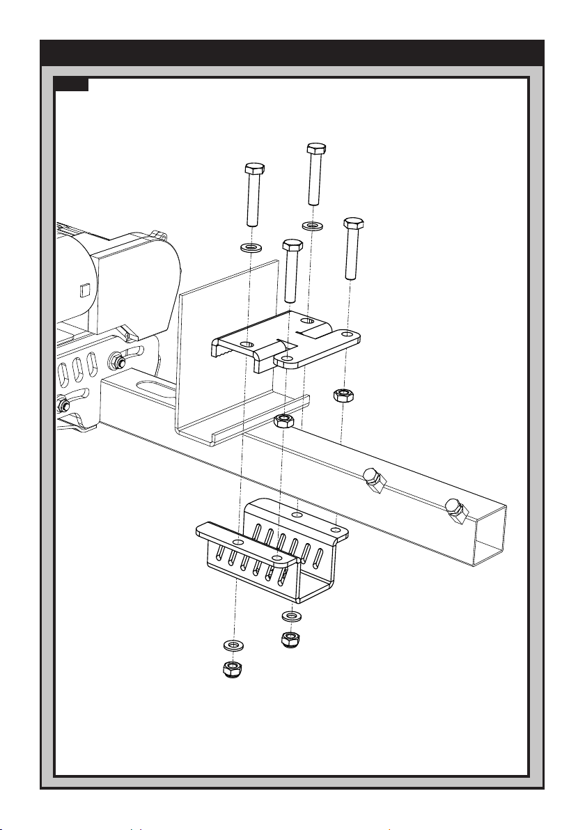
Typically the Shark Clamp will be pre-assembled onto the motorsides for ease of tting, but if the
clamps have been purchased separately or are not pre-assembled, they should be assembled onto
the framework as shown in (Fig.15). Before attempting to install the mover onto your caravan chassis
ensure that the fastening nuts (Fig.10.2E) are tightened, xing the rear bolts (Fig.10.2B) in place,
allowing the top jaw (Fig.10.2.C) to translate in the vertical axis.
With xing nuts and bolts loosely installed (Fig.10.2A and F), slide the top jaw (Fig.10.2C) up to open
the jaws of the clamp at one motorside. Hook the top jaw onto the caravan chassis, allowing the
motorside to hang in place. Repeat this process with the second motorside so that the full assembly is
suspended in place.
With the crossbar nuts/bolts loose (Fig.1B), adjust the lateral position of each motorside so that the
rollers are central to the tyre, or as close to the centre as possible, ensuring 10mm of space is left
between the tyre and gearbox for the Quattro Platinum (Fig.9). After adjusting ensure the clamps
haven’t moved out of position by holding the framework motorside rmly, while reaching round and
pushing the clamps outwards until the fastening bolts and chassis are within 1-2mm of each other.
Once happy with the overall width of the mover system, tighten crossbar nuts/bolts (Fig.1B) to
9ft lbs/12Nm to set the width.
Slide the whole assembly along the chassis until the rollers (Fig.2A or Fig.4A) are 20mm away from
the surface of the centre each tyre (Fig.5 or Fig.7). Two 20mm spacers (30) are provided. Fully tighten
the clamp bolts (Fig.10.2A) on both clamping assemblies to a torque setting of 40 ft lbs/55Nm. When
tightening one clamp bolt, the other may loosen slightly so it may take several passes to get both bolts
fully torqued on each clamp. A tip is to do all clamp bolts up until there is a strong resistance before
torquing fully.
Note that no tightening/torquing of the rear nuts/bolts (Fig.10.2B and E) is required. These
components are in place purely to assist with the installation process and are not a method of
afxation.
Installation - Quick-t Shark Clamp System (Fig.10.2)
Fully tighten the four nylock nuts (17) on both clamping assemblies (Fig.10.1) to a torque setting of 40
ft lbs/55Nm, then the four bolts (Fig.1B) on the Main Cross Bar (3) and the four bolts (Fig.1C) on Cross
Actuation assembly (4 & 5) to a torque setting of 9ft lbs/12Nm. Re-check the distance of 20mm from
the rollers to the tyres and if necessary, loosen the bolts and re-adjust the position of the assembly.
Once satised with the position of the assembly, t and tighten the Chassis Stop Nuts & Bolts (7) ,
one pair in each of the Upper Classic Clamp Plates (see Fig.10.1). Tighten to a torque setting of 40 ft
lbs/55Nm. The Stop Bolts grip the lip of the chassis and help prevent the mover from sliding along the
chassis. The main mechanical components have now been installed.

18 EN
Installation - Electrical/Electronic Components
Operation and Maintenance
Please refer to manual supplied with electronics for wiring installation, operation instructions
and troubleshooting.
Alternatively, for Smart Electonics visit www.purpleline.co.uk/qtr-m005
or for Basic Electronics visit www.purpleline.co.uk/qtr-m003
It is possible to position the caravan’s hitch exactly over a stationery car’s tow ball using the
mover. But please be very careful!
Hitch the caravan in the normal way ready for towing.
Release the rollers from the caravan’s tyres. You cannot tow the caravan with the Mover
engaged! Make sure that both rollers are fully disengaged!
Trying to drive away with the mover still engaged, will damage the mover, your caravan tyres
and strain your tow vehicle!
To prevent the battery from becoming totally discharged during long periods of inactivity it must be
disconnected and recharged before using again.
Please check regularly that the rollers of the drive units are free of any dirt, or debris that may have
been picked up from the road. Any further maintenance is not required.
Please check regularly the distance between the rollers and the tyres. In the neutral (fully disengaged)
position this must be 20mm.
When your caravan is stored for an extended period of time (over winter for example) it is
recommended to remove the leisure battery from the caravan. Make sure you keep it charged to
ensure it is in good condition the next time you want to use it.
Once a year have your caravan mover maintained and visually inspected. This inspection must include
all the bolt/nut connections, the cables and electrical connections and lubrication of movable parts/
joints.
In case of any failures or problems, please contact your Caravan Mover supplier.

19 EN
Product Registration
Please register your Quattro® caravan mover online within 14 days of purchase. Registration is quick
and simple, go to www.purpleline.co.uk/product-registration. Please retain your original purchase receipt.
Please ll-in the Serial Numbers + additional information and retain this manual for future
reference. The serial numbers can be found on the product label on each of the motor sections. The
serial number can be up to 18 digits long. Please make a note of your serial numbers in the section
below for future reference. The serial numbers will be required for product registration.
Motor Serial No.
Date of Purchase
Name of Dealer
Guarantee
Quattro®caravan mover systems are provided with a UK parts only warranty for a period of 7-years
which includes the rst 12 months statutory, plus an additional 6 years extended warranty. Please note
that the extended 6year warranty is only offered if Product Registration is completed and returned within
14 days from the date of purchase. Any warranty claims must be directed through the place of purchase
with a proof of purchase provided. Warranty cover is limited to products within UK mainland only.
Within the seven year period, the manufacturer will, at their sole discretion, replace or repair any parts
that have failed if deemed to be due to a manufacturing defect.
The manufacturer does not take responsibility for any consequential loss whatsoever.
Upon inspection, components that are missing when checked against the packing contents list must
be reported to the place of purchase within 5 working days.
This warranty cover is available only to the original purchaser of the product and is non-transferable.
What is not covered:
- Normal wear and tear.
- Damage that is deemed to be due to customer misuse or neglect.
- The cost of repair following accidental damage, abuse of product or deliberate tampering.
- Warranty is not offered for any type of trade or commercial usage.
- As a result of the recall or modication of all equipment in a model range.
- Force Majeure e.g. Damage caused by extraordinary events or circumstance beyond anyone’s control.
- Damage as a consequence of water ingress.
- Carriage or any additional charges incurred including travel or labour.
- Caravan electrics, including fuses, plugs, batteries, wiring connections and looms. Scratches, dents,
paintwork and cosmetic trim.
- Damage as a result of incorrect installation and/or disregard to manufacturers tting instructions.
- Cover will not be given to any part or component which is out of manufacture or no longer available.
- Cover will not be given if the product has been modied in any way.
- Damage occurring as a result of the product being used outside manufacturer’s load recommendations.

20 EN
Low Prole Chassis Adapter Plates (Part No. CM-029)
If your chassis frame height is less than 140mm these plates must be tted to lower the
assembly to provide the correct height of 185mm. Drilling of your chassis may be required.
Note: In some countries, the installation must be checked by a professional technician in order
to adhere to local regulations.
Narrow Gauge Chassis Adapters (Part No. CM-030)
These plates must be utilised if you have an AL-KO Vario III/AV chassis which has a frame
thickness of less than 2.8mm. These must be positioned behind the axle using pre-drilled holes
already available on the chassis; so your mover must be tted behind the axle.
16mm Spacers - 1 pair (Part No. CM-028/Q)
Use spacers to lower the mover assembly if your chassis has a frame height of between 140
to 185mm. A maximum of 3 sets of spacers can be utilised to achieve correct frame height of
185mm. A set of extended clamp bolts must be used in conjunction with these spacers (Part
No. CM-031).
[For use with Classic Clamp only.]
Set of 8 M10 x 100 Bolts (Part No. CM-031)
Set of 8 extended clamp bolts for use with 16mm spacers.
[For use with Classic Clamp only.]
Quattro500/600 Cover
(Part No. QTX10009 [LH] QTX10010 [RH])
Plastic cover for use in certain installations subject to further
technical requirements in Germany. If after installation the caravan
mover has easily accessible exposed sharp edges not covered by
the caravan bodywork, it is likely that this additional cover will need
to be installed.
Please contact Purple Line for further guidance and installation
detail.
EGO400/500 Cover
(Part No. QTX10006 [LH] QTX10007 [RH])
Plastic cover for use in certain installations subject to further
technical requirements in Germany. If after installation the caravan
mover has easily accessible exposed sharp edges not covered by
the caravan bodywork, it is likely that this additional cover will need
to be installed.
Please contact Purple Line for further guidance and installation
detail.
Additional chassis clamp adapters shown below are available for purchase:
Optional Fitting Adapters
This manual suits for next models
2
Table of contents
Languages:
Other Quattro Automobile Accessories manuals


Popular Automobile Accessories manuals by other brands


ULTIMATE SPEED
ULTIMATE SPEED 279746 Assembly and Safety Advice

SSV Works
SSV Works DF-F65 manual

ULTIMATE SPEED
ULTIMATE SPEED CARBON Assembly and Safety Advice

Witter
Witter F174 Fitting instructions

WeatherTech
WeatherTech No-Drill installation instructions

TAUBENREUTHER
TAUBENREUTHER 1-336050 Installation instruction