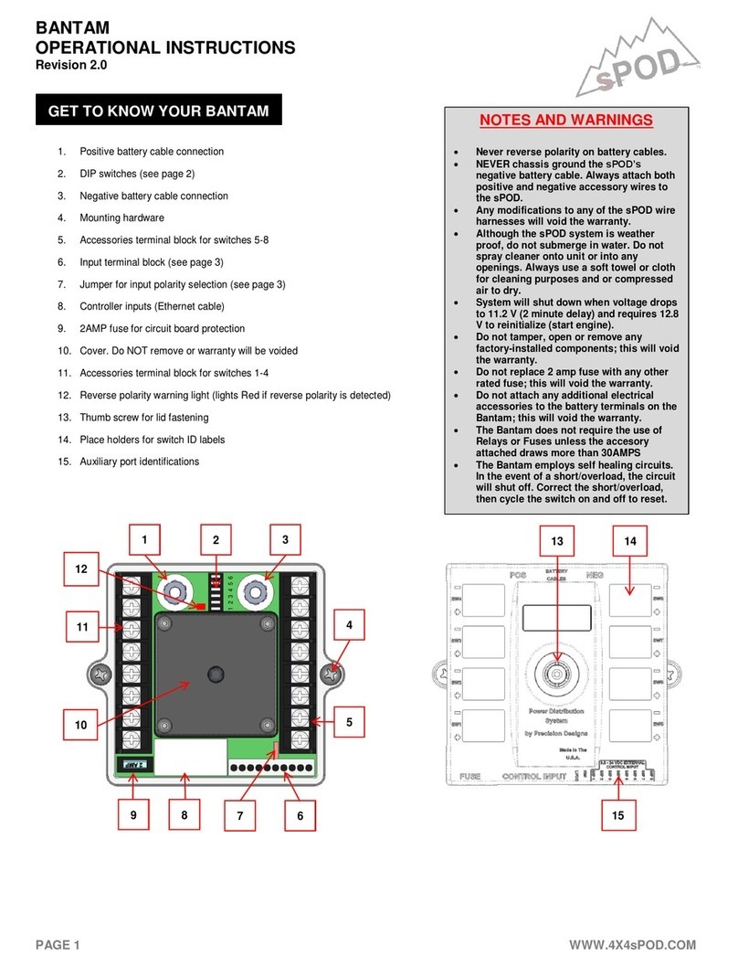
Spillard VCAS 200 User manual

Live Vision Detect Control
Vehicle Collision
Avoidance System
VCAS 200 Manual

2 3
Vehicle Collision Avoidance System | VCAS 200 Manual wspillard.com . einf[email protected] . t +44 (0)1902 797930
Contents
Vehicle Collision Avoidance System (VCAS) 4 - 5
Detection zone blind spot comparison 5
Product overview 6
Parts list 7
VCAS limitations 7
Active detection zones 8
Incorrect installation and alignment 8
Instructions 9
The sensor 9
Installation 10
Sensor removal 11
Daily test procedure 12 -13
Disclaimers and warnings 15
VCAS 200 Manual
Last revision July 2020
Spillard Safety Systems, Optronics and their respective logos
are registered trademarks of Spillard Safety Systems Ltd.
The entire content of this manual is copyright 2020 Spillard
Safety Systems. All rights reserved.

=0.5m
Area of detection at 1m high
4 5
Vehicle Collision Avoidance System | VCAS 200 Manual wspillard.com . einf[email protected] . t +44 (0)1902 797930
VCAS 200 Three sensor warning system
An industrialised object detection system monitoring to a
maximum of 4 metres from any sensor at any one time. When
mounted on a vehicle in a predetermined conguration, a 4 metre
primary sensing zone can be achieved, providing eective visual
and audible warnings to the vehicle’s operator, alerting them of
immediate dangers.
nPowerful non-contact sonic sensing technology -
max range = 6 metres.
nSpeech alert, 85db tone sounder and high intensity
LED warnings.
n‘Always on’ transparent operation, eliminates
operator interaction.
nLow maintenance – protected against dust, humidity
and air turbulence.
Vehicle Collision
Avoidance System
Dash Display
nHigh intensity status lights
- Object detected
n Audible warning - speech alarm
- Caution Object Detected
nIP68 Waterproof
VCAS 200 - a vehicle safety enhancement system
that warns operators of immediate dangers within
a predetermined range. The system provides the
assurance of safety when a site dumper’s operation
commences, and cannot be turned o or ignored by
operators unfamiliar with its features.
Detection zone blind
spot comparison

12vDC
sensor
1
sensor
2
sensor
3
SPILLARD
safety system s
6Vehicle Collision Avoidance System | VCAS 200 Manual 7
wspillard.com .einf[email protected] . t +44 (0)1902 797930
VCAS limitations
VCAS is an aid to safety, and should be used in addition to your safe system of work.
n The operator should be aware of the benets and limitations of this system. The daily check
procedure must be followed to determine the operation state of the system before starting
their daily shift.
nAll sensors will not work if an obstruction is covering the sensing face e.g. mud or concrete.
n Sensors detect 4 metres in front of the vehicle. The area covered is dependent upon the
mounting position/angle of each sensor. Dead zones may be created due to sensing shape.
nThe response times from sensors and the operator are reduced when speed is increased.
nDamage to a sensor will start to deteriorate the sensing capabilities of the system.
nThe speaker will not be heard if obstructed or covered.
nAll faults or damage must be reported immediately.
Parts list
1 x VCB205- Display
3 x BVC307- Sensor Housing
+ VMS602Sensor
1 x VFY222 - Cable Assembly
1 x 24mm Grommet
2 x M6 x 15mm set screws
6 x M6 x 25 mm set screws
6 x M6 Nyloc Nuts
12 x M6 washers
1 x 2 amp auto fuse and holder
Smooth sloping surface Sound absorbing material
Smooth round object High/low objects
Product overview Parts & Limitations

8 9
Vehicle Collision Avoidance System | VCAS 200 Manual wspillard.com . einf[email protected] . t +44 (0)1902 797930
Active detection zones Instructions
Incorrect installation and alignment
High accuracy round bar Ø27mm
Low accuracy at plate 500mm x 500mm parallel with sensor
Display
The display must be mounted in front of the operator, facing
towards them. When detection is made, the red light on the display
will illuminate and “caution, object detected” will be sounded.
n Connect the main loom cable to the display and run the main
loom cable along the chassis to the front of the machine.
Connect the cables from the sensors to the 3 way block and
apply the heat shrink.
n Connect the power cable blue wire to a suitable earth and
brown positive wire to fuse holder, and then to an ignition
feed.
n Bolt the display to the top of the steering column/
dashboard.
The sensors
The sensors are pre-installed in a protective housing suitable
for your application.
“The display must be mounted in front
of the operator, facing towards them.”

Minimum 400mm800mm
4000mm
10 11
Vehicle Collision Avoidance System | VCAS 200 Manual wspillard.com . einf[email protected] . t +44 (0)1902 797930
Installation
The 3 Sensors are to be mounted onto the front of the dumper at
even distances apart, to create a forward-facing detection zone.
The sensors are adjustable to ensure no detection is made with
raised iron works or objects wider than the machine.
Sensor removal
If the sensor is to be removed or replaced, to ensure the sensor is
mounted in the correct position within the housing, please follow
the image guidance below.
Mounting
Mount the hanging brackets to the chassis of the machine with the
centre of the brackets 800mm from ground level. (Fig.2)
nThe centre bracket must be mounted in the centre of the
vehicle and will only be adjusted on the vertical plane.
nThe outer brackets should be mounted as wide as possible.
Attach and adjust
Attach the sensor housing to the outer
bracket.
Adjust the top bolt for Left Right toe in to
stop detecting wider than the machine.
(fig.1) (fig.4)
Adjust the rear bolt to angle the sensor face
upwards slightly to detect approx 400mm
off the ground @ 4 metres (fig.3)
IMPORTANT
The sensor cable must only be nger tightened to the sensor and cable tied to the
bracket once looped back with a minimum bend radius of 25mm.

12 13
Vehicle Collision Avoidance System | VCAS 200 Manual wspillard.com . einf[email protected] . t +44 (0)1902 797930
Daily test procedure
Dashboard
1. Place a cone or similar object at the position, approximately 2 metres away
from the front of the skip.
2. Turn the dump truck ignition on - DO NOT START.
3. Ensure the red light is illuminated and the speech alarm can be heard.
Sensors
Leaving the ignition on and NOT STARTED, remove the cone.
Standing at position 2, hold the test target in front of the rst sensor, then hold the
target in front of the second sensor. Repeat the steps standing in position 3, ensuring
there is an audible alert from all sensors.
2
2
3
1
2 3
1
m
Ensure there’s an
audible alert from
ALL SENSORS.

14 15
Vehicle Collision Avoidance System | VCAS 200 Manual wspillard.com . einf[email protected] . t +44 (0)1902 797930
Disclaimers and warnings
A smart construction site
is a safe construction site.
This manual contains important information required for the proper installation of the Spillard Safety
Systems equipment. Please read the manual thoroughly before installation and/or operation of the system.
Spillard Safety Systems cannot assume responsibility for the improper installation of the system.
Although Spillard Safety Systems exercises all reasonable eorts to ensure its products perform properly in
aftermarket and OEM applications, Spillard Safety Systems assumes no responsibility for deciencies in their
installation. It is the installer’s responsibility to consider and avoid possibly hazardous conditions that could result
from the installation of the system. It is the responsibility of the installer to carry out the installation in accordance
with recommended practices outlined in this manual. Spillard Safety Systems cannot assume responsibility for
installations that are performed by end customers or dealers.
Spillard Safety Systems cannot assume responsibility for either the training of operators or for their proper use of this
system. It is the responsibility of the end users to ensure all operators are fully trained regarding the proper use of
the system.
Avoidance of hazards
The suggestions provided in this guide regarding avoidance of
hazardous conditions apply to all applications and are necessarily of
general nature since only the installer is familiar with the details of
his/her installation. The suggestions provided in this guide should
be considered general examples only and are in no way intended
to cover every possible hazard in every installation.
Improper operation, maintenance or repair of this product can
be dangerous and could result in injury or death. Do not operate
or perform any maintenance or repair on this product, until you
have read and understood the operation, maintenance and repair
information.
Most accidents that involve product operation, maintenance
and repair are caused by failure to observe basic safety rules or
precautions. An accident can often be avoided by recognising
potentially hazardous situations before an accident occurs. A
person must be alert to potential hazards. This person should
also have the necessary training, skills and tools to perform these
functions properly.
NOTE:
Spillard Safety Systems cannot anticipate every possible
circumstance that might involve a potential hazard. The warnings in
this publication and on the product are, therefore, not all-inclusive.
If a tool, procedure, work method or operating technique that is not
specically recommended by Spillard Safety Systems is used, you
must satisfy yourself that it is safe for you and for others. You should
also ensure that the product will not be damaged or be made
unsafe by the operation, maintenance or repair procedures that you
choose.
The information, specications, and illustrations in this publication
are on the basis of information that was available at the time
that the publication was written. The specications, adjustments,
illustrations, and other items can change at any time. These
changes can aect the service that is given to the product.
Obtain the complete and most current information before you
start any job. Consult Spillard Safety Systems for the most current
information available.
When replacement parts are required for this product, Spillard
Safety Systems recommends using its own replacement parts or
parts with equivalent specications including, but not limited to,
physical dimensions, type, strength and material. Failure to heed
this warning can lead to premature failures, product damage,
personal injury or death.
Installation precautions
Spillard Safety Systems recommends the system should only be
installed by a competent person.
Spillard Safety Systems recommends the installer seeks advice
from the machine manufacturer before commencing installation,
specically in regard to all electrical connections.
Each system installation might have unique safety considerations
that may or may not relate to items addressed in this document.
Installers should use this and all other resources that may be
relevant to their particular application to determine whether all
reasonably foreseeable hazards have been adequately addressed.
The system should be installed in compliance with any applicable
standards for the application.
Spillard Safety Systems shall not be liable to the buyer for any loss
which may be suered by the buyer should the system fail. The
buyer’s attention is specically drawn to the limitations on liability
contained within clauses 6 and 7 within our Standard Terms and
Conditions of Sale. Copy available on request or at
www.spillard.com/terms
Applies to seat belt:
THE ROLL OVER PROTECTION STRUCTURE (ROPS)
MUST NOT BE DRILLED.
The lap belt should only be used in conjunction with the suggested
electronic buckle. Even if the belt may appear to lock into another
buckle, it may fail in the event of an incident.
Operational precautions*
The system is designed to supplement the machine’s safety during
its operation
*Prior to operating the machine, always conrm the system is operating correctly by using the daily test procedure provided.

Vehicle Collision
Avoidance System
Mining Public Transport Refuse Light GoodsHeavy GoodsConstruction
Mobile safety solutions
that increase awareness
and reduce incidents
Spillard Safety Systems Ltd, Solutions House, Station Road, Four Ashes, Wolverhampton, WV10 7DB
Table of contents

