Hyundai H5699100 User manual

Universal Park Distance Aid System Installation Instructions issue 1.0 – 01/12/03
Park Distance Aid Part No. H5699100
Prior to installation carry out a pre installation inspection
check.
•Interior/Exterior condition
•Electrical ancillary equipment operation
•Battery disconnection prior to commencing the
installation and note any security codes.
•This system REQUIRES SET UP following
installation (See page 5)
KIT CONTENTS
OPERATION
The PARK DISTANCE AID is activated automatically
when reverse gear is selected. The sensor eyes emit an
acoustic field around the rear of the vehicle. The system
then evaluates the waveforms and calculates the
distance from objects around the bumper area; these
signals are in turn converted instantly to an audible
beeper hidden within the vehicle.
Diagram 1.
•The system beeps once when an obstacle is
between 200cm & 120cm away, safety zone)
•A repeated beeping begins when an obstacle
is between 120cm & 30cm away and
increases in frequency as the obstacle
becomes closer Alert zone)
•A constant beep is emitted when the vehicle
enters the maximum alert zone) between
30cm & 0 from an obstacle.
KEY POINTS OF THE INSTALLATION
A. Prior to routing the sensor leads ensure the white
“identification collar tabs” around the sensor leads
are secured in position with insulation tape. This
will prevent the collars being trapped behind
grommets etc during routing. Each lead is
numbered and will require identification when
connecting to the numbered ports on the ECU.
B. NOTE: The two inner sensor leads 2 & 3) are 2
metres in length and the two outer sensor leads
1 & 4) are 2.5 metres in length.
C. The leads to each sensor eye must be run in
numerical order 1,2,3 & 4 across the bumper from
left to right.
D. Ensure that the small spot on the front of each
sensor eye is located at the top.
E. Do not apply tension to the leads during routing, as
this may result in disengagement and possible
damage to the sensor eye.
F. Should the sensor eyes require spraying to body
colour, please refer to the section “Spraying The
Sensor Eyes” at the rear of this manual.
G. Ensure that the holes drilled to accommodate the
sensor eyes are exactly 20mm Ø and there is at
least 23mm depth.
H. Following installation, carry out the “System Set up
Procedure” on Pg 5. NOTE: In the event the
system does not set up satisfactorily, reconnect the
two Blue wires from the ECU back together again
and carry out the system set up again. Ensure the
vehicle is parallel with the wall and 50cm away.
I. During System Set up, avoid walls with drainpipes
or other surface objects that may adversely
influence set up.
J. When deciding the mounting position of the ECU,
ensure it is within reach of the shortest sensor lead.
K. The set up procedure must be repeated if one of
the sensor eyes is replaced.
L. To avoid faulty operation, snow, ice, and dirt must
be cleaned from the sensor eye.
M. In certain circumstances, low or very thin obstacles
may not be detected. Also undulations in the
ground may give rise to sporadic detection
patterns.
N. For information concerning the minimum and
maximum distances permissible between sensors,
refer to diagrams 1 8
Document Part No: MKHYUUNI1203
1
NB. If it is not possible to maintain the dimensional protocol as shown in diagrams 1 – 7, contact the help-line on Pg 5
PARK DISTANCE AID – Universal Installation Manual

Universal Park Distance Aid System Installation Instructions issue 1.0 – 01/12/03
When installing on particularly wide vehicles do not
exceed the recommended maximum overall width of
1600mm from each outer sensor eye.
Diagram 1.
When installing on particularly narrow vehicles do not
go below the critical minimum overall width of 900mm
from each outer sensor eye.
Diagram 2.
Always observe the recommended (ideal) sensor
locations points as indicated in diagram 3A. Try to
maintain a straight horizontal line across the bumper.
Example
Diagram 3.
The sensors ideally should be mounted between
450mm & 550mm from the ground.
Diagram 4.
The outer sensors ideally should be mounted at least
150mm from the extreme edge of the vehicle.
Diagram 5.
If the sensor eyes require staggering due to mouldings
within the bumper or number plates, spare wheels etc,
do not exceed a 100mm drop or rise.
Diagram 6.
Should the inner sensor eyes require a wider width than
the outer sensor eyes due to number plates etc, do not
exceed a gap of 700mm between the 2 inner sensors
2 & 3. As a result of the wide inner width, try to maintain
a gap of (Ideally) of 300mm or up to 450mm between
sensors 1 &2 / 2 & 3
Document Part No: MKHYUUNI1203
2
550mm
450mm
100mm
1/8
1/4
1/4
1/4
1/8
1/2
1/2
150mm
300mm
Minimum
300mm
Minimum
700mm
Maximum
Maximum Overall Width
1600mm
Minimum Overall Width
900mm
194
388
388
388
194
776
776
1552mm
Overall Width
A
B

Universal Park Distance Aid System Installation Instructions issue 1.0 – 01/12/03
Diagram 7.
The coverage of the sensor is dependent on the height
and angle of the sensor from the ground. If the sensor
is pointing down or mounted to low on the bumper, the
system may suffer from “Ground Affect”, (Reflection
from undulations in the ground) or “Erratic Detection”.
Angled Spacer sleeve
Diagram 8.
GENERAL
Divide the total width of the vehicle as shown in
diagram 9.
Diagram 9.
These measurements are the optimum position for the
sensors. Observe the spacing measurements between
the sensors whenever possible, however sometimes
the contours and features of the of the bumper
moulding etc can dictate particular mounting points.
See Diagrams 1 8
Check for protrusions at the rear of the vehicle e.g. Tow
Bars, overhanging bumpers etc. If these items are in
the sensors 60o cone detection area the system will not
operate correctly, therefore allowances should be made
and the installation positions vary accordingly.
When determining the dimensional position of the
sensors, ensure the vehicle is at its normal ride height.
DRILLING THE HOLES
Ensure that there is at least 23mm depth directly behind
the sensor eye prior to drilling.
NOTE: Some vehicles have foam protection directly
behind the bumper, this foam can cause cone cut tools
to drift during drilling and elongate the hole. It is
recommended a 20mm Ø hole saw & arbor is used to
drill all holes.
Identify a panel that is flat and vertical to the ground at
the rear of the vehicle for the sensors to be mounted.
This position ideally should be no less than 450mm and
no higher than 550mm from the ground. (The vehicles
bumper is normally the ideal position).
Try to establish a flat surface for the sensor eyes as
excessive curves will separate from the sensor lip edge.
Apply the template stickers exactly in poison and
ensure that any lines drawn on the bumper are done so
using a marker that can be wiped away without trace.
Always take additional measurements from fixed
moulding points on the vehicles bumper and not items
such as number plates as the location may not be
symmetrical.
Should an inner skin or panel be directly behind the
mounting hole, caution should be taken prior to drilling.
If you are unsure of any aspect of the installation,
remove the bumper and investigate. Do not drill steel
reinforcement members.
When the position of each sensor is determined; Drill a
2mm Ø pilot hole through the bumper moulding at the 4
location points.
Open out the 4 holes to exactly 20mm Ø using a
holesaw & arbor see diagram 10. Alternatively a
stepped cutter may be used however, never use a
stepped cutter when drilling bumpers with foam support
to the rear as this will cause the stepped cutter to drift &
elongate the hole.
Document Part No: MKHYUUNI1203
3
Requires
Angled
Spacer
Standard Sensor eye.
From 0° – 5° maximum.
NOTE: as the angle
increases the mounting
height from the ground
must increase
retrospectively
15° Spacer sleeve must be
used on all sensors mounted
with 5° 15° angle.
NOTE: 15° maximum angle
550mm
1/8
1/4
1/4
1/4
1/8
1/2
1/2

Universal Park Distance Aid System Installation Instructions issue 1.0 – 01/12/03
Diagram 10.
Often, when using hole saws, it is possible to continue
to cut out any foam support directly behind the bumper
to accommodate the sensor eye, however, take care
not to cut any cable or any other obstacle that may be
in the way.
Using a small file cut a small keyway in the top of the
20mm Ø diameter hole to accommodate the locating tab
on the top rear of the sensor pod
Diagram 11
This will ensure the small spot at the top front of the
sensor eye is located at the top.
Remove any foam directly behind the sensor eye and
just under the rear of the sensor location so as to
accommodate the connector, which protrudes down
and away from the rear of the eye.
CONNECTING THE SENSOR EYE LEADS
Insert the numbered lead of each sensor through their
respective holes, numbered 1 – 4 (1=Outer Left,
4=Outer Right).
Connect the sensor leads to the rear of the sensors
eyes, ensure the connectors click into place, and fit the
rubber sealing boots.
Insert the sensor into the bumper, (it should locate in
position with a little pressure) and verify the rear
locating tab and front spot is at the top.
SENSOR CABLE ROUTE
NOTE: Each of the sensor leads have numbers on
small white identification tabs located around the sensor
collar, it is essential each lead are allocated the correct
location point in the Park Distance Aid ECU (See
Diagram 12.) Taping the identifying number tabs to the
lead will assist when routing the leads through.
Try to use an existing grommet such as the number
plate light grommet when routing the leads.
Secure the leads at regular intervals within the bumper
chamber using cable ties. Ensure a small coil of cable is
left within the bumper chamber in order to facilitate any
future removal of the bumper at a later date.
MOUNTING THE BUZZER
Mount the buzzer (using the adhesive pad provided) on
a flat horizontal surface if possible. Ensure the buzzer is
clearly audible to the driver when the engine is running.
Route the lead through to the main ECU and connect in
place. Cable tie any surplus wire in position.
NOTE: Heating the adhesive pad and corresponding
mounting panel with a hot air gun will increase the
adhesive bonding process.
ELECTRICAL CONNECTIONS
Diagram 12.
FIXING THE ECU BLACK GROUND WIRE
The Black Ground wire from the ECU is equipped with a
ground ring terminal. Try to utilize existing ground
points whenever possible or a nut or bolt on the bulk
panels.
Avoid using the mounting nuts & bolts holding the light
assemblies in place, these are often mounted through
Document Part No: MKHYUUNI1203
4
Cut a small
keyway with a
triangular file
20mm Ø
Blue Loop Wire
Set-Up
ECU
Buzzer
4xNumbered
Sensor Eye
Ports
Black Wire
Ground
4xSensor
Eyes
4xNumbered
Sensor Leads
Red Wire
Reverse
Light
Supply

Universal Park Distance Aid System Installation Instructions issue 1.0 – 01/12/03
rubber sleeves and consequently provide poor ground
points.
If no suitable ground point is available use the ground to
the rear light assembly.
FIXING THE ECU RED LIVE WIRE
Cut the Red wire from the ECU to length and splice in
place to the reversing light switched 12v positive. (Wire
that becomes live when reverse gear is selected)
located at the light assembly.
Splice/solder in position and protect the soldered joint.
NOTE: Use a metre or test light to verify the reverse
light switched positive is correct prior to connection.
MOUNTING THE ECU
Identify a mounting point inside the vehicles boot area
behind a panel, near the sensor leads entry point and
reverse light connection.
Mount in position (horizontally if possible) using the
adhesive pad provided.
SET-UP PROCEDURE
Confirm all electrical connections are correct prior to
reconnecting the battery terminal.
1. Position the rear bumper of the vehicle,
parallel, exactly 50cm from a wall.
2. Turn the ignition on and select reverse gear.
(Do not turn the engine over)
3. A DOUBLE TONE will be emitted followed
within 100 seconds (evaluation time) by a
single CONSTANT tone. N TE: If a single
intermittent tone is emitted at this point, (or no
tone at all) during the 100-second evaluation
time, the set-up has not been successful and
must be repeated. Refer to pages 6 “ ystem
set-up & fault diagnosis”
4. Following the constant tone, turn the ignition
off and cut the blue loop wire on the harness
going into the ECU.
5. The system is now “Set up”
Insulate the two cut ends of the blue loop wire and
secure to the harness.
CUSTOMER HANDOVER
Ensure a responsible member of staff fully explains the
operation of the Park Distance Aid System and provides
the customer with the user instructions.
SPRAYING THE SENSOR EYES OPTION)
The sensors inner transducer eye itself is made from
Aluminium (Pre Coated) while the outer sensor sleeve
ring is made from "PBT" / Valox material.
The plastic masking rings must be put over the central
silicon absorber before painting. The reason for this is
to prevent paint coating this part, as it would reduce the
vibration capability of the transducer itself.
Insert the 4 sensor eyes in the cardboard spraying try
provided, and place on a flat horizontal surface. Protect
the table or bench surface around the tray.
Insert the spacer rings provided securely in position.
It is important to apply the spray in even thin coats from
various angles approximately 300mm from the sensors.
Use more than one coat if required, applying too much
spray at one time will form ripples or gather to one
edge.
1. Apply an appropriate primer spray to each
sensor. And immediately REMOVE THE
MASKING RINGS. NOTE: If the masking rings
are removed when the paint is dry, it will
fracture the paint surface around the silicon
band.
2. Allow 20minitues to dry
3. Apply the paint following the details described
above, Remember to use thin even strokes
and more than one coat with an appropriate
drying period between coats.
4. Once again REMOVE THE MASKING RINGS
whilst the paint is still wet to prevent cracking.
5. Depending on the type of vehicle body paint, it
may be necessary to apply a lacquer to the
surface paint.
Document Part No: MKHYUUNI1203
5
Table of contents
Other Hyundai Automobile Electronic manuals
Popular Automobile Electronic manuals by other brands

DRG
DRG LC 120 installation instructions

Blue Ox
Blue Ox BX8848 installation instructions
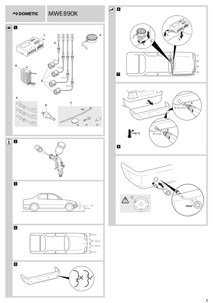
Dometic
Dometic MAGICWATCH MWE890K Installation and operating manual
Honeywell
Honeywell Thor VM3A user guide

Waeco
Waeco MagicWatch MWE250 Installation and operating manual
GoldCruise
GoldCruise GC90Ci installation manual

