FAAC GRS-02 User manual

C E DECLARATION OF C O N F O R M I T Y
Manufacturer:
FAAC
S.p.A
.
Address:
Via Benini,
1
40069 - Zola
P
r
edosa
BOLOGNA -
IT
A
L
Y
Declares that
:
Token acceptor
GRS-02
•
conforms to the essential safety requirements
of the
following EEC directives
:
73/23
EEC and following modification
93/68/
EEC
89/336
EEC and following modification
92/31
EEC and
93/68/EEC
Additional notes:
this product underwent tests in a typical
homogeneous
configuration
(all products by FAAC
S.p.A
.).
Bologna,
2nd January
2009
The Managing
Director
A.
Mar
cellan
1

GENERAL SAFETY OBLIGATIONS
1) ATTENTION! To ensure the safety of people, it is important that you read all the following
instructions. Incorrect installation or incorrect use of the product could cause serious harm to
people.
2) Carefully read the instructions before beginning to install the product.
3) Do not leave packing materials (plastic, polystyrene, etc.) within reach of children as such materials are potential
sources of danger.
4) Store these instructions for future reference.
5) This product was designed and built strictly for the use indicated in this documentation. Any other use, not expressly
indicated here, could compromise the good condition of the product and/or be a source of danger.
6) FAAC declines all liability caused by improper use or use other than that for which the product was intended.
7) Do not install the equipment in an explosive atmosphere: the presence of gas or inflammable fumes is a serious danger
to safety.
8) FAAC is not responsible for failure to observe Good Technique in the installation of the product.
9) Before attempting any job on the system, cut out electrical power.
10) Make sure that a differential switch with threshold of 0.03A is fitted upstream of the system.
11) Make sure that the earthing system is perfectly realised and connect the yellow/green earth terminal of the Token
Acceptor to it.
12) FAAC declines all liability as concerns safety and efficient operation of the Token Acceptor, if system components
not produced by FAAC are used.
13) For maintenance, strictly use original parts by FAAC.
14) Do not in any way modify the components of the Token Acceptor.
15) The installer shall supply all information concerning the system operation and shall hand over to the user the “User’s
Guide” supplied with the product.
16) The user must not attempt any kind of repair or direct action whatever and contact qualified personnel only.
17) Anything not expressly specified in these instructions is not permitted.
2
ENGLISH
ENGLISH

TOKEN ACCEPTOR GRS-02
The GRS-02 Token Acceptor consists of a steel upright with
cataphoresis treatment and polyester painting. The upright
houses the FAAC token accepting module and the collection
tray. The Token Acceptor is prepared for the application of a
DIN guide on which a Detector can be installed to enable the
token insertion only in the presence of a vehicle.
The GRS-02 Token Acceptor was designed and built to
control pedestrian or vehicle accesses.
Avoid any other use.
1. DESCRIPTION AND TECHNICAL
SPECIFICATIONS
The GRS-02 Token Acceptor is a pulse generator that, when a
token is inserted, controls the opening of pedestrian or vehicle
accesses.
In the “pedestrian” configuration, the token insertion slot must
be always open (in this case, the shutter must be physically
removed).
In the “vehicle” configuration, by interfacing a Single- or a
Two-Channel Detector, you can enable the token insertion only
in the presence of a vehicle; in this case pedestrians are not
allowed to use the lane.
Tab.1 Technical Specifications GRS-02 Token Acceptor
2. DIMENSIONS
fig.2
3
POWER SUPPLY
MAX. ABSORBED POWER
OPERATING AMBIENT
TEMPERATURE
WEIGHT
HOUSING PROTECTIVE
TREATMENT
HOUSING PAINT
No. CONTACTS
TOKEN CONTAINER CAPACITY
OVERALL DIMENSIONS
24vdc (solo gli accessori)
SEE INDIVIDUAL ACCESSORIES
CATAPHORESIS
Opaque Grey and Blue Micalised Polyester
-20°C / +50°C
14 KG
2 (N.O. or N.C.)
APPROX. 2000 PCS.
SEE FIG. 2
Token accepting module
Facility for DIN guide
Door with lock
Token collection tray
Token insertion slot
24VDC (ACCESSORIES ONLY)
ENGLISH
ENGLISH

ENGLISH
3. ELECTRIC PREPARATIONS
3.1. PEDESTRIAN ACCESS
If the Token Acceptor is used to control the opening of a
pedestrian access you need to remove the shutter from the
token acceptor:
Prepare a 2 x 1 mm² cable between the token acceptor and the
control unit of the gate or barrier.
3.2. VEHICLE ACCESS IN LOGIC “A”
If you need to control the opening of a vehicle access only,
without having to control a beam closing contact, operate as
follows:
•add a Single-Channel Detector FG1 (to connect the use of
the Token Acceptor according to the presence of a
vehicle)
•realise a magnetic loop
•provide 24 Vdc –500 mA power supply
•perform the electric preparations as shown in fig.3
3.3. VEHICLE ACCESS IN LOGIC “P”
If the GRS-02 Token Acceptor is used to control a vehicle
access and simultaneously manage the beam closure, you
need to perform the following:
• add the Two-Channel Detector FG2 (to connect the use of
the Token Acceptor according to the presence of a vehicle
and control the beam closure)
• realise two magnetic loops
• provide 24 Vdc - 500 mA power supply
• perform the electric preparations as shown in fig.4
4. INSTALLATION
4.1. PRELIMINARY CHECKS
To ensure safety and an efficiently operating Token Acceptor,
make sure the following conditions are observed:
•The soil must permit sufficient stability of the foundation
plinth.
•There must be no pipes or electrical cables in the plinth
excavation and in the loop areas.
•If the Token Acceptor is exposed to passing vehicles,
install, if possible, adequate means of protections against
accidental impact.
•Check that an efficient earth socket is available for
connecting the housing of the Token Acceptor.
4.2. POSITIONING THE COMPONENTS
4.2.1. PEDESTRIAN ACCESS
Before placing the foundation plate of the GRS-02 Token
Acceptor, make sure the following conditions are observed:
•The Token Acceptor must be installed in such a way not to
expose the user to impact, crushing, dragging risks etc.
due to the movement of the gate or barrier.
4.2.2. VEHICLE ACCESS
Before placing the foundation plate of the GRS-02 Token
Acceptor, make sure the following conditions are observed:
•The Token Acceptor must be installed in such a way not to
expose vehicles to impact, crushing, dragging risks etc.
due to the movement of the gate or barrier
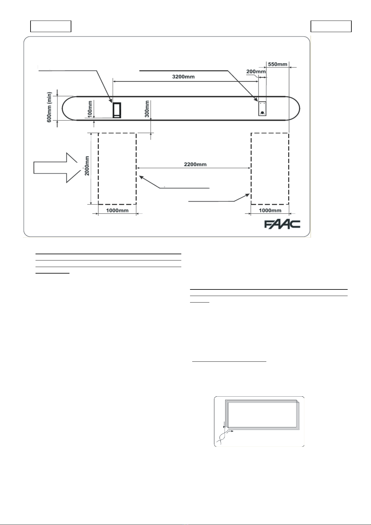
•Place the Token Acceptor in such a way that the vehicles
coming from various directions can approach the Token
Acceptor enabling the driver to insert the token without any
difficulties.
•Realise the magnetic loop in correspondence with the
Token Acceptor (the loop must be engaged by the vehicle
when the window is in front of the token insertion slot). The
loop must be dimensioned according to the type of vehicle
to detect: observe the dimensions given in fig.5 for
vehicles and vans or the dimensions in fig.7 to detect
heavy vehicles. To realise the loop follow the instructions
in Chapters 4.3. and 4.4.1.
4
Token Acceptor GRS-02 + shutter
+ two-channel detector FG2
1 - Barrier 620
2 –Magnetic loop (see chpt. 4.3.)
3 -Miniservice power pack
To TD 620
1) Token Acceptor GRS-02 +
Single-Channel Detector
FG1
2) Access to control
3) Miniservice power pack
4) Magnetic loop (see chapter
4.3.)
ENGLISH

•The magnetic loops must be positioned as shown in fig. 5:
only if positioned in this configuration, the loops are able to
manage the vehicle count in a correct way and to control
the re-closure of the barrier exclusively after the vehicle
has transited. However the dimensions can be adapted to
the lane width and to the type of vehicles to detect: fig.5
shows the loops to be used in the event of a lane width of
2.5 m for cars and vans.
•The Token Acceptor and the Barrier must be installed on
an island lifted by approx. 15 cm. with respect to the
street surface in order to protect them against impacts
during vehicle movement. If this is not possible, install
suitable protective structures around the base of both
housings.
.
4.3. REALIZING THE MAGNETIC LOOPS
The magnetic loops can be realised in two different ways:
laying the cable directly in a chase made in the existing
pavement or, this is the best solution, realising a cable duct in
PVC before the pavement is made.
In both cases, the cable must be laid not over 5 cm from the
surface and not less than 15 cm from covers or other metallic
objects.
In case of a cable duct, you can use a normal single-pole cable
with 1.5 mm² section. On the contrary, the cable directly laid in
the chase must have the same section but with double
insulation (for the realisation of the chase, see chapter 4.4.1.).
The loop must be realised with a single cable without making
any joints. Both ends of the cable must be twisted each other
(at least 20 times per meter) for the whole section from the
loop to the Detector terminal board.
The number of windings of the loops is 4.
5
POSITIONING LAYOUT OF ENTRY/EXIT LANE DEVICES
Foundation plate for Token
Acceptor GRS-02
Foundation plate for Barrier 620 rapid
(RH version)
Sense of direction
Presence loop
Transit loop
Loop made of 4
windings
ENGLISH
ENGLISH

4.4. MASONRY PREPARATIONS
4.4.1. CHASE FOR THE MAGNETIC LOOP
Fig.8 shows the realization of the magnetic loop chase. The
corners must be cut at 45°, as shown in the figure, to prevent
the cable breaking in the corners. After the cable has been
laid, the chase must be sealed with bitumen.
Realize the case at a distance of at least 15 cm. from metallic
objects (pits, grids, etc.).
If the pavement is still to be made, prepare a cable duct (if
possible with a plastic duct in one of the loop corners) and
calculate its depth according to the thickness of the finished
pavement (when pavement jobs are finished, the loop must
be at a distance greater than 5 cm from the surface).
4.4.2. MASONRY OF THE FOUNDATION PLATE
1) Assemble the foundation plate as shown in fig.9.
2) Make a foundation plinth as shown in fig.10 and wall the
foundation plate supplying one or more sheaths for
routing electrical cables. Using a spirit level, check if the
plate is perfectly level. Wait for the cement to set.
fig.10
3) Prepare the electric cables for the connection as indicated
in Chapter 3.1, 3.2 or 3.3 according to the type of use. For
easy connection, let the cables come out of the foundation
plate hole for approx 1m. .
4.5. FASTENING
Make sure that the foundation plate is correctly secured and
that the cement has set. Unscrew the plate nuts and fasten the
Token Acceptor routing the cables from the inner part of the
base to the door.
5. ELECTRICAL CONNECTIONS
5.1. PEDESTRIAN ACCESS
In the configuration for pedestrian access management there is
a microswitch with 2 potential-free contacts, N.O. and N.C., to
send the Open command to an automated system.
The terminals are positioned as shown in fig.11.
fig.9
6
Dimensions in mm.
N.C. contact
N.O. contact
Common contact
ENGLISH
ENGLISH

ENGLISH
5.2. VEHICLE ACCESS IN LOGIC “A”
In the configuration for the management of a lane in logic “A” you
need to add a detector FG1. Fasten the DIN guide on the two
available screws and press the detector in place.
Prepare a 24 Vdc power supply and perform the connections as
shown in fig.13.
Presence Time and Reset
The presence time can be set
using the
microswitch
“h”. At the end of the
presence time the detector
signals “loop free” and self-calibrates. The presence time starts
when the loop is engaged. An automatic reset is performed
when the detector is activated or when the dip
“h” setting changes.
Operation of the Relay
The detector is equipped with 2 relays:
Relay 1 supplies a presence
contact, while Relay 2 sends a pulse
when the loop is disengaged. The operation of
Relay 1 can be selected by changing the setting of the
dip “r”.
N.B.: For this application you need to select the operation
“N.O.” contact.
Frequency selection
The detector operating frequency
can be set on
two levels according to the position
of the loop connector.
Frequency depends furthermore
on the loop shape, on the
number of windings and on the cable total length.
N.B.: For any further explanations on the operation of the
detector FG1, please refer to the specific instructions of
the product.
5.3. VEHICLE ACCESS IN LOGIC “P”
In the configuration for the management of a lane in logic “P”
you need to add the detector FG2. Fasten the DIN guide on the
two available screws and press the detector base in place.
fig.13:
the token insertion slot only opens when a vehicle is on the
magnetic loop. The gate or beam opening command must be
connected to the microswitch of the accepting module (see
Chapter. 5.1.).
For the detector FG1 programming, operate as follows:
Sensitivity
The detector sensitivity can
be set on four
different levels using the two first
microswitches on top
(close to letter s).
7
loop
PRESENCE TIME
5 minutes
SENSITIVITY
LOW
MEDIUM-LOW
MEDIUM-HIGH
HIGH
RELAY 1 FUNCTION
N.C. CONTACT
N.O. CONTACT
FREQUENCY
LOOP CONN.
LOW
LOOP 1
(presence)
LOOP 2
(transit)
Microswitch 1
Token acceptor module
Board
624 MPS
Ticket Dispenser
Shutter
SHUTTER
HIGH

Prepare a 24 Vdc power supply and perform the connections
as shown in fig.14.
In this way the token insertion slot only opens when a vehicle is
on the presence loop. The token insertion commands the
barrier opening and the de-count of the vehicle; the barrier
closes again when the transit loop is disengaged (using logic P
on FAAC barriers, mod.620 - 640).
To program and use the detector FG2 operate as follows (the
recommended setting is indicated in grey):
On the front part you may find green LEDs (loop check),
red LEDs (loop status), programming microswitches
and the reset push-button. The red LEDs light on when a
metallic mass is detected; the green
LEDs are normally on: they
turn off to signal a
loop malfunctioning and can also
flash to indicate
a temporary fault:
in this condition the loop
operates regularly and the
Reset push-button can be pressed
to acknowledge the signal.
Below you will find the
Programming table of the microswitches:
Never change the setting of
microswitch SW7 and of both
switches under the LEDs (they must
be positioned to the right).
Sensitivity
The detector sensitivity can be set on four different levels: each
of the 2 loops has an independent setting.
SW1
SW2
LOOP 1 SENSITIVITY (presence)
OFF
OFF
LOW
ON
OFF
MEDIUM –LOW
OFF
ON
MEDIUM –HIGH
ON
ON
HIGH
SW3
SW4
LOOP 2 SENSITIVITY (transit)
OFF
OFF
LOW
ON
OFF
MEDIUM –LOW
OFF
ON
MEDIUM –HIGH
ON
ON
HIGH
Frequency selection
The detector operating frequency can be set on two levels
using the dip SW5. The detector automatically changes the
frequencies of both loops. Frequency depends furthermore on
the loop shape, on the number of windings and on the cable
total length.
SW5
FREQUENCY
OFF
LOW
ON
HIGH
Presence Time and Reset
The presence time can be set using the microswitch SW6. At
the end of the presence time, the detector signals “loop free”
and self-calibrates. The presence time starts when the loop is
engaged. An automatic reset is performed when the detector is
activated, changing the dip SW6 setting or pressing the Reset
push-button.
SW6
PRESENCE TIME (Self-calibration)
OFF
5 MINUTES
ON
INFINITE
Microswitch SW7
This microswitch must be programmed as shown below to
enable the correct operation of the system.
Relay 2 logic
When programming the microswitch SW8 you can choose if the
Relay 2 has to work in “presence” (contact active as long as the
loop is engaged) or “pulse on disengagement” logic (200 ms
pulse when loop 2 is disengaged).
SW8
RELAY 2 LOGIC
OFF
PRESENCE
ON
PULSE ON LOOP 2 DISENGAGEMENT
N.B.: For any further explanations on the detector FG2
operation, please refer to the specific instructions of the
product.
8
SW7
OFF
ENGLISH
ENGLISH

6.0 References of the electrical connections, barrier 620 in logic “P”
9
FAN
MOTOR
MOTOR THRUST
CAPACITOR
FOR THE CONNECTION
OF PHOTOCELLS AND
SAFETY DEVICES, REFER
TO PARAGRAPH 4.1
BEAM
BREAKTHROUGH
BARRIER 620/640 SET IN LOGIC “P”
OPEN/CLOSED COMMANDS
OPEN BARRIER
CLOSED BARRIER
LOOP 2
Safety stop command
(logic “p”) on 624 BLD
OPEN / CLOSED COMMON
CONTACT
BARRIER PHOTOCELL
MICROSWITCH ON GRS-02 ON N.O. CONTACT
RELAY
ENGLISH

6.0 References of the electrical connections, barrier 620 in logic “A”
10
BARRIER 620/640 SET IN LOGIC “A”
OPEN/CLOSED COMMANDS
OPEN BARRIER
OPEN COMMON CONTACT
Safety stop command
(logic “A”) on 624 BLD
BARRIER PHOTOCELL
MICROSWITCH ON GRS-02 ON N.O. CONTACT
LOOP 2
MOTOR
FAN
MOTOR THRUST
CAPACITOR
BEAM
BREAKTHROUGH
FOR THE CONNECTION
OF PHOTOCELLS AND
SAFETY DEVICES, REFER
TO PARAGRAPH 4.1
RELAY
ENGLISH
This manual suits for next models
1
Table of contents
Other FAAC Automobile Electronic manuals
Popular Automobile Electronic manuals by other brands

Directed Electronics
Directed Electronics SIR-PVK1 installation guide

Spillard
Spillard VCAS 200 manual

Kuda
Kuda 093500 Installation instruction

Metra Electronics
Metra Electronics 99-5825S installation instructions

Audiovox
Audiovox Code Alarm PROFESSIONAL SERIES CA 5550SST installation guide

DICE
DICE MediaBridge MB-1500-BMW Installation guide & user manual