SpinCore Technologies PulseBlasterESR-PRO-II User manual

PulseBlasterESR-PRO-II™
PCI and CompactPCI Boards
Owner's Manual
SpinCore Technologies Inc.
http://www.spincore.com

http://www.spincore.com
PulseBlasterESR-PRO-II
Congratulations and thank you for choosing a design from SpinCore
Technologies Inc.
We appreciate your business!
At SpinCore we aim to fully support the needs of our customers. If you
are in need of assistance please contact us and we will strive to
provide the necessary support.
© 2000-2016 SpinCore Technologies, Inc. All rights reserve .
SpinCore Technologies, Inc. reserves the right to make changes to the pro uct(s) or information herein without notice.
PulseBlasterESR-PRO-II™, PulseBlasterESR™, PulseBlaster™, SpinCore, an the SpinCore Technologies, Inc. logos are tra emarks of
SpinCore Technologies, Inc. All other tra emarks are the property of their respective owners.
SpinCore Technologies, Inc. makes every effort to verify the correct operation of the equipment. This equipment version is not inten e
for use in a system in which the failure of a SpinCore evice will threaten the safety of equipment or person(s).
2016/08/17
2

http://www.spincore.com
PulseBlasterESR-PRO-II
Table of Contents
I. Introduction .................................................................................................. 5
Product Overview ........................................................................................................... 5
II. Product Description and Specifications ................................................... 6
Device Architecture ....................................................................................................... 6
Operation ......................................................................................................................... 6
Output signals ............................................................................................................ 6
Timing characteristics ................................................................................................ 7
External triggering ...................................................................................................... 7
Summary .................................................................................................................... 7
Specifications .................................................................................................................. 7
TTL Specifications ..................................................................................................... 7
Pulse Parameters ..................................................................................................... 7
III. Installation .................................................................................................. 8
Installing the PulseBlasterESR-PRO-II ......................................................................... 8
IV. Connecting to the PulseBlasterESR-PRO-II ............................................ 9
Connector Information ................................................................................................... 9
BNC Connectors ........................................................................................................
IDC Headers ............................................................................................................ 10
HWTRIG/RESET Header ......................................................................................... 11
V. Programming the PulseBlasterESR-PRO-II ............................................ 12
C/C++ Programming ..................................................................................................... 12
VI. Appendix: C Programming with SpinAPI .............................................. 13
About SpinAPI ............................................................................................................... 13
Using C Functions to Program the PulseBlasterESR-PRO-II .................................. 13
Included SpinAPI Programs ........................................................................................ 14
example1_8bit .......................................................................................................... 14
example2_8bit .......................................................................................................... 14
2016/08/17
3

http://www.spincore.com
PulseBlasterESR-PRO-II
example3_8bit .......................................................................................................... 14
example4_24bit ........................................................................................................ 15
example5_24bit ........................................................................................................ 15
reset ......................................................................................................................... 15
trigger ....................................................................................................................... 15
Example Use of C Functions ................................................................................... 16
Related Products and Accessories ............................................................. 18
Contact Information ...................................................................................... 18
Document Information .................................................................................. 18
2016/08/17
4

http://www.spincore.com
PulseBlasterESR-PRO-II
I. Introduction
Product Overview
The PulseBlasterESR-PRO-II evice is a high spee , multichannel pulse/pattern generator. The
PulseBlasterESR-PRO-II features a new control unit that allows for functionality not foun in the
PulseBlasterESR-PRO. This evice can generate a unique output for each channel every clock perio .
There is currently one PulseBlasterESR-PRO-II mo el offere by SpinCore Technologies, Inc, the 250
MHz mo el. The PulseBlasterESR-PRO-II 250 MHz mo el features 24 output channels with 8k wor s.
Pulse resolution is one clock perio . This allows the evice to create pulse sequences with urations or
gaps as short as one clock perio . Pulse sequences attributes can be configure in any combination of the
one clock perio resolution (see Figure 1 for example pulse sequences).
Figure 1 below shows an example timing iagram of arbitrary pulse sequences utilizing four output
channels. This example only shows four channels, but up to 24 channels are supporte . Pulse sequences
can have uration as short as one clock perio (see beginning of the pulse sequence in Channel 3), or any
length supporte by the resolution (e.g. 2 clock perio s, 3 clock perio s, etc.). Using the internal 250 MHz
clock signal, pulse resolution is 4 ns. If a itional performance is nee e , please contact SpinCore
Technologies, Inc.
2016/08/17
5
Channel
1
Channel
2
Channel
3
Internal Clock
Channel
0
One clock period
Figure 1: Sample timing iagram for PulseBlasterESR-PRO-II.

http://www.spincore.com
PulseBlasterESR-PRO-II
II. Product Description and Specifications
Device Architecture
Figure 2 presents the general architecture of the PulseBlasterESR-PRO-II system. The major buil ing
blocks are the SRAM memory, the Control Unit, an the Phase-locke Loop (PLL). The entire logic esign,
inclu ing the SRAM memory, is containe on a single FPGA chip (System-on-a-Chip esign).
Operation
The PulseBlasterESR-PRO-II uses a control unit an memory to sen pulses to the output lines. The
SRAM memory for the 250MHz mo el can contain up to 8k output wor s for the 24-channel mo el. Each
channel can be programme in ivi ually (see the example C program in Section V). Not all memory locations
nee to be be programme . The pulse sequence can be varie as esire as long as it fits insi e the
evice's capabilities.
When the PulseBlasterESR-PRO-II is programme an triggere , it will step through each memory
location an output the esire pulse sequence. Once the last programme memory location has been
reache , the evice will loop back to the start of the pulse sequence.
Output signals
The PulseBlasterESR-PRO-II allows up to 24 output channels to be configure . All output signals are
route to the pins of the IDC on-boar connector. A itionally, the first 4 output signals are route to four
bracket mounte BNC connectors (see Section III for more information). The BNC connector outputs
have impe ance matche to 50 ohms.
The output channels comply with the 3.3V TTL-level stan ar , an are capable of elivering ±25 mA
per channel. If more output current is necessary, please contact SpinCore Technologies, Inc.
2016/08/17
6
Figure 2: General PulseBlasterESR-PRO-II boar architecture. This is all implemente on a
single FPGA, making this evice a System-on-a-Chip esign. The clock oscillator signal is
erive from an on-chip PLL circuit typically using a 50 MHz on-boar reference clock.
Control Unit SRAM
Memory
PLL
PCI Bus TTL Clock
Data
Control
Output
PGA

http://www.spincore.com
PulseBlasterESR-PRO-II
Timing characteristics
The PulseBlasterESR-PRO-II contains an internal (on-boar ) 50 MHz crystal oscillator. This input
frequency is then internally multiplie by five yiel ing an internal (on-chip) frequency of 250 MHz. The
internal memory allows for pulse attributes to last up to 32.768 us in uration. The new control unit allows
pulse sequence attributes to be as small as one clock perio , so as short as 4.0 ns. If shorter pulses are
nee e , please contact SpinCore Technologies, Inc.
External triggering
PulseBlasterESR-PRO-II can be triggere externally via a e icate har ware line. The latency of
the external trigger is one clock perio . The har ware trigger is “active low” (triggere when external
trigger pin is groun e ). The har ware trigger an har ware reset pins are pulle to 3.3 V via a 10 kΩ
resistor.
Summary
PulseBlasterESR-PRO-II is a versatile, multichannel, high-performance pulse/pattern TTL signal
generator. It can operate at spee s of up to 250 MHz, an is capable of generating pulse sequences with
attributes as short as 4.0 ns, with urations lasting up to 32.768 us. The evice can output up to 8k
unique outputs. Its high-current output logic bits are in epen ently controlle with an output voltage of
3.3 V (unterminate ).
Specifications
TTL Specifications
24 in ivi ually controlle igital output lines (TTL levels, 3.3 V logical “one” when
unterminate ).
4 bracket mounte BNC connectors, impe ance matche to 50 ohm.
variable pulses/ elays for every TTL line.
25 mA output current per TTL line.
Pulse Parameters
4.0 ns resolution.
4.0 ns pulse sequence attributes.
Shortest pulse uration/gap: 4.0 ns.
Longest pulse uration/gap: 32.768 us 24-channel mo el.
Up to 64k ifferent output wor s with 8-channel mo el, or up to 10k ifferent wor s with 24-
channel mo el.
Software an har ware trigger (TTL levels) an software reset.
2016/08/17
7

http://www.spincore.com
PulseBlasterESR-PRO-II
III. Installation
Installing the PulseBlasterESR-PRO-II
When installing or uninstalling the PulseBlasterESR-PRO-II, always have it isconnecte from the
computer. Uninstall any previous version of SpinAPI.
1. Install the latest version of SpinAPI foun at: http://www.spincore.com/support/spinapi/ .
SpinAPI is a custom Application Programming Interface evelope by SpinCore Technologies,
Inc. for use with the PulseBlasterESR-PRO-II an most of SpinCore's other pro ucts. It can be
utilize using C/C++ or graphically using the options in the next section below. The API will also
install the necessary rivers.
2. Shut own the computer, unplug the power cor , insert the PulseBlasterESR-PRO-II car into an
available PCI slot an fasten the PC bracket securely with a screw.
3. Plug the power cor back in, turn on the computer an follow the installation prompts.
We recommen running example programs after you installe the PulseBlasterESR to verify that your
evice is functional. These example files can be foun at:
http://www.spincore.com/support/spinapi/spinapi_examples.shtml. Examples can be ownloa e
in ivi ually or all at once using the Complete SpinAPI Examples Installer.
Be sure to ownloa either the 32-bit or 64-bit version which matches the operating system of your
computer. Save the .exe file to your Desktop when prompte to select a location an run the file. The
installer will begin an ask for a location to save the example files. It is recommen e to save these
examples un er “C:\SpinCore\SpinAPI\” for better organization. A new fol er “examples” can be create
within SpinAPI for this purpose. After selecting a estination fol er, the installer will place the selecte
example files at that location.
2016/08/17
8

http://www.spincore.com
PulseBlasterESR-PRO-II
IV. Connecting to the PulseBlasterESR-PRO-II
Connector Information
There are three main connector banks on the PulseBlasterESR-PRO-II boar : the BNC hea ers, the IDC
hea ers, an the Trigger/Reset hea er.
BNC Connectors
The four BNC connectors provi e access to the least significant four bits of the flag wor . On PCI boar s,
Bit 3 is connecte to the output farthest from the PCI connector, an Bit 0 is connecte to the connector
closest to the PCI.
If using a high input impe ance oscilloscope to monitor the PulseBlasterESR-PRO-II's output via the
BNC connectors, place a resistor that matches the characteristic impe ance of the transmission line in
parallel with the coaxial transmission line at the oscilloscope input (e.g., a 50 Ω resistor with a 50 Ω
transmission line, see Figures 4 an 5 below). When using an oscilloscope with an a justable ban wi th, set
the ban wi th to as large as possible. Failure to o so may yiel inaccurate rea outs on the oscilloscope.
2016/08/17
9
Figure 3: Connector Locations.
BNC3
BNC2
BNC1
BNC0
lag
0 - 11
lag
12-23
HWTRIG/
RESET
Figure 4: Left: BNC T-A apter an
Right: BNC (M) 50 Ohm resistor.

http://www.spincore.com
PulseBlasterESR-PRO-II
IDC eaders
There are three IDC hea ers on the PulseBlasterESR-PRO-II, which provi e access to the igital
outputs.
This esign has 24 output bits, an only the first two IDC hea ers are use . The signal is carrie on
pins 1-13 of each IDC hea er, although pin 13 is unuse . The two hea ers are labele Flag0..11_Out an
Flag12..23_Out. On each IDC hea er, the top row of pins (14-26) are groun s, an signals are carrie on
bottom pins 1-13 of each hea er.
Each pin on an IDC hea er correspon s to a bit in the flag fiel of an instruction. The association
between bits an pins is shown in the table on the next page.
2016/08/17
10
Figure 5: BNC T-A apter on oscilloscope with coaxial
transmission line connecte on the left an BNC 50
Ohm resistor connecte on the right, to terminate the
line.
Figure 6: IDC hea er pin-out
14 15 16 17 18 19 20 21 22 23 24 25 26
1 2 3 4 5 6 7 8 9 10 11 12 13

http://www.spincore.com
PulseBlasterESR-PRO-II
Pin Assignments
Pin# Flag0..11 Flag12..23 Flag24..35
1 Bit 0 (Bit 12) Unuse
2 Bit 1 (Bit 13) Unuse
3 Bit 2 (Bit 14) Unuse
4 Bit 3 (Bit 15) Unuse
5 Bit 4 (Bit 16) Unuse
6 Bit 5 (Bit 17) Unuse
7 Bit 6 (Bit 18) Unuse
8 Bit 7 (Bit 19) Unuse
9 Bit 8 (Bit 20) Unuse
10 (Bit 9) (Bit 21) Unuse
11 (Bit 10) (Bit 22) Unuse
12 (Bit 11) (Bit 23) Unuse
13 Unuse Unuse Unuse
14-26 Groun Groun Groun
Table 1: IDC connector pin-outs.
WTRIG/RESET eader
This is an input connector for har ware triggering (HW_Trigger) an resetting (HW_Reset). Pins 1
an 2 are the reset an trigger inputs, respectively, an pins 3 an 4 are groun s. Both inputs are pulle
high by an on boar 10 kΩ pull-up resistor.
HW_Trigger(pin 2) When this input is set to logical 0 (for example by shorting it with pin 4), a
har ware trigger is pro uce . This has the same effects as issuing a trigger through software, although
the har ware trigger is faster, since there are no software latencies involve .
HW_Reset (pin 1) HW_Reset is not utilize in this esign, please contact SpinCore Technologies,
Inc. if you woul like to have this functionality enable .
2016/08/17
11
Figure 7: HWTRIG/RESET Hea er pin out.
2 4
1 3

http://www.spincore.com
PulseBlasterESR-PRO-II
V. Programming the PulseBlasterESR-PRO-II
The PulseBlasterESR-PRO-II boar is easily programme using C/C++ with the SpinAPI software. The
PulseBlasterESR-PRO-II is also programmable using any interface that lets you utilize a C API package such
as SpinAPI.
C/C++ Programming
The most ynamic an flexible way to program the PulseBlasterESR-PRO-II boar is with C/C++ using
the SpinAPI package. Co ing in C/C++ allows you to better utilize the interrupt aspects of the boar , an
provi es a ynamic an flexible metho of programming. With the pre-configure compiler, changing one of
our example programs an recompiling the executable file for use with your PulseBlasterESR-PRO-II boar is
as easy as clicking “Rebuil All” (see Figure 8 below). You can get this compiler on our website at
http://www.spincore.com/CD/Setup/SpinCore_SpinAPI_Tools_2007_07_11.exe
Making changes to an example program requires un erstan ing of only a few lines of co e. The most
important is the following line from example1_8bit.c or the line after that from example3_24bit.c foun in your
SpinCore irectory:
pb_inst_hs8("11111111",20.0*us);
or
pb_inst_hs24("111111111111111111111111",20.0*us);
Each of these lines of co e provi e a high pulse on all output bits that will move on to the next instruction
after 20 us. The first line is for the version of the boar with 8 output channels, an the secon line is for the
version with 24 output channels. For more information about the example programs an how to mo ify them
to fit your nee s, please consult the appen ix at the en of this manual.
2016/08/17
12
Figure 8: Compiling a C program to run the PulseBlaster boar is easy!

http://www.spincore.com
PulseBlasterESR-PRO-II
VI. Appendix: C Programming with SpinAPI
About SpinAPI
SpinAPI is a control library which allows programs to be written to communicate with the PulseBlaster
boar . The most straightforwar way to interface with this library is with a C/C++ program, an the API
efinitions are escribe in this context. A reference ocument for the API is available online at:
http://www.spincore.com/CD/spinapi/spinapi_reference/
Using C Functions to Program the PulseBlasterESR-PRO-II
A series of functions have been written to control the boar an facilitate the construction of pulses. In
or er to use these functions, the DLL (spinapi. ll), the library file (libspinapi.a for mingw, spinapilibgcc for
borlan , an spinapi.lib for msvc), the hea er file (spinapi.h), must be appropriately linke . SpinCore offers a
pre-configure compiler package (SpinAPI Tools) that is alrea y set up for easy compilation of new pulse
programs. To ownloa SpinCore's pre-configure compiler package see the link below. If you wish to use
your own compiler, you may look at our SpinAPI compilation instructions ocument also available at the link
below:
http://www.spincore.com/support/spinapi/
Liste below are the necessary functions that you will nee to use to program your PulseBlasterESR-
PRO-II. Be sure to inclu e spinapi.h in your source co e in or er to use these functions. Note: these
functions are also ocumente in the SpinAPI Reference Documents available at the previously mentione
URL.
int pb_init();
Initializes PulseBlaster boar . Nee s to be calle before calling any functions using the PulseBlaster.
Returns a negative number on an error or 0 on success.
int pb_close();
Releases PulseBlaster boar . Nee s to be calle as last comman in pulse program. Returns a
negative number on an error or 0 on success.
int pb_outp(unsigned int address, char data)
This function is use to control the boar . The char data is set to zero for all instructions except for
the last instruction in which char data is the byte to be sent. The following chart explains the values
for unsigned int address:
2016/08/17
13

http://www.spincore.com
PulseBlasterESR-PRO-II
unsigned int address Function
0 Resets the boar
1 Triggers execution of the boar
4 Resets the memory counter
6 Output one byte to PCI bus
Table 2: A resses for pb_outp() function.
int pb_inst_hs8(char* Flags, double length)
This function is inten e for 8 channel PulseBlasterESR-PRO-II boar s only. The first argument,
char* Flags is an 8 bit string of ones an zeros (with the highest numbere channel on the left an
ecreasing to channel 2, channel 1, an channel 0). The secon argument, double length, is the
esire instruction length in nanosecon s. This function returns a negative number upon error an
sets spinerr to a escription of the error. The number of clock perio s use for the instruction is
returne on success.
int pb_inst_hs24(char* Flags, double length)
This function is inten e for 24 channel PulseBlasterESR-PRO-II boar s only. Similar to
pb_inst_hs8, but uses a 24-bit string instea of an 8-bit. Other properties of the function are the
same as pb_inst_hs8.
Included SpinAPI Programs
Inclu e in the PBESR-PRO-II irectory of the SpinAPI package ( efault installation location: C:\Program
Files\SpinCore\Examples\PulseBlasterESR-PRO-II) are several example programs to test your boar , as well
as to create a template for users to customize their own pulse programs. Also inclu e for convenience are
two executable programs calle “reset.exe” an “trigger.exe.” These programs can be use for software
triggering an resetting of your pulse program. The source co e for these programs are inclu e , so you may
a the co e to your custom programs as necessary. Examples 1-3 are for earlier versions of the
PulseBlasterESR-PRO-II boar with 8 channels.
example1_8bit
This example program tests the maximum pulse sequence length. This program will test the entire
memory.
NOTE: It is important to terminate all signals properly (i.e. with a 50 Ohm terminating resistor at the
en of your cable).
example2_8bit
This example program emonstrates the ability to change outputs every clock perio .
NOTE: It is important to terminate all signals properly (i.e. with a 50 Ohm terminating resistor at the
en of your cable).
example3_8bit
An example program further emonstrating the evice.
2016/08/17
14

http://www.spincore.com
PulseBlasterESR-PRO-II
NOTE: It is important to terminate all signals properly (i.e. with a 50 Ohm terminating resistor at the
en of your cable).
example4_24bit
This example program tests the maximum pulse sequence length. This program will test the entire
memory.
NOTE: It is important to terminate all signals properly (i.e. with a 50 Ohm terminating resistor at the
en of your cable).
example5_24bit
This example program emonstrates the ability to change outputs every clock perio .
NOTE: It is important to terminate all signals properly (i.e. with a 50 Ohm terminating resistor at the
en of your cable).
reset
This program will generate a software reset. The evice will cease outputting ata, but the evice will
keep the program. The boar can be restarte using “trigger”
trigger
This program will generate a software trigger. The evice will start outputting ata store in its
memory counter. The evice can be stoppe using reset.c.
2016/08/17
15

http://www.spincore.com
PulseBlasterESR-PRO-II
Example Use of C Functions
This example co e will generate the pulses shown in the timing iagram on page 5 using a 250MHz
mo el. An equivalent program is inclu e with the SpinAPI package an is name “example4_24bit.”
/* Pulse lasterESR-PRO-II high speed memory output Example program
* © 2009 SpinCore Technologies Inc.
* http://www.spincore.com
*
* This sample code is available to SpinCore customers to use and modify for any
* purpose, including commercial use.
*
* For more information visit:
* http://www.spincore.com/products/Pulse lasterESR-PRO-II/
*
* This program loads a custom pulse sequence onto the Pulse lasterESR-PRO-II
* board and then triggers it. This is a high-speed output function that will
* not work for any other Pulse laster or RadioProcessor board.
*/
#include <stdio.h>
#include <stdlib.h>
#include <string.h>
#include "spinapi.h"
#define CLOCK 250.0
int detect_boards();
int select_board(int num oards);
int main(int argc, char **argv)
{
int num oards;
printf("Using SpinAPI library version %s\n", pb_get_version());
if((num oards = detect_boards()) > 1)
{
/*If there is more than one board in the system, have the user
specify.*/
select_board(num oards); /*Request the board number to use from the
user*/
}
if (pb_init () != 0)
{
printf ("Error initializing board: %s\n", pb_get_error ());
system("pause");
return -1;
}
//setup the clock frequency
pb_core_clock(CLOCK);
//The following two lines are used for P ESR-Pro-II designs in place of
2016/08/17
16

http://www.spincore.com
PulseBlasterESR-PRO-II
// pb_start_programming(...) and pb_stop_programming().
pb_outp(0,0); //Reset the board
pb_outp(4,0); //Reset the memory counter
//*** Pulse program loading begins here ***
/* Max length of pulse sequence is 32.768 us
* The leftmost bit is Channel 23, followed by Channel 22,
* Channel 21, ... , Channel 1, and the rightmost bit is Channel 0.
*/
pb_inst_hs24("000000000000000000000001",4.768*us);
pb_inst_hs24("000000000000000000000010",2.0*us);
pb_inst_hs24("000000000000000000000100",2.0*us);
pb_inst_hs24("000000000000000000000010",2.0*us);
pb_inst_hs24("000000000000000000000100",2.0*us);
pb_inst_hs24("000000000000000000000010",2.0*us);
pb_inst_hs24("000000000000000000000100",2.0*us);
pb_inst_hs24("000000000000000000000010",2.0*us);
pb_inst_hs24("000000000000000000000100",2.0*us);
//Nothing for 12 us
pb_inst_hs24("00000000",12.0*us);
//Trigger the board
printf(" eginning pulse generation\n");
pb_outp(1,0);
//Signal the end of communication
pb_close();
system("PAUSE");
return 0;
}
2016/08/17
17

http://www.spincore.com
PulseBlasterESR-PRO-II
Related Products and Accessories
1. PulseBlasterUSB – The portable, stan -alone version of the PulseBlaster. For more information,
please visit http://www.spincore.com/pro ucts/PulseBlasterUSB
2. PulseBlasterESR MultiCore 8M Series – A 500 MHz version of the PulseBlaster containing multiple
PulseBlaster processor cores. Designe to run in epen ent programs on each core, up to 8388608
(8M) instructions in total, in parallel, while maintaining precise timing synchronization between the
cores. For more information, please visit
http://www.spincore.com/pro ucts/PulseBlasterESR_MultiCore/PulseBlasterESR_MultiCore.shtml
3. If you require an Oven Controlle Clock Oscillator (sub-ppm stability) or other custom features,
please inquire with SpinCore Technologies through our contact form, which is available at
http://www.spincore.com/contact.shtml
Contact Information
SpinCore Technologies Inc.
4631 NW 53rd Avenue SUITE 103
Gainesville FL 32653
USA
Telephone (USA): 352-271-7383
Fax (USA): 352-371-8679
Website: http://www.spincore.com
Web Contact Form: http://spincore.com/contact.shtml
Document Information
Revision history available at SpinCore.
2016/08/17
18
Table of contents
Other SpinCore Technologies PCI Card manuals
SpinCore Technologies
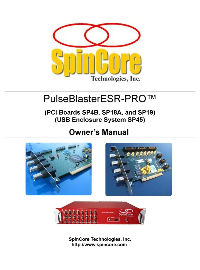
SpinCore Technologies PulseBlasterESR-PRO SP4B User manual
SpinCore Technologies
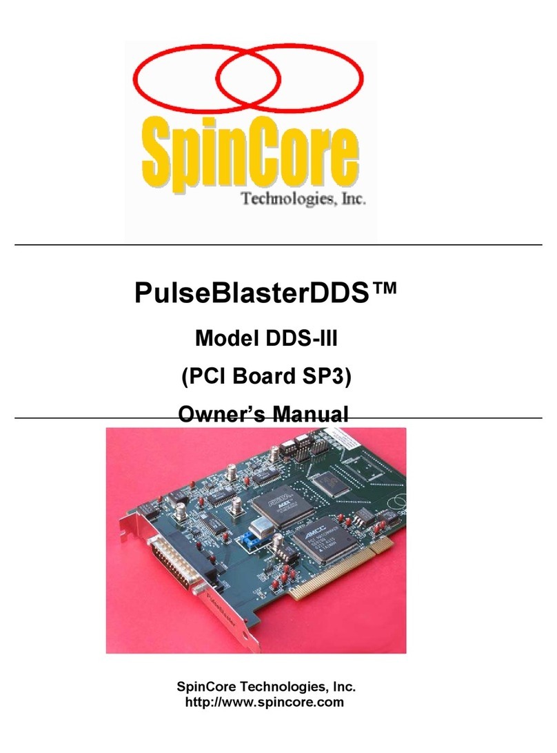
SpinCore Technologies PulseBlaster DDS-III User manual
SpinCore Technologies
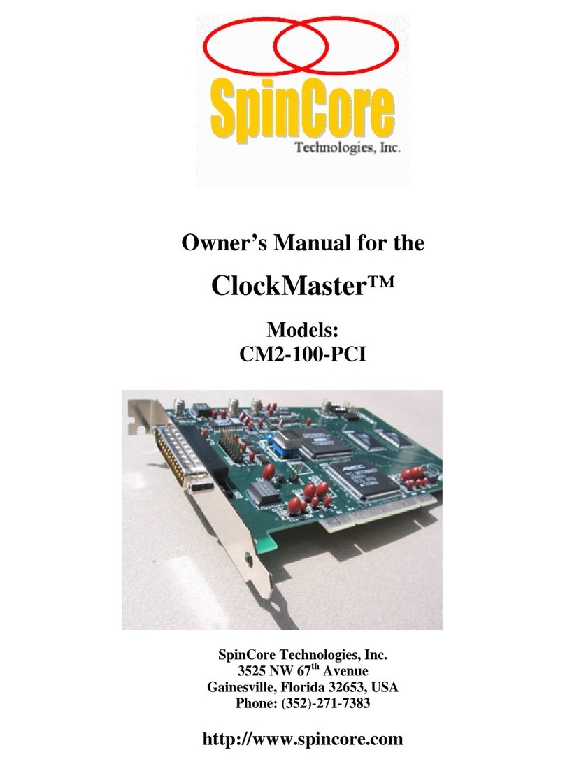
SpinCore Technologies ClockMaster CM2-100-PCI User manual
SpinCore Technologies
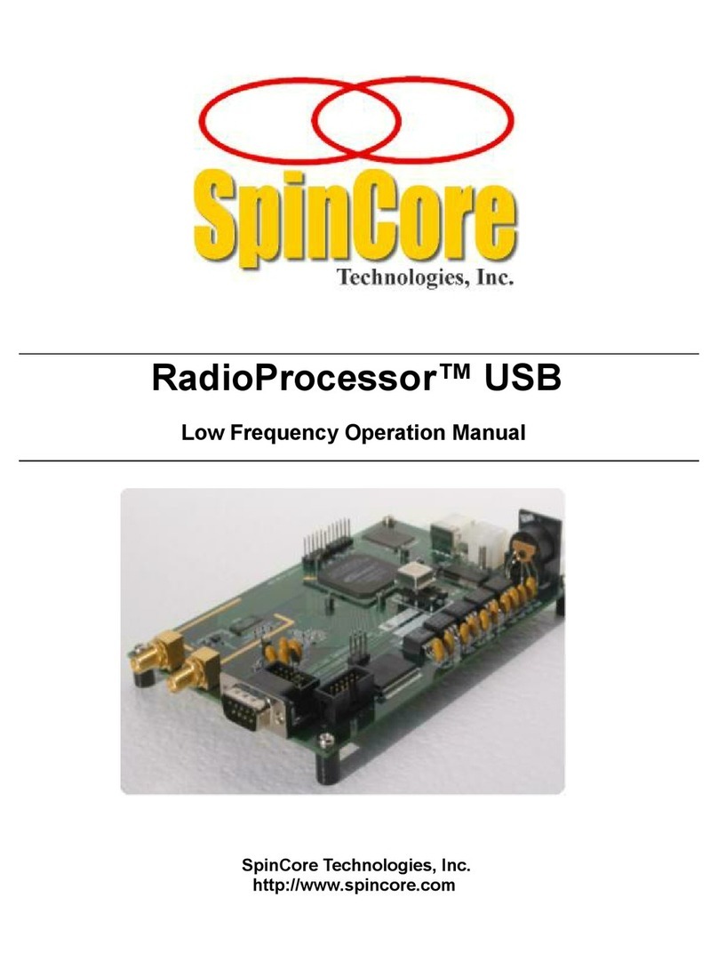
SpinCore Technologies RadioProcessor USB User manual
SpinCore Technologies
SpinCore Technologies PulseBlaster PB24-100-PCI User manual
SpinCore Technologies
SpinCore Technologies RadioProcessor-G User manual
