Spinlab Bird Dog Plus 5000 User manual

Spinlab Utility Instrumentation, Inc. March 1, 2009
6000 & 5000
Bird Dog Plus
FIELD USER GUIDE
Version 7.52F


i
INTRODUCTION
This Field User Guide is complementary to the 6000 & 5000 Bird Dog Plus Instruction
Manual, which gives you a detailed description of the equipment and its use. This guide is an
aid for field use while the manual is a reference for the lab or office use.
The purpose of this document is to provide a quick and easy guide for field use of the 6000 &
5000 Bird Dog Plus meter and meter circuit analyzers as well as accessories. With this guide
you will be able to very quickly learn the operation of the Bird Dog Plus.
6000 Bird Dog Plus Introduction to the Field User Guide
If you have the 6000 Bird Dog Plus, your first step will be to review theSETUP
PROCEDURE FOR THE 6000 BIRD DOG PLUS ONLY in Section F.1. After that, you
will need to review the Standard Test Procedures as illustrated below:
Meter Circuit Test—Section F.2.1—For the 6000 or 5000 Bird Dog Plus
Simultaneous 3 Phase Meter Verification Test—Section F.2.3—For the 6000 Bird Dog
Plus
5000 Bird Dog Plus Introduction to the Field User Guide
If you have the 5000 or 5000 MV Bird Dog Plus, your first step will be to review the
Standard Test Proceduresas illustrated below:
Meter Circuit Test—Section F.2.1—For the 6000 or 5000 Bird Dog Plus
Meter and Meter Circuit Test—Section F.2.5—For the 5000 MV Bird Dog Plus
Meter Test Only—Section F.2.7—For the 5000 MV Bird Dog Plus
The Screen Flows that follow the Standard Test Proceduresshould make it very easy to
verify the screen you are on and what screen to expect next. A more detailed description of
the information on each screen is contained in the 6000 & 5000 Bird Dog Plus Instruction
Manual.
Section F.3 contains detailed procedures for hooking up your probes & sensors when
performing the meter verification test for the following:
5000 MV Bird Dog Plus— Section F.3.1
6000 Bird Dog Plus— Section F.3.2
Meter Sensor Hookup Procedure— Section F.3.3
Happy testing.

ii
TABLE OF CONTENTS Page #
INTRODUCTION i
TABLE OF CONTENTS iii
SECTIONS
F.1 SETUP PROCEDURE FOR THE 6000 BIRD DOG PLUS 1
ONLY
F.1.1 6000 Bird Dog Plus Case 1
Note: Connecting the Large I Probes to the 6000 Bird Dog Plus 2
F.1.2 3 Phase Connector Box 3
Note: Previous Owners of the 1500 High Voltage Kit 5
F.2 STANDARD TEST PROCEDURES 7
F.2.1 STP for Single Element Meter Circuit Testing 7
F.2.2 Screen Flow for Single Element Meter Circuit Testing 9
F.2.3 STP for 6000 Bird Dog Plus Simultaneous 3 Phase Meter 13
Verification Testing After a Meter Circuit Test
F.2.4 Screen Flow for 6000 Bird Dog Plus Simultaneous 3 Phase 15
Meter Verification Testing After a Meter Circuit Test
F.2.5 STP for 6000 Bird Dog Plus Simultaneous 3 Phase Meter 19
Verification Testing on a Self-Contained Meter
F.2.6 Screen Flow for 6000 Bird Dog Plus Simultaneous 3 Phase 21
Meter Verification Testing on a Self-Contained Meter
F.2.7 STP for 5000 MV Single Element Meter & Meter Circuit 27
Testing
F.2.8 Screen Flow for 5000 MV Single Element Meter & Meter 29
Circuit Testing
F.2.9 STP for 5000 MV Single Element Meter Verification 35
Testing
F.2.10 Screen Flow for 5000 MV Single Element Meter Verification 37
Testing & a Form 2 Meter
F.2.11 STP for the 1500 High Voltage Probe Operation 43
F.2.12 STP for UploadingRecords to the PC 51
F.2.13 Screen Flow for Uploading Records to the PC 53
(Communication Troubleshooting Guide) 57

iii
F.2.14 STP for Producing a Meter & Meter Circuit Report using 61
SpinGraph
F.2.15 Screen Flow forProducing a Meter & Meter Circuit Report 63
using SpinGraph
F.2.16 Procedures for Using the MB1 Meter Base Adapters 75
F.2.16.1. Spinlab 600-MB1 (SP 1850) Plug-in Meter Base 75
Adapter--Form 3S & 4S Meters
F.2.16.2. Spinlab 600-MV-MB1 Plug-in Meter Base 77
Adapter with Test Switches--Form 3S & 4S Meters
F.3 PROBE & SENSOR HOOKUP PRODEDURE FORMETER 81
VERIFICATION TESTING ONLY
F.3.1 6000 or 5000 Bird Dog Plus Probe Hookup Procedure for 81
Single Phase MV
Note: Probes & Connections to Use for 6000 Bird Dog Plus 82
Owners
F.3.1.1 Form 3 Meters 83
F.3.1.2 Form 4 Meter 83
F.3.1.3 Form 5 Meters 84
F.3.1.3.1 Form 5 Network 84
F.3.1.3.2 Form 5 Meter: 4 Wire Wye 84
F.3.1.3.3 Form 5 Meter: 3 Wire Delta 85
F.3.1.3.4 Form 5 Meter: 4 Wire Delta 85
F.3.1.4 Form 6 Meter: 4 Wire Wye 86
F.3.1.5 Form 8 Meter: 4 Wire Delta 87
F.3.1.6 Form 9 Meters: 4 Wire Wye or 4 Wire Delta 88
F.3.1.7 Form 1 Meter: 2 Wire 89
F.3.1.8 Form 2 Meters: 2 & 3 Wire 89
Note: Ensure a .5 Amp Minimum on Each Conductor 90
of a Form 2 Circuit
F.3.1.9 Form 12 Meters 91
F.3.1.9.1 Form 12 Meter: Network 91
F.3.1.9.2 Form 12 Meter: 3 Wire Delta 91
F.3.2 Probe Hookup Procedure for Simultaneous 3 Phase Testing 93
(6000 Bird Dog Plus Only)
F.3.2.1 Form 3 Meters 94
F.3.2.2 Form 4 Meter 95
F.3.2.3 Form 5 Meters 95
F.3.2.3.1 Form 5 Network 95
F.3.2.3.2 Form 5 Meter: 4 Wire Wye 96
F.3.2.3.3 Form 5 Meter: 3 Wire Delta 97
F.3.2.3.4 Form 5 Meter: 4 Wire Delta 97
F.3.2.4 Form 6 Meter: 4 Wire Wye 98
F.3.2.5 Form 8 & 9 Meter: 4 Wire Delta 99
F.3.2.6 Form 9 Meters: 4 Wire Wye 99
F.3.2.7 Form 1 Meter: 2 Wire 100

iv
F.3.2.8 Form 2 Meters: 2 & 3 Wire 101
Note: Ensure a .5 Amp Minimum on Each Conductor 101
of a Form 2 Circuit
F.3.2.9 Form 12 Meters 102
F.3.2.9.1 Form 12 Meter: Network 102
F.3.2.9.2 Form 12 Meter: 3 Wire Delta 103
F.3.2.10 Form 14 Meters: 4 Wire Wye 104
F.3.2.11 Form 15 & 17 Meter: 4 Wire Delta 104
F.3.2.12 Form 16 Meter: 4 Wire Wye 105
F.3.3 Meter Sensor Hookup Procedure 107
F.3.3.1 Laser Sensor for Mechanical Meters 107
Note #1—Don’t Look into Laser 108
Note #2--Laser Sensitivity Adjustment 108
F.3.3.2 Laser Sensor for Electronic Meters 108
F.3.3.3 Infrared Sensor 109
Note #1—Unnecessary to Disconnect Laser Sensor When Using 110
Infrared Sensor
Note #2—OPTOCOM Port with a Separate LED for 110
Infrared Pulse
F.3.3.4 Optional Sensors and Pickups 111
F.3.3.5 Detecting Rotations or Pulses on the Bird Dog Plus 112
Note—How to Get Pulses Out of Electronic Meters 113

1
SECTION F.1
SETUP PROCEDURE
FOR 6000 BIRD DOG PLUS ONLY
F.1.1 6000 Bird Dog Plus Case
The 6000 Carrying Case has been ergonomically designed to work with the 6000 Bird Dog
Plus. It is an integral part of your new unit. The dimensions are 15.5” x 9.5” x 17.5”. When
you first open the top flap on the carrying case, you will see 3 distinct compartments with
labels. These labels will help you to quickly identify the probe sets or sensors you need.
Everything you will need for low voltage testing of meters and meter circuits is contained in
that carrying case. In addition all the probes are pre-connected to the 6000 Bird Dog Plus, so
connecting and disconnecting the probes and sensors is a thing of the past. Just pull the
connections that you need out of the case, connect them to the site, and put them back in their
appropriate compartment after you are through.
The curved indention on the front panel of the carrying case is there to conveniently
hold your hand in place while you operate the Bird Dog Plus.
The 1st compartment is where the 6000 Bird Dog Plus, 3 Phase Connector Box and the
voltage cable are located.
The 2nd compartment is where the flexible coil probe, duckbill connectors, and the
small current probes are located.
The 3rd or rear compartment is where the following reside:
oMeter sensors
oLarge I Probes and/or the High Voltage Probe with Fiber Optic
Cable—Both the Large I Probes and the High Voltage Probe with fiber
optic cable are contained in the same case, when the 1500 High Voltage Kit
is ordered with the 6000 as shown below. When the 1500 High Voltage
Kits is not ordered with the 6000 the Large I Probes are contained in a
separate carrying pouch shown below. Attach both as needed to the 6000
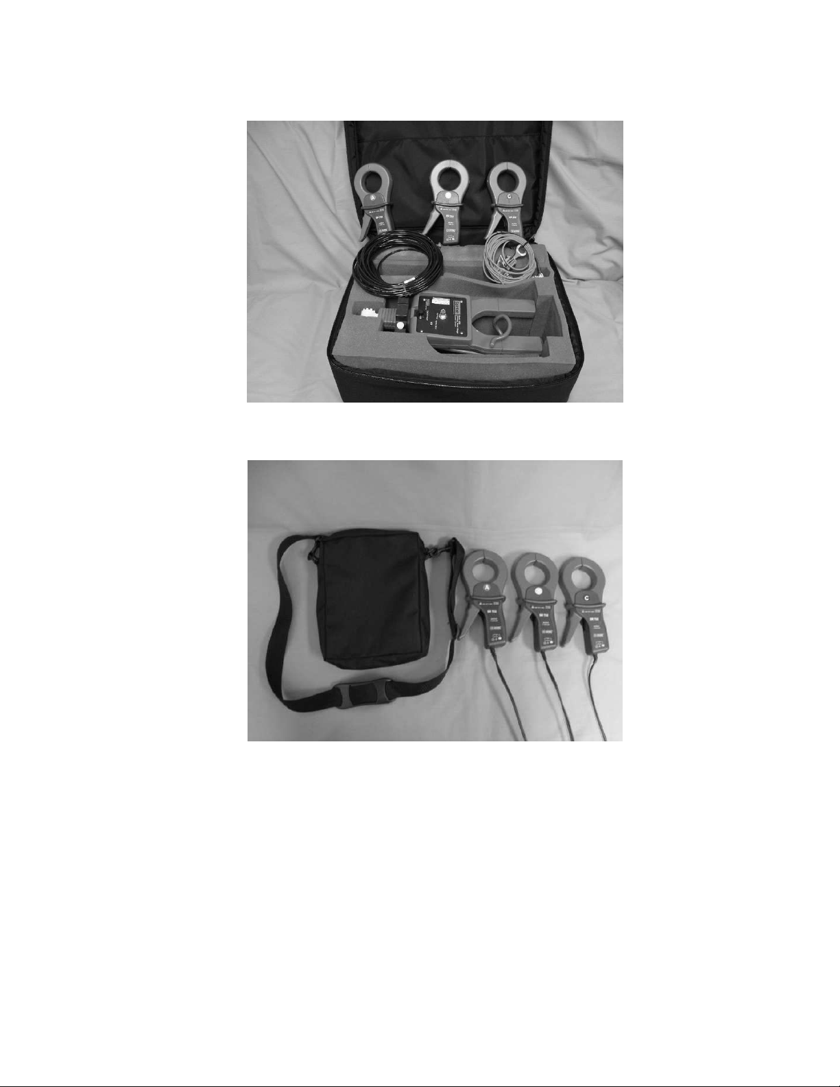
2
Bird Dog Plus. If you want either the High Voltage Probe with fiber optic
cable or the Large I Probes can be carried in the 3rd compartment of the
6000 Bird Dog Plus case if you prefer.
High Voltage Case--Location of the Large I Probes when the 1500 High Voltage Kit is
ordered.
Carrying Pouch--Location of the Large I Probes when the 1500 High Voltage Kit is NOT
ordered.
Note: Connecting the Large I Probes to the 6000 Bird Dog Plus—When you
connect the Large I Probes to the 6000 Bird Dog Plus, all 3 probes have been joined
together to 1 connector. Take this connector and attach it to the connector’s mate in
the 3rd compartment of the 6000 carrying case.
oPush button for manual meter verification testing
Behind the 3rd compartment is a carrying pouch where the manuals or any other
paperwork can be maintained.
The zipper on the back is used for assembly and disassembly of the parts of the 6000
Bird Dog Plus, normally performed at the factory.
3
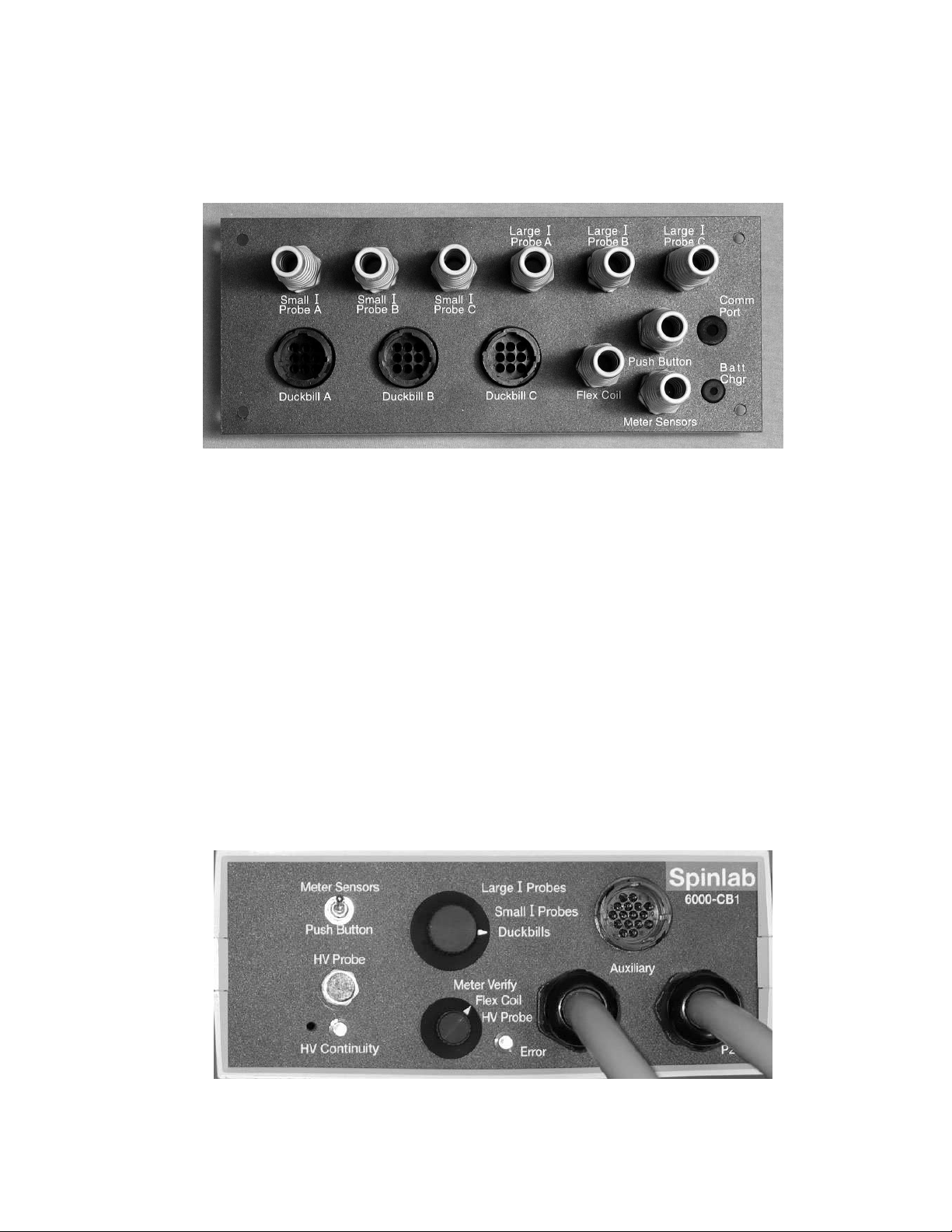
F.1.2 3 Phase Connector Box
The purpose of the 3 Phase Connector Box is to provide a means for nearly all accessories to
be pre-connected to the 6000 Bird Dog Plus. The cable connections are all different so it is
impossible to connect a probe or sensor to the wrong lead. The probes and sensors are
connected to the bottom of the 3 Phase Connector Box through gaps in the bottom of the case.
The following is a list of everything connected to and through the rear of the 3 Phase
Connector Box:
Small I Probes--3 connections for the Small I Probes (A, B, & C)
Large I Probes--3 connections for the Large I Probes (A, B, & C)
Duckbill—3 connections for the duckbill connectors (A, B, & C)
Flex Coil--Connector for the Flexible Coil Probe
Meter Sensors--Connector for the laser and infrared sensors for meter verification testing
Push Button--Connector for the push button for meter verification testing
Plastic supports are used to keep the 3 Phase Connector Box at the same level as the 6000
Bird Dog Plus. Inside the 3 Phase Connector Box are connections for up to 2 extra batteries
(this is for future use and you should not need them for normal operation of the 6000 Bird Dog
Plus), and if you purchased a 1500 High Voltage Kit from Spinlab, the Retriever Interface
Card is inside the box as well. The only thing that you need to be concerned about is the front
panel of the 3 Phase Connector Box:
The following is a detailed description of everything on the front panel and how it works:

4
Meter Trigger Switch--Switch to tell the Bird Dog Plus if you are using the Meter
Sensors or the remote Push Button to perform the meter verification test. If you are not
performing meter verification testing, it does not matter the position of the switch. More
on the use of the Meter Sensors in Section F.3.3 of this manual.
HV Probe--Connector for the High Voltage fiber optic cable—Retriever Interface circuit
board is inside the 3 Phase Connector Box.
HV Continuity—Red LED to show that the High Voltage Probe is communicating with
the 6000 Bird Dog Plus.
Large Knob--Switch to select which probes or other input device you are using:
oLarge I Probes—Large current probes, 2 inch inside diameter, 10A to 1000A. If you
need longer extensions for your current probes to get to the weatherhead, for example,
contact Spinlab.
oSmall I Probes—Small current probes, .75 inch inside diameter, .5A to 100A
oDuckbills—Used for a direct connection to a test switch—copper side up, .1 to 20A
Small Knob--Switch to determine the operational setting of the Bird Dog Plus:
oMeter Verify--Use when you are testing an entire meter with 1 test or testing individual
phases one at a time
oFlex Coil—Use when the low voltage Flexible Coil probe is in use for ratio/burden
testing, 10A to 3000A
oHV Probe--Use when the High Voltage probe is in use for ratio/burden testing. 2A to
2000A, 230kV maximum
Error—Red LED lets you know if the switch selections you have made are valid. If you
chose an invalid selection, then you must turn off the unit, change your switch settings and
turn the 6000 Bird Dog Plus back on.
The following table will explain the different ways that the 6000 Bird Dog Plus can be
configured depending upon the meter type and the test(s) you want to perform. When the
Bird Dog Plus is turned on, the switch position is locked in. To change the switch
selection, you must first turn the Bird Dog Plus off, change the switch setting(s), and then
turn the unit back on. Only then will the unit recognize the new switch positions. The
following lists all possible knob settings and the resulting test that can be performed while
using these settings:
Small Knob Large Knob Resulting Test
oMeter Verify Large I Probes Testing a form 1, 2, 12, 14, 15, 16, or 17
meter
oMeter Verify Small I Probes Performing a meter test on any meter
oMeter Verify Duckbills Testing a form 3, 4, 5, 6, 8, or 9 meter
oFlex Coil Large I Probes Invalid—Red Error LED Comes On!
oFlex Coil Small I Probes Performing a meter and or meter circuit test
(GS and/or GV) on a CT rated meter (no
burden results & low voltage only)
oFlex Coil Duckbills Testing a form 3, 4, 5, 6, 8, or 9 meter
circuit (low voltage CTs only)
oHV Probe Large I Probes Invalid—Red Error LED Comes On!
oHV Probe Small I Probes Performing a meter and or meter circuit test
(GS and/or GV) on a CT rated meter (no
burden results)

5
oHV Probe Duckbills Testing a form 3, 4, 5, 6, 8, or 9 meter
circuit (high or low voltage CTs)
When you turn on the 6000 Bird Dog Plus, after the logo screen appears, you will see a
screen that says, “Following Switch Positions Detected.” Make sure that these switch
selections correspond to the test you plan to perform. If not, turn the unit off, change the
switch positions, and turn the 6000 Bird Dog Plus back on.
Auxiliary—Future Use
P2--Connector going to the P2 port of the Bird Dog Plus
P3--Connector going to the P3 port of the Bird Dog Plus
Note—Previous Owners of the 1500 High Voltage Kit:If you are upgrading your 5000
Bird Dog Plus to a 6000 Bird Dog Plus and you previously owned a 1500 High Voltage
Kit, the circuit board that was in your Retriever Interface Box has now been incorporated
into the 3 Phase Connector Box, making your connection to the 6000 Bird Dog Plus much
easier. Simply connect the fiber optic cable to the 3 Phase Connector Box and connect the
other end of the fiber optic cable to the probe head.
Now you are ready to begin connecting your probes to the site and start testing with your6000
Bird Dog Plus.

6

7
SECTION F.2.1
STANDARD TEST PROCEDURE FOR SINGLE ELEMENT
METER CIRCUIT TESTING ONLY
(Save ONLY the GLOB SAVE Screen—Forms 3, 4, 5, 6, 8, 9 Meter
Circuits)
1. Hookup Probes to Phase A (or B or C as appropriate)
1.1 Primary Current: Flex Coil--Arrow towards load, High Voltage--Large Dot
Toward Line
1.2 Secondary Current: Duckbill / Copper side up (If 6000 Bird Dog Plus owner,
use only phase A duckbill with the large knob on the 3 Phase Connector Box
set to Duckbills and the small knob set to either Flexible Coil or High
Voltage.)
1.3 Secondary Voltage: Alligator Clips /Red to phase A (or B or C), Black to phase
C (Connect to phase C on the lug above the switch & leave it there for the entire
test.), and white to neutral/low side. (If 6000 Bird Dog Plus owner, leave Yellow
(or green for older units) alligator clip unconnected.)
1.4 Confirm Proper Voltage Wiring from the Test Switch to the Meter
(Skip this section if using Meter Base Adapters.)
1.4.1 Short phase B & C CTs and confirm the meter is reporting phase A
1.4.2 Short phase A & C CTs and confirm the meter is reporting phase B
1.4.3 Short phase A & B CTs and confirm the meter is reporting phase C
1.4.4 Close all CT shorting switches
2. Turn the Bird Dog Plus On
3. Enter Meter/Circuit/Rotation
3.1 If listed data is the same as your circuit: press YES and go to 4.1
3.2 If listed data is different than your circuit: press NO, select correct data and go to 4.1
3.3 If your circuit is not known or irrelevant: press UNDEFINED and go to 4.1
4. Enter LOCATION CODE
4.1 FromLOCATION CODE screen press CHANGE button. Arrow points to
first digit
4.2 Press theCLEAR button
4.3 Cycle the far left button 0-9, A-Z+ until the desired digit appears
4.4 Press theMORE button
4.5 Press NXT DIGIT. Arrow advances to next digit. Takes you back to previous
screen
4.6 Repeat 4.3 through 4.6 until new location code entered
4.7 When the new location code is entered, press theMORE button twice
4.8 Press theSAVE to store new LOCATION CODE and go to the MAIN MENU
5. Review the WIRE VERIFY GRAPH & Run the RATIO/BURDEN TEST
5.1 Select WV GRAPH from theMAIN MENU—the bottom right button
5.2 Select PHASE A (or B or C)
5.3 Review the readings as follows:

8
Primary Current—OK? (>10% of rated ratio, steady)
Secondary Voltage—OK? (Correct value, steady)
Secondary Current—OK? (>0.5 Amps, steady, balanced)
True PF—OK? (>0.7, steady)
Phase Angles—OK? (steady, adjust for inherent phase shift)
THD Voltage--OK (<5.0%, steady)
THD Current--OK (<20.0%, steady)
5.4 Select EXIT
5.5 Select CT RATIO/BURDEN TEST
5.6 Select PHASE A (or B or C)
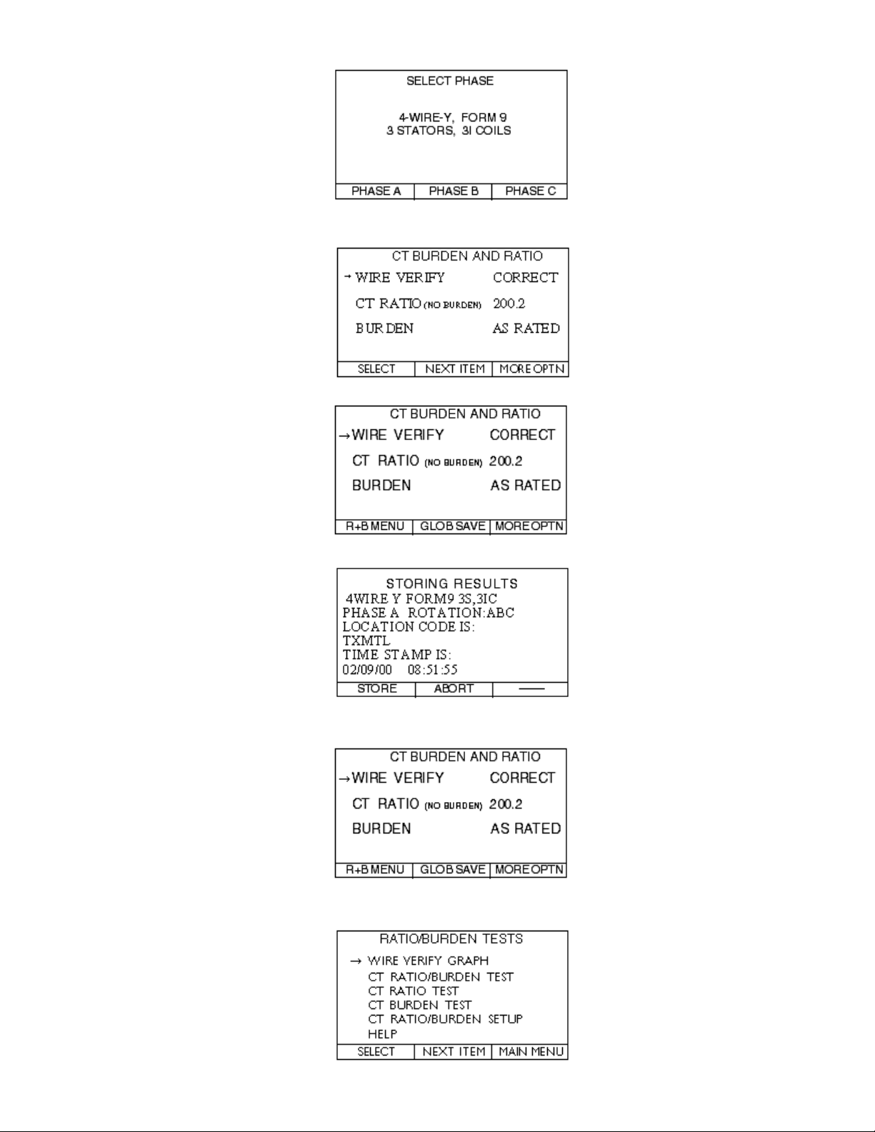
6. Review Results of CT Ratio/Burden Test
WIRE VERIFY--OK? (Correct/See Graph)
RATIO (NO BURDEN)—OK? (within 2% of Rated Ratio)
BURDEN--OK? (As Rated/Error ohms)
6.1 If you need to troubleshoot, go to appropriate choice and press
SELECT to proceed
6.2 If all OK, press MORE OPTN
6.3 Press GLOB SAVE (Save ONLY the GLOB SAVE Screen)
6.4 Press STORE
6.5 You have now finished Phase A (or B or C); if C, go to Step 8
7. Move Probes to the Next Phase
7.1 Currently inCT BURDEN AND RATIO screen
7.2 Press R&B MENU
7.3 Go back to Step 5.2 and repeat through Step 7.2
8. 6000 Bird Dog Plus Users Only! If you are also performing a Simultaneous 3 Phase Meter
Verify Test, go to Section F.2.3 of this manual and follow the procedure.
9. Wrap Up Procedure--After testing, turn off Bird Dog Plus, leaving cables connected.
Coil secondary voltage and current cables together into case, and then coil the flexible
coil into the case and close flap. Move to the next site.
9
SECTION F.2.2
SCREEN FLOW FOR SINGLE ELEMENT
METER CIRCUIT TESTING
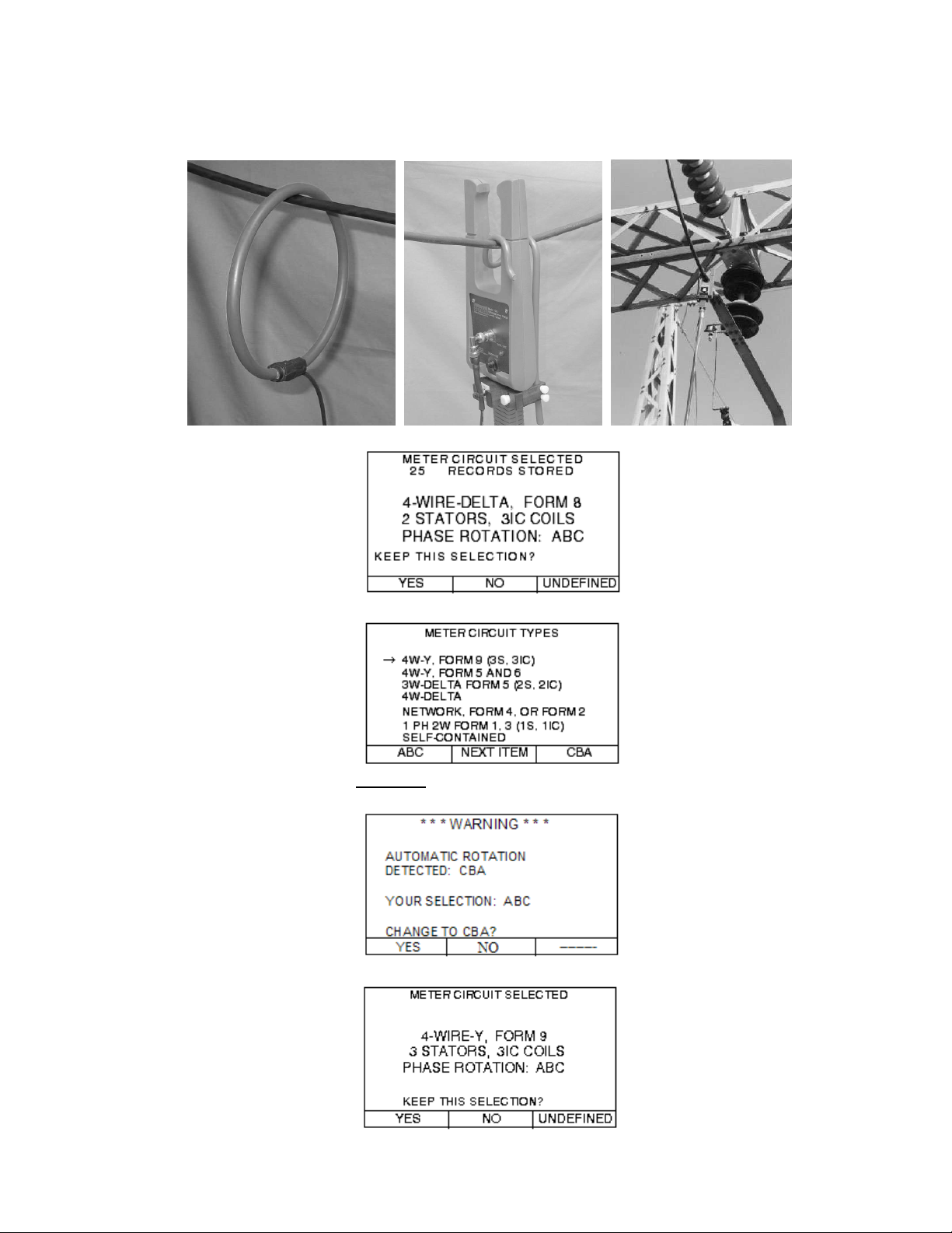
Step 1.1—Hook up the Flexible Coil Probe or the High Voltage Probe like this:
Step 3.1—Select NO if this is not the correct meter type & rotation.
Step 3.2—Select the correct meter type & rotation.
Step 3.2— If you are incorrect as to the rotation, you will see the following message.
Press theYES button:
Step 3.2—Confirm the meter type & rotation selected.
10
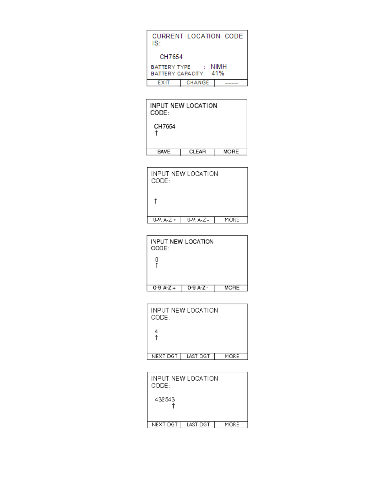
Step 4.1—Press the CHANGE button.
Step 4.2—Press the CLEAR button.
Step 4.3—Press the 0-9, A-Z+ button to start the first digit.
Step 4.4—Press the MORE button.
Step 4.5—Press the NEXT DGT button.
Step 4.6—Repeat the steps above until the entire LOCATION CODE is entered.

11
Step 4.8—Press the SAVE button and you will be taken to the MAIN MENU.
Step 5.1—SELECT WV GRAPH—the bottom right button.
Step 5.2—Select the PHASE you are testing.
Steps 5.3—Review the wire verify graph for appropriate readings & press EXIT.
Proper Wiring Bad Hook Up or Cross Wired Circuit
Leads Reversed or Duckbill Backwards
Step 5.5—Select CT RATIO/BURDEN TEST.
12
Step 5.6—Select the PHASE you are testing.
Steps 6.0 - 6.2—Review the CT BURDEN AND RATIO screen for appropriate
readings. Press the MORE OPTN button.
Step 6.3—Press the GLOB SAVE button and the following screen will appear.
Step 6.4—Press the STORE button.
Steps 6.5 & 7.1—You are automatically taken back to the CT BURDEN AND RATIO
screen.
Press the R+B MENU button.
Step 7.2—Select the WIRE VERIFY GRAPH go back to Step 5.2 & test the next phase.

13
SECTION F.2.3
STANDARD TEST PROCEDURE FOR 6000 BIRD DOG PLUS
SIMULTANEOUS 3 PHASE METER VERIFICATION
TESTING AFTER A METER CIRCUIT TEST
1. Hookup Probes to Phase A (or B or C as appropriate) & Sensors to the Meter
1.1 Secondary Current: Depending upon the type of circuit you are testing, there will be
different hookup procedures. See Section F.3.2 for more detailed hookup procedures:
1.1.1 Forms 3, 5, 6, 8, & 9 Circuits with a Test Switch: Duckbills / Copper side up or
clamp-on CTs (Small I Probes)
1.1.2 Forms 4 Circuits with a Test Switch: Duckbills / Copper side up for phase 1
and silver side up for phase 2, or clamp-on CTs (Small I Probes) with reverse
direction for phase 2.
1.2 Secondary Voltage: Alligator Clips /Red to phase A, yellow (or green for older units)
to phase B, black to phase C, & white to neutral/low side.
1.3 Automatic Sensors: Attach the automatic sensors to the meter.
1.4 3 Phase Connector Box: Set the 1) Small Knob to the Meter Verify position, 2) the
Large Knob to the proper probes (Large I Probes or Small I Probes or Duckbill
connectors) you are using, and 3) the Meter Trigger switch set to Sensors.
2. Transition From Meter Circuit Testing to Meter Testing
2.1 From theCT RATIO AND BURDEN screen, press the MORE OPTN button.
2.2 Press PP GRAPH.
2.3 With the 6000 on, change the setting on the small knob to Meter Verify. Change the
setting on the large knob if necessary. PressCONTINUE.
3. Review the POLYPHASE GRAPH for Input Signals
3.1 Review the AMPLITUDE readings
3.2 Press NEXT VIEW and scroll through PHASE (DEG) angles, HARMONIC
DISTORTION readings, and then finally the SYSTEM POWER SUMMARY
screen for anomalous readings as shown below:
Secondary Currents—OK? (>0.5 Amps, steady,
balanced)
Phase Angles—OK? (steady, adjust for inherent
phase shift)
THD Readings—THDV < 5% & THDI < 20%
System Power Readings
True PF—OK? (>0.7, steady)
Secondary Voltages—OK? (Correct value, steady)
3.3 Press MV MENU when your review is complete
4. Perform the Meter Verification Test
4.1 From theMETER VERIFY TEST menu select METER VERIFY ONLY
4.2 Enter the appropriate Kh and press SELECT
4.3 INPUT NUMBER OF PULSES PER REVOLTION for which the meter is set
4.4 Now setup your sensors on the SENSOR SETUP screen
4.5 Once the sensors are detecting a proper pulse or rotation, press the AUTOMATIC button
4.6 The Bird Dog Plus will now detect the length of time for the test and will bring you to the
TIMING RESULTS screen
14
4.7 Press the START button (or wait 5 seconds). Once the sensor sees a pulse or a disk
rotation, the test will begin. The test will automatically stop once the final revolution or
pulse is detected.
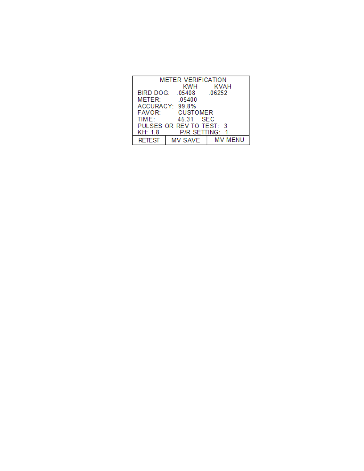
5. Review Results of Meter Verify Test & Save Results
5.1 Insure that the accuracy is within your tolerance specification.
Test Time > 30 Seconds?
Accuracy OK?
5.2 Press the MV SAVE button
5.3 Press STORE if all is OK. Press ABORT if a correction is needed
5.4 You have now finished testing the accuracy of the entire meter (all 3 phases) and
storing the data in memory.
6. Wrap Up Procedure--After testing, turn off Bird Dog Plus, leaving cables connected. Coil
secondary voltage and current probes into their appropriate compartments. Then coil the
sensors and put them in their compartment. Close the case lid. You are done.
This manual suits for next models
1
Table of contents
Popular Pet Care Product manuals by other brands


Garmin
Garmin TT 10 user manual

Zolia
Zolia RUMBA quick start guide

Tunze
Tunze Turbelle stream 6065 Instructions for use

KT contribution
KT contribution Feed'em user guide

Wildlife Materials International
Wildlife Materials International 3190 quick start guide

Petrainer
Petrainer CVJC-G340-2GEN quick start guide


