Spinner II BN 754081 User manual

Coaxial Two Way Switch (DPDT)
BN 754081
RF Interface 7-16 Female
BN 754082
RF Interface 4.3-10 Female

Data subject to change without notice │M36326 │Issue C
www.spinner-group.com
2 / 18
Content
1.Basic Safety Instructions for SPINNER Broadcast Products...................................................................3
2.Intended use.............................................................................................................................................6
3.Improper use ............................................................................................................................................6
4.Function....................................................................................................................................................6
4.1Impulse solenoid drive .............................................................................................................................6
4.2Hypocycloid gear......................................................................................................................................6
4.3Bistable switching property (latching).......................................................................................................7
4.4Manual override........................................................................................................................................7
4.5Visual position indicator ...........................................................................................................................7
4.6Interlock / signal contacts.........................................................................................................................7
4.7Earthing terminal ......................................................................................................................................7
5.Data sheet ................................................................................................................................................8
6.Outline (all dimensions in millimeters)....................................................................................................11
7.Circuit diagram (B24140-CD, Issue D)...................................................................................................12
8.Storage...................................................................................................................................................13
9.Transportation ........................................................................................................................................13
10.Installation ..............................................................................................................................................13
10.1Mechanical installation ...........................................................................................................................14
10.2RF installation.........................................................................................................................................14
10.3Electrical installation...............................................................................................................................14
11.Commissioning.......................................................................................................................................15
12.Operation................................................................................................................................................15
13.Cleaning .................................................................................................................................................15
14.Maintenance...........................................................................................................................................16
15.Repairs ...................................................................................................................................................16
16.Warranty.................................................................................................................................................16
17.Demounting ............................................................................................................................................16
18.Disposal..................................................................................................................................................17
19.Additional endangering (regardless to life cycle) ...................................................................................17
20.Environmental friendly usage period......................................................................................................18
21.Spare parts.............................................................................................................................................18
22.Contacts .................................................................................................................................................18

Data subject to change without notice │M36326 │Issue C
www.spinner-group.com
3 / 18
1. Basic Safety Instructions for SPINNER Broadcast Products
The following instructions and safety instructions are to be carefully read and followed!
The Spinner group makes every effort to keep the safety standard of our products up to date to be able to offer our
customers the highest possible degree of safety. Our products are designed and tested in accordance with the relevant
safety standards. Compliance with these standards is continuously monitored by our quality assurance system. The
product described here has been designed and tested in accordance with the respective EU guidelines and has left the
manufacturer’s plant in a condition fully complying with safety standards. To maintain this condition and to ensure safe
operation, observe all instructions and warnings provided. If you have any questions regarding these safety instructions,
the Spinner group will be happy to answer them.
The operator is responsible for using the product in an appropriate manner. This product must not be used in any way that
may cause personal injury or property damage. The operator is responsible if the product is used for an intention other
than its designated purpose or in disregard of the manufacturer's instructions. The manufacturer shall assume no
responsibility for such use of the product.
The product is used for its designated purpose if it is used according to the specifications listed in the product’s
documentation within its performance limits (see data sheet, performance specifications, circuit diagram, the following
safety instructions).
Putting the product into operation requires special technical skills and must be executed by qualified personnel with
reference to “Start-up information” in the product documentation. Keep the basic safety instructions and the product
documentation in a safe place and pass them on to the subsequent users.
Symbols and safety markings
General hazard Warning!
Risk of
electric shock
Warning!
Hot surface
PE terminal Earthing
terminal
Warning!
High weight
Warning!
Non-ionised
electromagnetic
radiation
Pacemaker
hazard area
Use foot guard Use eye
protection
Use safety
gloves
Observe product
documentation
Observing the safety instructions will help prevent personal injury or damage of any kind caused by dangerous situations.
Therefore, carefully read through and adhere to the following safety instructions before putting the product into operation. It is also
absolutely essential to observe the additional safety instructions on personal safety that appear in relevant parts of the
product documentation.
Tags and their meaning
DANGER Indicates a hazardous situation conveying great risk which, if not avoided, will result in death or serious
injury.
WARNING Indicates a hazardous situation conveying moderate risk which, if not avoided, could result in death or
serious injury.
CAUTION Indicates a hazardous situation conveying minor risk which, if not avoided, may result in minor or moderate
injury.
ATTENTION Indicates the possibility of faulty operation that can damage the product.
These tags are in accordance with the standard definition for civil applications in the European Economic Area. Definitions
that deviate from the standard definition may also exist in other economic areas or military applications. It is therefore
essential to make sure that the tags described here are always used only in connection with the related product
documentation and the related product. The use of tags in connection with unrelated products or documentation can result
in misinterpretation and thus contribute to personal injury or material damage.

Data subject to change without notice │M36326 │Issue C
www.spinner-group.com
4 / 18
1. These products must be operated only under the operating conditions specified in the product documentation. All
instructions for start-up, operation and servicing listed in the product documentation have to be observed.
2. Applicable local or national safety regulations and rules for the prevention of accidents must be observed in all
work performed. Only authorized and specially trained personnel shall work with these products.
3. Operating the products requires special training and intense concentration. Make sure that persons who use the
products are physically, mentally and emotionally fit enough to do so; otherwise, injuries or material damage may
occur. It is the responsibility of the employer/operator to select suitable personnel for operating the products.
4. The product must be installed and operated in operating sites with limited access only. Access for authorized
qualified personnel must be regulated by the operator.
5. Unless otherwise specified, these products are not protected against penetration of liquids, gases, steam, etc. If
this is not taken into account, there exists the danger of electric shock for the user or damage to the product, which
can also lead to personal injury.
6. Never use the product under conditions in which condensation has formed or can form in or on the product, unless
otherwise specified.
7. These products are not explosion protected. They must not be operated in explosion-prone areas.
8. Do not place the product on heat-generating devices such as radiators or fan heaters. The ambient temperature
must not exceed the maximum temperature specified in the product documentation. Product overheating can
cause electric shock, fire and/or serious personal injury or death.
9. Do not place the product on surfaces, vehicles, cabinets or tables that for reasons of weight or stability are
unsuitable for this purpose. Always follow the manufacturer's installation instructions when installing the product
and fastening it to objects or structures (e.g. walls and shelves). An installation that is not carried out as described
in the product documentation could result in personal injury or death.
10. The product may be very heavy. Therefore, the product must be handled with care. In some cases, the user may
require suitable lifting gear to avoid back or other physical injuries.
11. The user is responsible for safe transport, parking and storage of the product. When using auxiliary objects (e.g.
lifting gear, trolleys, shelves), the user has the duty to review their suitability prior to use. Transport and storage of
the product are permitted only in the manufacturer's original packaging.
12. Handles on the product are handling aids and intended solely for people. Therefore, it is not permitted to use the
handles for mounting on or at means of transportation, e.g. cranes, carts etc. Lifting lugs serve for transportation
or lifting with crane.
13. Mains driven products must be operated only from a power distribution system. The operator is responsible for
using an appropriate and sufficiently dimensioned AC power line. The AC power line must be externally fused
according to the product documentation.
14. Operation of products of safety class I is only permitted with sufficient "Protective Earth" connection. Connection
to "Protective Earth" must be done in the way provided and described in the product documentation. The operator
is responsible for inspecting PE continuity by a qualified professional.
15. All connectors on cables from and to the product must be connected firmly. The connectors shall not be dusty or
dirty. Otherwise, danger of fire and/or injuries can occur. Intentionally breaking the protective earth connection
either in the AC power line or in the product itself is not permitted. Doing so can result in the danger of an electric
shock from the product. If extension cables are used, they must be sufficiently dimensioned and checked on a
regular basis to ensure that they are safe to use.
16. Do not overload any sockets, extension cords or connector strips; doing so can cause fire or electric shocks.
17. Operation of the product with a damaged cable is not permitted. All cables must be checked on a regular basis to
ensure that they are in proper operating condition. By taking appropriate safety measures and carefully laying the
power cable, ensure that the cable cannot be damaged and that no one can be hurt by e.g. tripping over the cable
or suffering an electric shock.
18. If the product is equipped with an earthing terminal connection (equipotential connection), the earthing terminal
must be connected sufficiently dimensioned to earth.
19. If a product is to be permanently installed, the connection between the PE terminal on site and the product's PE
conductor must be made first before any other connection is made. The product may be installed and connected
only by a licensed electrician.
20. For permanently installed equipment without built-in fuses, circuit breakers or similar protective devices, the supply
circuit must be fused in such a way that anyone who has access to the product, as well as the product itself, is
adequately protected from injury or damage.
21. Use suitable overvoltage protection to ensure that no overvoltage (such as that caused by a bolt of lightning) can
reach the product. Otherwise, the person operating the product will be exposed to the danger of an electric shock.
22. Any object that is not designed to be placed in the openings of the housing must not be used for this purpose.
Doing so can cause short circuits inside the product and/or electric shocks, fire or injuries.
23. Dangerous voltage must not reach the product over the outer conductor / waveguide.

Data subject to change without notice │M36326 │Issue C
www.spinner-group.com
5 / 18
24. All externally connected circuits for control, alarm and signalling must be supplied by SELV power sources (SELV
according to DIN EN 60950-1). The current in these circuits must be limited to the values specified in the product
documentation by means on an external fuse.
25. Before applying RF power to the product, it must be ensured that all connecting elements are professionally
connected and all unused ports are terminated. RF connections must have sufficient mechanical strength. If the
product features an interlock system, it must be connected and tested for function in advance.
26. Unless expressly permitted, never remove the cover or any part of the housing while the product is in operation.
Doing so will expose circuits and components and can lead to injuries, fire or damage to the product.
27. Repairs must be carried out by the manufacturer or technical personnel authorized by the manufacturer only.
28. As with all industrially manufactured goods, the use of substances that induce an allergic reaction (allergens) such
as nickel cannot be generally excluded. If you develop an allergic reaction (such as a skin rash, frequent sneezing,
red eyes or respiratory difficulties) when using a SPINNER product, consult a physician immediately to determine
the cause and to prevent health problems or stress.
29. Broadcasting systems or improper use of this product may produce an elevated level of electromagnetic radiation.
Considering that unborn babies require increased protection, pregnant women must be protected by appropriate
measures. Persons with pacemakers may also be exposed to risks from electromagnetic radiation. The
employer/operator must evaluate workplaces where there is a special risk of exposure to radiation and, if
necessary, take measures to avert the potential danger.
30. In the event of a fire, the product may release hazardous substances (gases, fluids, etc.) that can cause health
problems. Suitable measures must be taken, e.g. wearing of protective masks and protective clothing.
31. Products in operation may be hot. Touching them might cause burns.
32. If the product is pressurized, applicable local or national safety regulations for pressure equipment must be
observed.
33. Blocking of constructive openings on the product (ventilation slots, fine leaks etc.) must be prevented to ensure
safe operation.
34. Before cleaning, disconnect the product and all transmitters connected to the product from mains. Use a soft, but
not damp lint-free duster for cleaning. Do not use any chemical cleaning agents.
35. If handling the product releases hazardous substances or fuels that must be disposed of in a special way, e.g.
coolants that must be replenished regularly, the safety instructions of the manufacturer of the hazardous
substances and the applicable regional waste disposal regulations must be observed. Also observe the relevant
safety instructions in the product documentation. The improper disposal of hazardous substances can cause health
problems and lead to environmental damage.
36. The operator is responsible for disposing of the product according to national waste disposal regulations. Improper
disassembly or disposal may be hazardous.
37. SPINNER RF switches are not equipped with separating equipment for safe disconnection from mains. The user
must provide external separation equipment. The mains connector must be de-energized during plugging.
38. Do not actuate RF position Iand RF position II of RF switches simultaneously to avoid RF switch damage.
39. Do not touch or block the emergency manual override during electrical switch over to avoid injuries and switch
damage.
40. Disconnect RF switches from mains before using the emergency manual override of the drive unit to avoid injuries
and switch damage. The emergency manual override serves solely for switching the RF switch manually in a dead
state.
41. Switch over RF switches only without applying RF power to avoid injuries and damage. Hot switching with RF on
is not permitted. Ensure all switches are in the respective end position before applying RF power.
42. Switch off RF power before disconnecting RF connectors to avoid burns, eye injuries and electric shock. Utilize
appropriate devices and methods to prevent accidental energizing.

Data subject to change without notice │M36326 │Issue C
www.spinner-group.com
6 / 18
2. Intended use
The intended use of the product is switching over (Double Pole Double Through or Single Pole Double
Through) between two coaxial paths of an RF system in indoor applications on operating sites with
limited access. Details and other limits are given in the data sheet of this manual.
The product may only be operated within the specifications given in the data
sheet of this manual. Failure to observe could result in death or serious injury.
3. Improper use
The product is not intended for any other purpose than indicated above.
Do not use
in explosion-prone atmosphere
on operating sites with unlimited access
in outdoor applications
to support mechanical loads
with modifications not authorized by SPINNER
in damaged condition
without correctly connected interlock system
in conditions and environments beyond the specifications given in the data sheet of this manual
interlock loop for safety-related purpose
If the RF switch is not used as intended, safe operation of this product cannot be guaranteed. The user
is responsible for all personal injury and property damage resulting from improper use. Reading the
manual as well as adhering to all the information provided – particularly the safety instructions - is
considered mandatory to comply with the intended use.
4. Function
4.1 Impulse solenoid drive
Switches with impulse solenoid drive generate the torque for the rotor with a rotating permanent
magnet located in a stationary coil. The drive system has two stable switching positions and is locked
in both end positions (latching). Therefore a pulse is sufficient as a control signal (e.g. after switching
no voltage is required). In the event of power failure, or after restarting the system, the last switch
position is retained.
4.2 Hypocycloid gear
The drive and the basic switch element (rotor) are connected by a special gear which has been
developed by SPINNER. With the hypocycloidic gear it is achieved that the torsional moment and
angular velocity changes within the range of rotation.
In the beginning of the changeover procedure there is a high torsional moment whereas the angular
velocity of the rotating breaker is very low. With an increasing angle of revolution the angular velocity
will increase as well while the torsional moment will decrease. On the mid-position of the rotating
breaker this behavior will reverse and the angular velocity is decreasing while the torsional moment
increases.
The drive system is mechanically locked in both end positions.

Data subject to change without notice │M36326 │Issue C
www.spinner-group.com
7 / 18
4.3 Bistable switching property (latching)
The RF switches show a bistable switching behaviour. Switching takes place from one stable state
into another after applying the control voltage. For this reason, an impulse control signal is sufficient.
The minimum impulse length has to correspond to the maximum switching time (see data sheet of this
manual). After completion of the switching process, the control voltage is no longer necessary. If the
switch is in an end position and the operating voltage fails, the switch remains in the end position. This
also applies to resetting.
The RF switch remains in an undefined switching state, if the operating voltage fails during the
switching process. After reapplying the operating voltage, the RF switch continues the switching
process until it reaches the originally demanded end position.
4.4 Manual override
The switch position can be selected by the user manually with the manual override. The RF switch is
mechanically interlocked in the end position.
4.5 Visual position indicator
The RF switch features a visual position indicator on the drive unit (top side). The position indicators
signal switched RF paths in the respective switch end positions.
4.6 Interlock / signal contacts
WARNING Do not use the interlock loop for personal protection.
ATTENTION Switch off all transmitters before actuating the RF switch.
Do not use the interlock loop for operational switch-off of the transmitters.
Connect all transmitters to the interlock loop to avoid RF switch damage.
Hot switching is not permitted.
Only the interlock contacts open before and close after switching of the RF contacts. Therefore the
signal contacts cannot be used for interlock purposes!
The interlock and signal contacts comply with the requirements for SELV (DIN EN 60950-1).
The maximum permissible voltage is 42.4 V ACpk / 60 V DC. This applies to the loop voltage and the
voltage between signal or interlock contacts and to the earthed casing.
The circuit must be externally limited to 0.5 A.
4.7 Earthing terminal
To ensure equipotential bonding with other plant components, connect the marked earthing terminal
to the main earthing busbar with a copper lead (min 6 mm²).

Data subject to change without notice │M36326 │Issue C
www.spinner-group.com
8 / 18
5. Data sheet
Radio frequency characteristics
Interface type (4 connections) BN 754081: 7-16-f (50 Ω)
BN 754082: 4.3-10-f (50 Ω)
Characteristic impedance 50 Ω
Frequency range 690 MHz to 2.69 GHz 3.4 to 3.8 GHz
Return loss, min. 20 dB 20 dB
Isolation, min. 55 dB 50 dB
Insertion loss, max. 0.1 dB 0.1 dB
Average power capability *
at ambient temperature -10 to +45°C
300 W
supports hot switching
Peak voltage capability * 1.0 kV
Intermodulation (IM3)
at 2x 20 W, max. / typ. -165 dBc / -168 dBc
Electrical and mechanical data
Switch type Two way switch, DPDT
Actuator type Solenoid drive, latching, self cutoff
Connector J1 **
for operating voltage, control,
interlock contacts and signaling
25 pole connector according to DIN 41652 / IEC 807-2
Operating
Operating voltage 21.6 to 28 V DC
Operating current, typ. *** 1.1 A
Stand by current, max. *** 25 mA
Nominal fuse The switch must be externally fused by time-delay, 2 A
Control
Control voltage U In LOW = 0 to 4 V DC / -0.7 mA ( 0 - active )
U In HIGH = 8 to 32 V DC
Nominal fuse The circuit must be externally limited to 0.5 A
Interlock contacts
Signal contacts
Lead time typ.***
(only interlock contacts)
5 ms (the interlock contacts open 5 ms before and
close 2 ms after switching of the RF contacts)
Maximum ratings SELV circuits according to IEC EN 60950-1, 42.4 V ACpk / 60 V DC / 0.5 A
Nominal fuse The circuit must be externally limited to 0.5 A
Switching time, typ.*** 100 ms
Command hold time, min. 100 ms (during this time, the voltage at control input must not change)
Switching frequency, max. 30 operations per minute
Life, min. 500,000 operations
Weight, approx. 1.75 kg
Data subject to change without notice │M36326 │Issue C
www.spinner-group.com
9 / 18
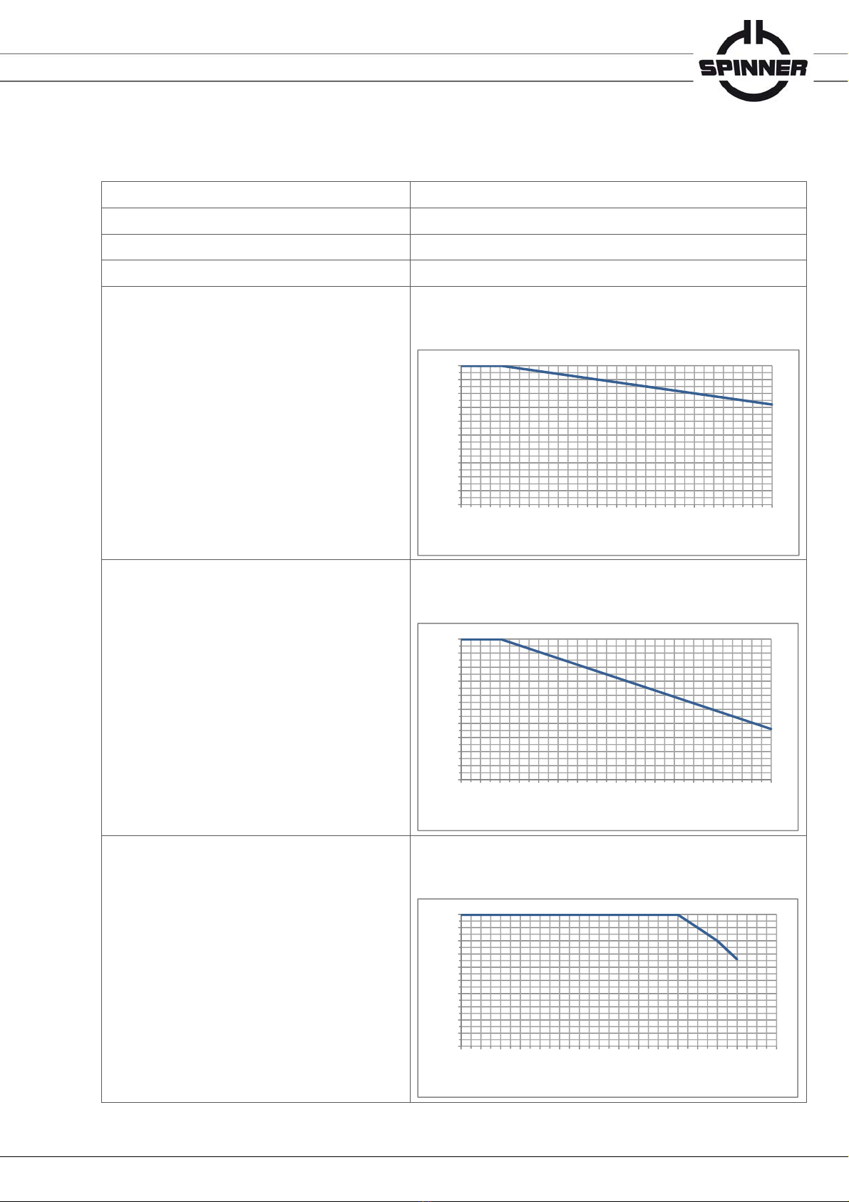
Environmental conditions
Operational conditions ETSI EN 300 019-1-3 V2.3.2 (2009-1) class 3.1 N
Ambient temperature **** -10 to +60°C
Condensation Not allowed
Relative humidity, max. 95%
Derating of input power with increasing altitude
The maximum input power can be applied up to 500 m or 1600 ft above
sea level unless noted otherwise in the data sheet.
Above this height the maximum input power must be reduced as shown in
the diagram.
Derating of voltage with increasing altitude
The maximum voltage can be applied up to 500 m or 1600 ft above sea
level unless noted otherwise in the data sheet.
Above this height the maximum input power must be reduced as shown in
the diagram.
Derating of input power with increasing ambient
temperature
The maximum input power can be applied up to +45°C ambient
temperature unless noted otherwise in the data sheet.
Above this ambient temperature the maximum input power must be
reduced as shown in the diagram.
50%
55%
60%
65%
70%
75%
80%
85%
90%
95%
100%
0 500 1000 1500 2000 2500 3000 3500 4000
Altitude above sea level [m]
50%
55%
60%
65%
70%
75%
80%
85%
90%
95%
100%
0 500 1000 1500 2000 2500 3000 3500 4000
Altitude above sea level [m]
50%
55%
60%
65%
70%
75%
80%
85%
90%
95%
100%
-10 0 10 20 30 40 50 60 70
Ambient temperature [°C]

Data subject to change without notice │M36326 │Issue C
www.spinner-group.com
10 / 18
Max. altitude above sea level 4,000 m or 13,120 ft according to IEC EN 60664-1
Protection class III according to IEC EN 61140
IP protection level IP40 according to IEC EN 60529
(all interfaces equipped with appropriate gaskets)
Installation position Any
Transport conditions ETSI EN 300 019-1-2 V2.1.4 (2003-04) class 2.2
Ambient temperature -25 to +70°C
Rain, condensation, icing Not allowed
Storage conditions ETSI EN 300 019-1-1 V2.1.4 (2003-04) class 1.2
Ambient temperature -10 to +60°C
Rain, condensation, icing Not allowed
* Standard conditions:
Dielectric: Dry air under standard pressure at sea level (p = 1013 hPa)
Load VSWR, max. 1.0 (no standing wave)
No modulation, sinusoidal carrier only
** Suitable mating connector included
*** At room temperature and nominal voltage 24 V DC
**** Extended temperature range on request
Data subject to change without notice │M36326 │Issue C
www.spinner-group.com
11 / 18
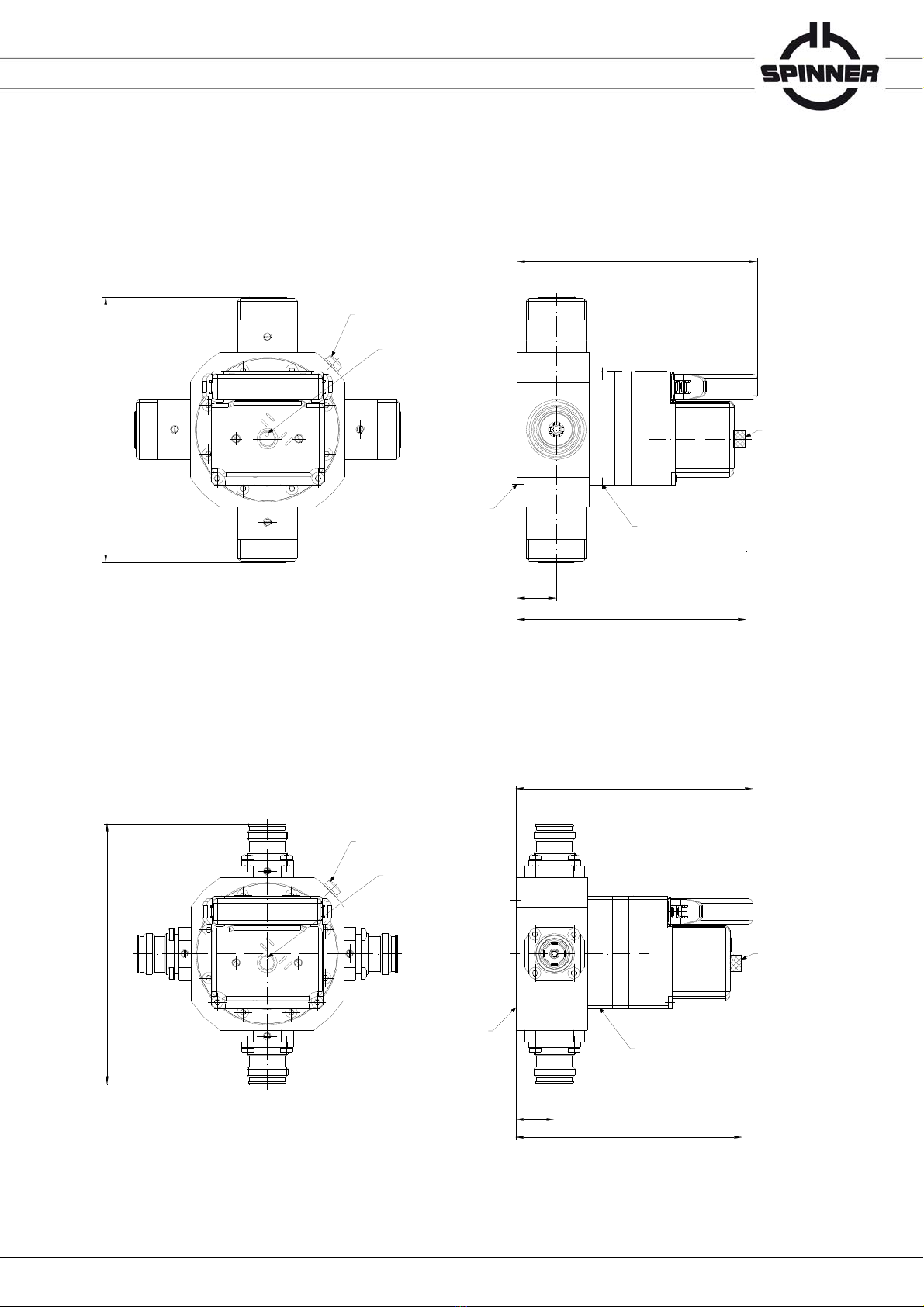
6. Outline (all dimensions in millimeters)
BN 754081:
BN 754082:
(+10 mm to disconnect the connector)
1
2
3
4
RF connection
RF position I: 1-2 / 3-4
RF position II: 1-4 / 2-3
Position indication
128,8±0,5
116,34
111±2
19
Threaded mounting holes
2x M4 / 6 deep on both sides
Ground connection
M4
Manual operation
Threaded mounting holes
4x M4 / 6 deep on Ø75
111
±2
RF connection
RF position I: 1-2 / 3-4
RF position II: 1-4 / 2-3
3
2
1
4
Position indication
Ground connection
M4
Threaded mounting holes
4x M4 / 6 deep on Ø75 Threaded mounting holes
2x M4 / 6 deep on both sides
Manual operation
(+10 mm to disconnect the connector)
116,34
19
128
±0,5

Data subject to change without notice │M36326 │Issue C
www.spinner-group.com
12 / 18
7. Circuit diagram (B24140-CD, Issue D)
Data subject to change without notice │M36326 │Issue C
www.spinner-group.com
13 / 18
8. Storage
Keep dry and avoid exposure to sudden temperature changes to prevent condensation. Environmental
conditions for storage are specified in the data sheet of this manual. Do not unpack until immediately
prior to installation.
ATTENTION Do not remove any connector transportation locks until immediately prior to assembly
to avoid damage.
9. Transportation
Before you start, ensure to read and understand the attached Basic Safety
Instructions and the additional safety instructions on personal safety that appea
r
in relevant parts of this manual.
WARNING
Crushing Hazard
Falling objects may cause death and serious injury.
Use suitable lifting gear and means of transportation.
Secure the cardboard against tipping or falling.
Do not stand below the RF switch.
Safety shoes are required.
CAUTION
Sharp Edges
Sharp edges may cause cuts and needle stick injuries.
Use safety gloves and handle carefully.
10. Installation
Before you start, ensure to read and understand the Basic Safety Instructions and
the additional safety instructions on personal safety that appear in relevant parts of
this manual. Failure to observe could result in death or serious injury. Only trained
electricians should install SPINNER RF switches in accordance with applicable
national and international safety rules and regulations.
WARNING
Radio Frequency Hazard
Radio Frequency Power can cause burns, eye injuries and electric shock.
Before you start, ensure to disconnect your entire system from the power supply.
Utilize appropriate devices and methods to prevent accidental energizing.
WARNING
Crushing Hazard
Falling objects may cause death and serious injury.
Secure the RF switch against tipping or falling until it is securely bolted to the
mounting rack. Safety shoes are required. If it is necessary to stand below the RF
switch during installation, safety shoes and hardhat are required.
Data subject to change without notice │M36326 │Issue C
www.spinner-group.com
14 / 18
CAUTION
Sharp Edges
Sharp edges may cause cuts and needle stick injuries.
Use safety gloves and handle carefully.
A
TTENTION The supplied packaging and all protection caps are reusable and required for
transportation. Do not damage or dispose of the packaging.
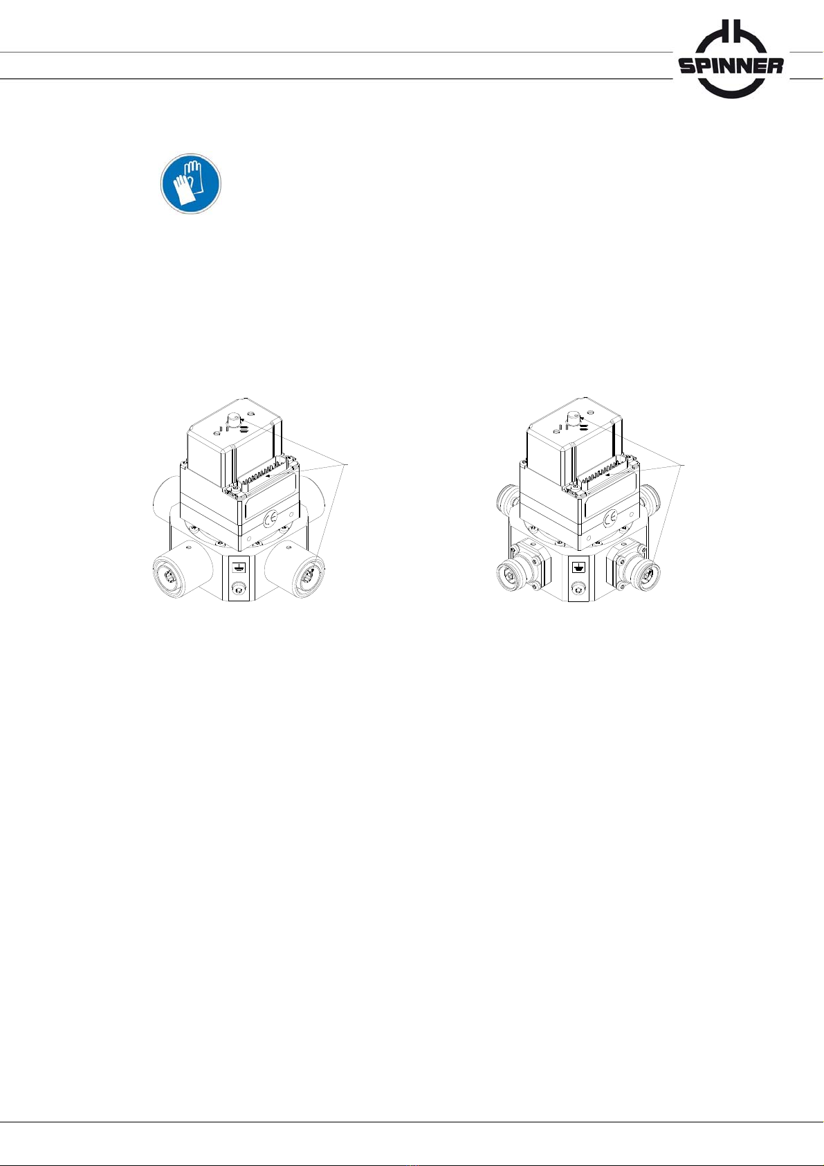
10.1 Mechanical installation
Install the RF switch in indoor applications on operating sites with limited access only. Do not stress
the connectors and the manual override.
Use the fastening threads on the bottom or the lateral fastening threads to bolt the switch securely to
the mounting rack. Do not clamp the RF switch on the casing. Use a torque wrench to tighten the
bolted connections to 1.2 Nm (bolt material A2-50) / 2.5 Nm (bolt material A2-70).
10.2 RF installation
Remove the protection caps.
Align the system connectors carefully with the RF switch to avoid scratches on the contacts.
Remove any dirt or metallic particles on contact surfaces before connecting.
Ensure sufficient strength of all RF connections.
BN 754081 (RF connection 7-16): Torque all connections to 30 Nm.
BN 754082 (RF connection 4.3-10): Torque all connections to 5 Nm.
Unused ports must be terminated.
Relieve all RF connections from any bending torque, e.g. caused by heavy cables or assemblies.
Avoid sharp bends and tensile load.
10.3 Electrical installation
WARNING Do not use the interlock loop for personal protection.
ATTENTION Do not use the interlock loop for operational switch-off of the transmitters. Connect
all transmitters to the interlock loop to avoid RF switch damage. Hot switching is not
permitted.
do not stress
do not stress
Data subject to change without notice │M36326 │Issue C
www.spinner-group.com
15 / 18
Follow the circuit diagram given in this manual and use the supplied connector only to connect
interlock, signal, control and operating voltage.
The interlock and signal contacts comply with the requirements for SELV (DIN EN 60950-1).
The maximum permissible voltage is 42.4 V ACpk / 60 V DC. This applies to the loop voltage and
the voltage between signal or interlock contacts and to the earthed casing. Limit the circuits
externally by means of fuses to 0.5 A.
To ensure equipotential bonding with other plant components, connect the marked earthing
terminal to the main earthing busbar with a copper lead (min 6 mm²).
Use a suitable and amply dimensioned power cord (min AWG 24, max AWG 20) and the supplied
25 pole connector BN 122886 for the electrical connecting. Limit the operating current by means of
an external fuse (time-delay, 2 A).
Relieve all connections to the RF switch from any bending torque, e.g. caused by heavy cables or
assemblies. Avoid sharp bends and tensile load.
11. Commissioning
Before you start, ensure to read and understand the Basic Safety Instructions and
the additional safety instructions on personal safety that appear in relevant parts of
this manual. Failure to observe could result in death or serious injury. Only trained
electricians should commission SPINNER RF switches.
WARNING
Radio Frequency Hazard
Radio Frequency Power can cause burns, eye injuries and electric shock.
Check sufficient strength of all RF connections prior to commissioning.
Unused ports must be terminated. Check proper functioning of the interlock loop
prior to commissioning.
12. Operation
CAUTION
Hot surface
The RF switch heats up during normal operation. Touching it may cause burns.
Do not touch the RF switch while hot. Wait until completely cooled off.
The operator must control the access to the hazardous area.
A
TTENTION Switch off all transmitters before actuating the RF switch to avoid RF switch damage.
Hot switching is not permitted.
A
TTENTION Do not block the manual override during electrical switching to avoid overheating and
RF switch damage.
A
TTENTION Do not place any heat-generating devices such as radiators or fan heaters near to the
RF switch to avoid overheating and RF switch damage.
13. Cleaning
Periodic cleaning of the mounted RF switch is not required. Use a soft, but not damp duster, if cleaning
of the demounted RF switch is required. Do not use compressed air.

Data subject to change without notice │M36326 │Issue C
www.spinner-group.com
16 / 18
CAUTION
Hot surface
The RF switch heats up during normal operation. Touching it may cause burns.
Do not touch the RF switch while hot. Wait until completely cooled off.
The operator must control the access to the hazardous area.
A
TTENTION Do not use any cleaning fluid to avoid the risk of serious injury at re-commissioning.
14. Maintenance
Periodic maintenance is not required. Carry out at least one switching cycle annually to avoid jamming.
If the switch was not actuated for a period longer than one year (e.g. storage) carry out several
switching cycles before applying RF power.
15. Repairs
Repairs may only be executed by the manufacturer or technical personnel authorized by the
manufacturer.
CAUTION
Hot surface
The RF switch heats up during normal operation. Touching it may cause burns.
Do not touch the RF switch while hot. Wait until completely cooled off.
Do not open the RF switch to avoid the risk of high-frequency radiation and serious
injury.
16. Warranty
Do not disassemble the RF switch. The warranty is void, if the RF switch is modified, improperly
handled or third party intervention or modification has occurred.
17. Demounting
Before you start, ensure to read and understand the Basic Safety Instructions and
the additional safety instructions on personal safety that appear in relevant parts of
this manual. Failure to observe could result in death or serious injury. Only trained
electricians should demount SPINNER RF switches.
WARNING
Radio Frequency Hazard
Radio Frequency Power can cause burns, eye injuries and electric shock.
Before you start, ensure to disconnect your entire system from the power supply.
Utilize appropriate devices and methods to prevent accidental energizing.
Data subject to change without notice │M36326 │Issue C
www.spinner-group.com
17 / 18
CAUTION
Hot surface
The RF switch heats up during normal operation. Touching it may cause burns.
Do not touch the RF switch while hot. Wait until completely cooled off.
WARNING
Crushing Hazard
Falling objects may cause death and serious injury.
Secure the RF switch against tipping or falling. Safety shoes are required. If it is
necessary to stand below the RF switch during demounting, safety shoes and
hardhat are required.
CAUTION
Sharp Edges
Sharp edges may cause cuts and needle stick injuries.
Use safety gloves and handle carefully.
A
TTENTION The supplied packaging and all protection caps are reusable and required for
transportation. If not available, contact SPINNER before starting demounting.
Do not stress the connectors and the manual override.
Follow the procedure described in chapter 10 in reverse order.
18. Disposal
The user is responsible for disposing of the RF switch in accordance with the national
waste disposal regulations. Improper disassembly or disposal may be hazardous!
19. Additional endangering (regardless to life cycle)
WARNING
Lightning Hazard
Lightning may cause electric shock, burns and serious injury.
Use suitable overvoltage protection to ensure that no overvoltage (such as that caused
by a bolt of lightning) can reach the product. Use a copper lead (min 6 mm²) to connect
the marked earthing terminal to the main earthing busbar.

Data subject to change without notice │M36326 │Issue C
www.spinner-group.com
18 / 18
20. Environmental friendly usage period
表1有害物质名称及含量标识格式
Table1MarkingStylesfortheNamesandContentsoftheHazardousSubstances
Part Name
部件名称
Hazardous Substances
有害物质
Lead
(Pb)
铅
Mercury
(Hg)
汞
Cadmium
(Cd)
镉
Hexavalent
Chromium
(Cr(VI))
六价铬
Polybrominated
biphenyls
(PBB)
多溴联苯
Polybrominated
diphenyl ethers
(PBDE)
多溴二苯醚
Metal parts
金属零件 X O O O O O
This table is prepared in accordance with the provisions of SJ/T 11364.
本表格依据 SJ/T 11364 的规定编制。
O:Indicates that said hazardous substance contained in all of the homogeneous materials for this part is below the
limit requirements of GB/T 26572.
O:表示该有害物质在该部件所有均质材料中的含量均在 GB/T 26572 规定的限量要求以下。
X:Indicates that said hazardous substance contained in at least one of the homogeneous materials used for this
part is above the limit requirements of GB/T 26572.
(Enterprises may further provide in this box technical explanation for marking ”X” based on their actual
circumstances.)
X:表示该有害物质至少在该部件的某一均质材料中的含量超出 GB/T 26572 规定的限量要求。
(企业可在此处,根据实际情况对上表中打“X”的技术原因进行进一步说明。)
21. Spare parts
22. Contacts
SPINNER GmbH • Headquarters
Erzgiessereistr. 33
80335 München
Germany
Phone +49 8912601-0
Web: www.spinner-group.com
Spinner Telecommunication Devices (Shanghai) Co., Ltd
351 Lian Yang Road
Songjiang Industrial Zone
Shanghai 201613
China
Phone +86 21 5774 5377
Web: www.spcn.cn
Designation Order-No. Qty.
Cable connector (J1, 25 pole) for operating voltage,
control, interlock contacts and signaling BN 122886 1
This manual suits for next models
1
Table of contents
Popular Switch manuals by other brands


MiLAN
MiLAN MIL-SM2401M-STK user guide

ABB
ABB MNS-Up Service manual

IMC Networks
IMC Networks iMcV-FiberLinX-II Operation manual

Spinner
Spinner BN 553064 product manual

Siemens
Siemens RUGGEDCOM RS8000H installation guide

Brocade Communications Systems
Brocade Communications Systems FastIron SX 800 Diagnostic manual


