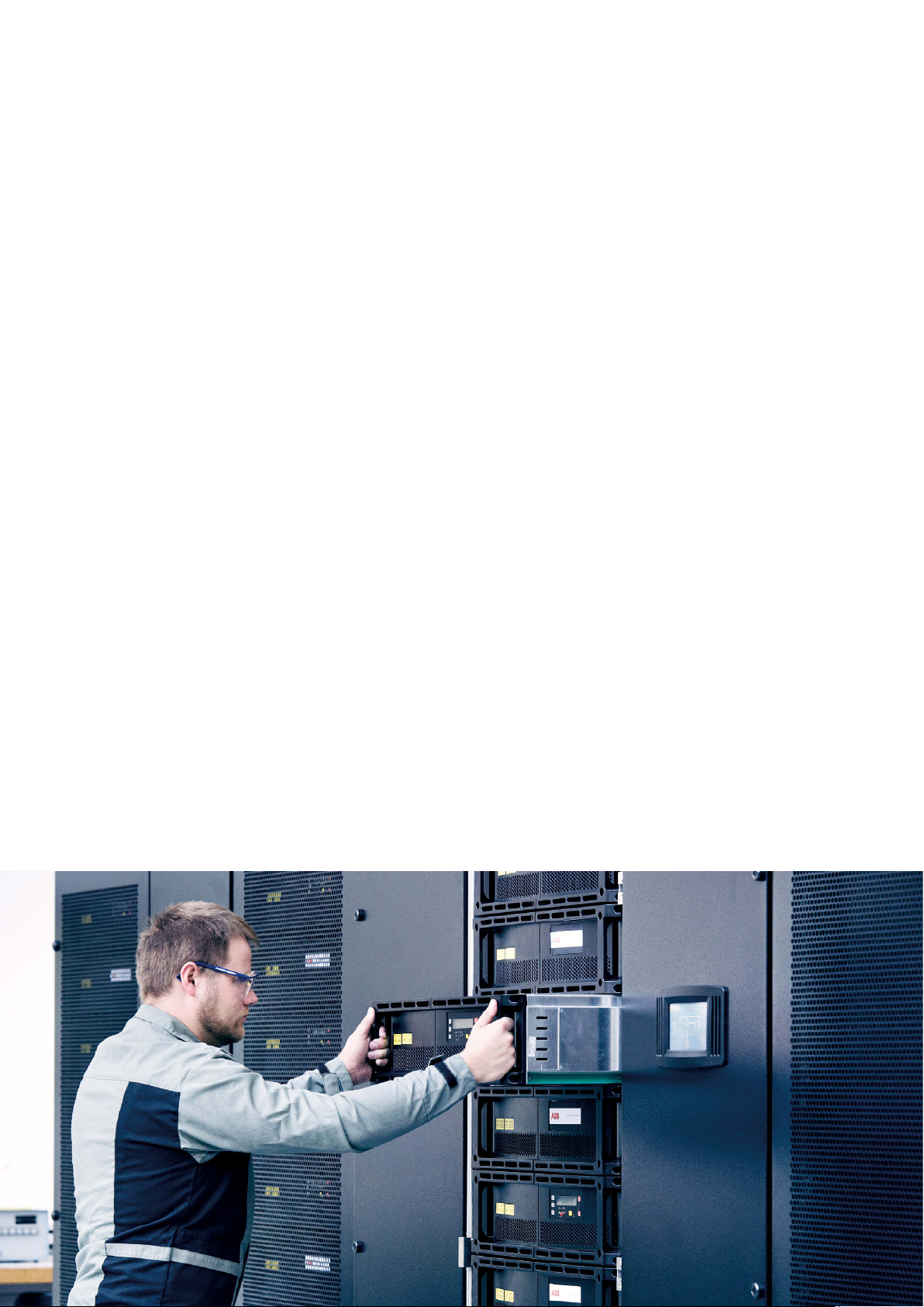
10 MNS-UP SERVICE MANUAL
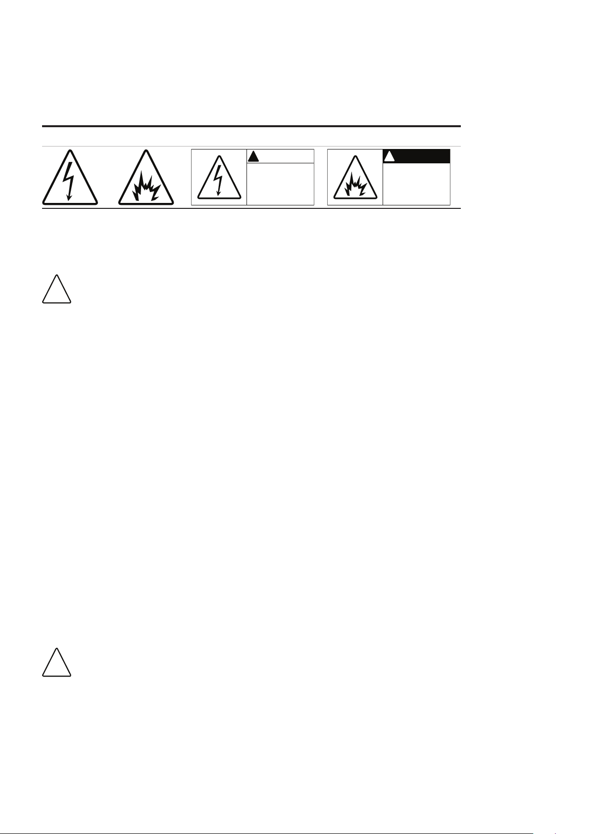
2.3 Warning signs and labels
Electrical systems shall be labeled according to the hazard risk level. ISO3864 and its ANSI equivalent Z535.4 prescribes the
layout and application of signs. Following sings are typically applied:
High Voltage
ISO3864
Arc Flash Hazard
ISO3864
Warning Sign
ANSI Z535.4
Danger Sign
ANSI Z535.4
ARC FLASH and
SHOCK HAZARD
Appropriate PPE and
Tools required when
working on thi
equipment
!
Arc Flash Hazard
Follow requirements for
safe work practices and
apporopriate PPE.
Failure to comply can
result in death or injury.
!
Table 2-01 Typical warning signs and labels
2.4 Basic principles and precautions to be observed
In accordance with the valid local regulations, all installation and maintenance work involving MNS low voltage
switchgear systems may only be performed by skilled and qualified personnel. For work at low voltage electrical
system and components, the component to be modified or worked on must be isolated and confirmed dead.
If in doubt of the task to be carried out, ABB Service technicians should be utilized for the work. Never utilize
untrained personnel who are not certified with the system.
The mandatory guideline for working in electrical systems is the instruction EN50110-1 2013. Local country law for work on
electrical systems must also be observed. Minimum precautions are to be observed:
• THINK – The greatest safety asset is an alert, focused mind,
• Maintain strict discipline regarding safety procedures,
• Use appropriate personnel protection equipment and tools,
• Communicate clearly and ensure all communications are fully understood,
• Query all instructions that are unclear, not understood or that appear to be in breach of safety requirements,
• Prove all circuits to be safe if they have been unattended for a period of time,
• Maintain safety clearance (air Insulation) when working in the proximity of live conductors,
• Do not improvise. Use purpose designed equipment and tools,
• Use the pre-start checklist prior to starting or commencing any work.
2.5 Areas of work
Working on electrical systems may occur at different times and different conditions. To clearly understand the conditions
helps to understand and eliminate any risk. In low voltage switchgear systems following work conditions are defined:
• Operation (operation of circuit breaker, main switch or push button while all doors and compartments are closed – closed
door condition)
• Visual inspection (open doors and compartments to perform any visual inspection, no parts are touched and no physical
work is performed on the electrical system – open door condition)
• Any other maintenance and work (e.g. modification, extensions, cable connection) on low voltage electrical system (either
open or closed door condition)
The procedure for performing switching operations is defined by the instruction EN50110-1 2013 “Operation of electrical
installations”.
Keep doors and covers closed & locked whenever possible.
Check if lock couplings are utilised otherwise, each lock must be locked.