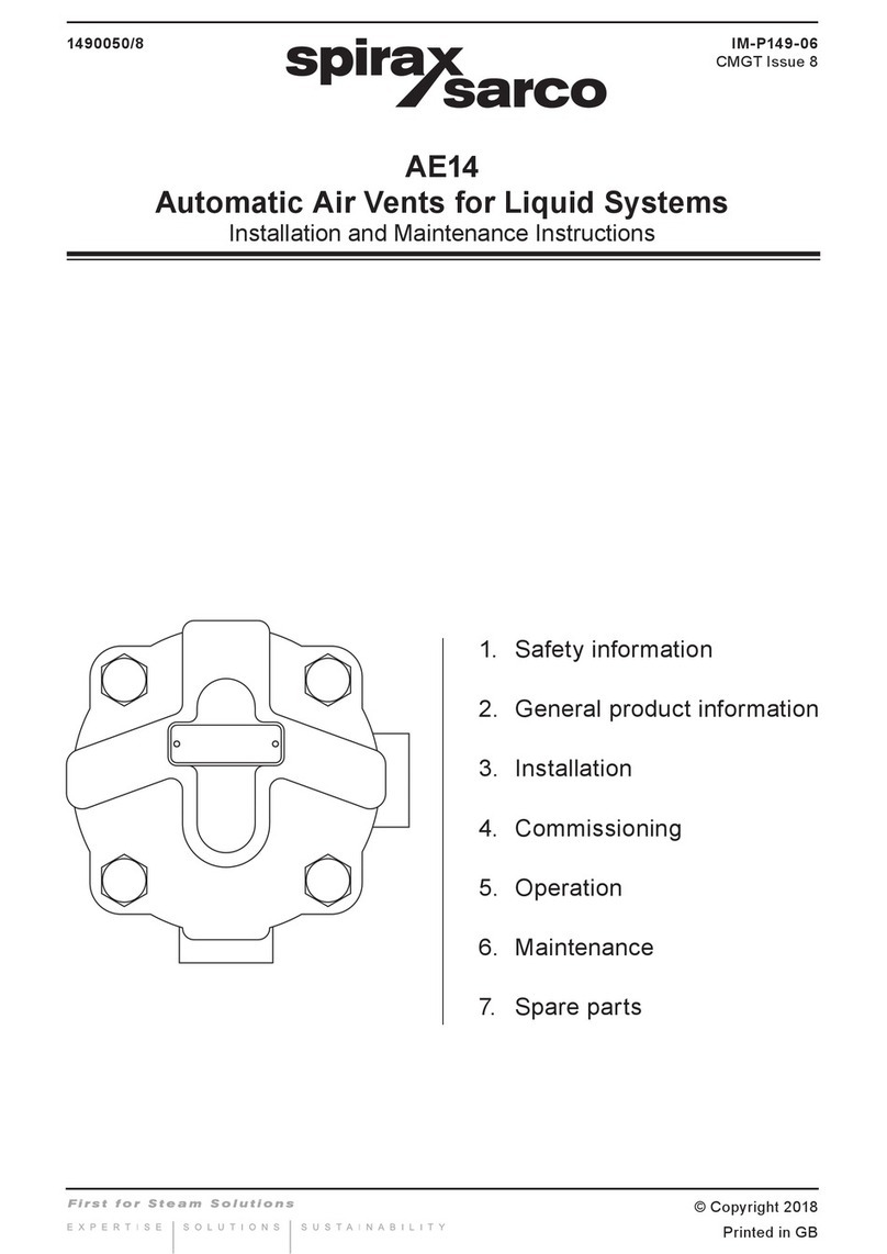
Spirax Sarco AE36 User manual

IM-P017-03 ST Issue 5 1
AE36andAE36A
Automatic Air Eliminators/AirVents for Liquid Systems
Installation and Maintenance Instructions
IM-P017-03
ST Issue 5
0170550/5
1. General
safety information
2. General
product information
3. Installation
4. Commissioning
5. Operation
6. Maintenance
7. Spare parts
Printed in the UK © Copyright 2004

IM-P017-03 ST Issue 52
1. General safety information
Safe operation of the unit can only be guaranteed if it is properly installed,
commissioned and maintained by a qualified person (see Section 11 of the attached
Supplementary Safety Information) in compliance with the operating instructions.
General installation and safety instructions for pipeline and plant construction, as
well as the proper use of tools and safety equipment must also be complied with.
Isolation
Consider whether closing isolating valves will put any other part of the system or
personnel at risk. Dangers might include; isolation of vents and protective devices or
alarms. Ensure isolation valves are turned off in a gradual way to avoid system shocks.
Pressure
Before attempting any maintenance consider what is or may have been in the pipeline.
Ensure that any pressure is isolated and safely vented to atmospheric pressure before
attempting to maintain the product, this is easily achieved by fitting Spirax Sarco
depressurisation valves type DV (see separate literature for details). Do not assume
that the system is depressurised even when a pressure gauge indicates zero.
Temperature
Allow time for temperature to normalise after isolation to avoid the danger of burns and
consider whether protective clothing (including safety glasses) is required.
Viton 'O' ring:
If the Viton 'O' ring has been subjected to a temperature approaching 315°C (599°F) or
higher, it may have decomposed and formed hydrofluoric acid. Avoid skin contact and
inhalation of any fumes as the acid will cause deep skin burns and damage the respiratory
system.
Disposal
The product is recyclable. No ecological hazard is anticipated with the disposal of this
product providing due care is taken, EXCEPT:
Viton:
-Wastepartscanbelandfilled,whenincompliancewithNationalandLocalregulations.
-Waste parts can be incinerated, but a scrubber must be used to remove Hydrogen
Fluoride, which is evolved from the product and with compliance to National and
Local regulations.
-Is insoluble in aquatic media.

IM-P017-03 ST Issue 5 3
2. General product information
2.1 General description
The AE36 range of automatic air eliminators/air vents are designed for use on hot and cold water
installations. The body and cap are of austenitic stainless steel type 316L.
They are available as follows:
AE36 Standard air vent
AE36A Standard air vent with check valve
Note: For further information see the following Technical Information Sheet, TI-P017-02.
2.2 Sizes and pipe connections
Inlet ½" female BSP or NPT
Outlet ¼" male BSP or NPT
Fig. 1 AE36A shown
Check valve

IM-P017-03 ST Issue 54
2.3 Pressure/temperature limits
Temperature °C
Pressure bar g
150
110
100
50
0
0123456789
10
-10
0100
300
200
20 40 60 80 120 140
100
14
The product should not be used in this region as damage to the internals may occur.
Body design conditions PN10
PMA Maximum allowable pressure 10 bar g @ 150°C (145 psi g @ 302°F)
TMA Maximum allowable temperature 150°C (302°F)
Minimum allowable temperature -10°C(14°F)
PMO Maximum operating pressure 10 bar g @ 110°C (145 psi g @ 230°F)
TMO Maximum operating temperature 110°C @ 10 bar g (230°F @ 145 psi g)
Minimum operating temperature -10°C(14°F)
DPMX Maximum differential pressure 8 bar (116 psi)
Designed for a maximum cold hydraulic test pressure of: 15 bar g (217.5 psi g)
Minimum specific gravity of liquid 0.926
Pressure psi g
Temperature °F

IM-P017-03 ST Issue 5 5
3. Installation
Note: Before actioning any installation observe the 'Safety information' in Section 1.
Referring to the Installation and Maintenance Instructions, name-plate and Technical Information
Sheet, check that the product is suitable for the intended installation:
3.1 Check materials, pressure and temperature and their maximum values. If the maximum
operating limit of the product is lower than that of the system in which it is being fitted,
ensure that a safety device is included in the system to prevent overpressurisation.
3.2 Determine the correct installation situation and the direction of fluid flow.
3.3 Remove protective covers from all connections.
3.4 Theautomaticaireliminator/airventshouldbeinstalledverticallywiththeinletatthebottom.
We recommended that a drip pipe be fitted discharging to a safe place. To enable this to
be done the outlet is provided with a ¼" BSP or NPT male thread. See Fig. 2 for a typical
application.
Discharge to
safe visual point
Air bottle
Fig. 2 Typical application
The automatic air eliminator/air vent should be installed
verticallywiththeinletatthebottom.Werecommendpiping
the discharge from the air eliminator/air vent to a suitable
safe point.

IM-P017-03 ST Issue 56
Note: Before actioning any maintenance program observe
the 'Safety information' in Section 1.
6.1 General information
All work must be carried out by a suitably competent person. Before starting work ensure that
suitable tools are available. Use only Spirax Sarco replacement parts. Before attempting to
workontheairventensurethatitisisolatedfromtherestofthepressurisedsystem.Allowtime
for the temperature of the air vent to normalise.
The unit has a long service life and the only maintenance that would normally be required is
the occasional cleaning of the valve and seat.
6.2 How to clean/replace the valve and seat:
-Unscrew the cap (1) from the body.
-The float(4)can then be detached from the lever and the mechanism removed by undoing
the screw (8) in the centre of the cap.
-The valve cone (5) is easily changed once the float has been removed.
-Refitting of the mechanism is straight forward, the float can then be hooked back onto the
lever and the whole assembly screwed back into the body (see Table 1 for recommended
tightening torques).
-The set of internals are supplied with a check valve ball and circlip.
-The check valve is only required for the AE36A.
-The check valve should be fitted into the outlet port and held loosely by the circlip, which
is fitted 1.6 mm below the level of the outlet as shown in Fig. 3.
After maintenance ensure that the system is fully functioning.
6. Maintenance
After installation or maintenance ensure that the system is fully functional. Carry out tests on
any alarms or protective devices.
4. Commissioning
At start-up the air eliminator/air vent is open allowing air to pass through the main valve. As
soon as water reaches the vent the float is raised and the lever mechanism closes the valve.
When more air reaches the vent it displaces water and the float falls thus opening the valve.
After the air is discharged the valve is closed, as the water level rises to replace the air.
Thecheck valve (AE36A)is essentialwherethere isapossibilityofthesystemoperatingunder
negative head conditions. It will prevent air being drawn into the system.
5. Operation
Fig. 3
1.6 mm

IM-P017-03 ST Issue 5 7
Table 1 Recommended tightening torques
or
Item N m (lbf ft)
mm
130 10 - 12 (7.0 - 8.6)
8Cheesehead M4 x 6 2.5 - 2.8 (1.8 - 2.0)
Fig. 4
1
8
4
5
AE36A only

IM-P017-03 ST Issue 58
The spare parts available are shown in heavy outline. Parts drawn in broken lines are not
supplied as spares.
Available spares
Maintenance kit comprising:
Cap 'O' ring, float, valve cone, check valve ball, check valve circlip 2, 4, 5, 9, 10
Important note
If you have earlier versions of the AE36 designated AE36CV which operate over the
range 3 to 8 bar then the spares set for the AE36A cannot be used. The earlier spares set should
be used.
How to order spares
Always order spares by using the description given in the column headed 'Available spares' and
state the size and type of automatic air vent.
Example: 1 - Maintenance kit for a Spirax Sarco ½" AE36A automatic air eliminator/air vent with
check valve.
7. Spare parts
Fig. 5
5
4
2
10
9AE36A only
This manual suits for next models
1
Table of contents
Other Spirax Sarco Fan manuals
Popular Fan manuals by other brands

NORDICCO
NORDICCO NORTHERN LIGHT Installation manual & users guide

Flexit
Flexit BR100 User and installation manual

Cairox
Cairox ETAMASTER 150L EC 01 Assembly instruction

QuietCool
QuietCool STEALTH PRO-1.5X owner's guide

Monte Carlo Fan Company
Monte Carlo Fan Company Jovie 3JVR58 Series Owner's guide and installation manual

Helios
Helios KWL 360 W Installation and operating instructions