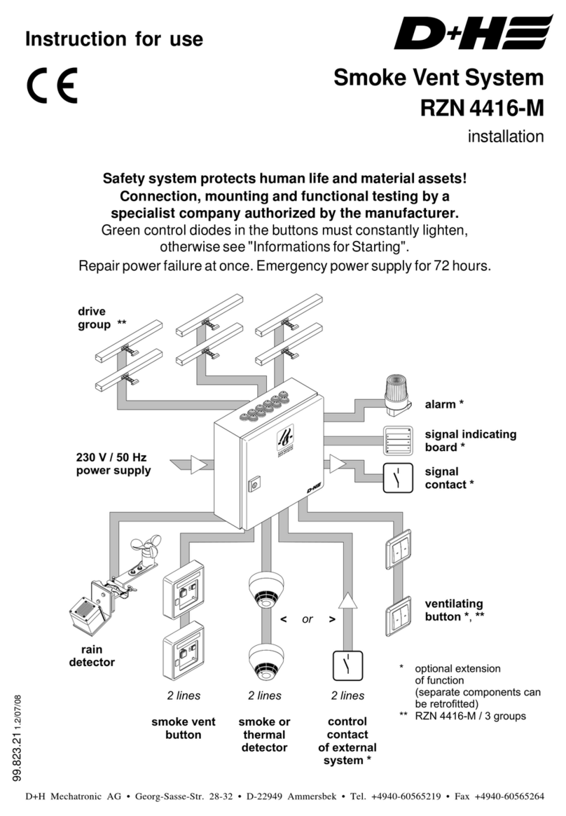
D+H BlueKit AIO Basic User manual

AIO Basic
99.829.07 1.2/06/23
Bluekit Downloads
en Original instructions
Product overview and mounting . . . . . . . . . . . . . . Page. . . . . 3-19
Connection and setup. . . . . . . . . . . . . . . . . . . . . . Page. . . . 20-25
Maintenance. . . . . . . . . . . . . . . . . . . . . . . . . . . . . Page. . . . 26-29
Troubleshooting . . . . . . . . . . . . . . . . . . . . . . . . . . Page. . . . 30-36
Mounting material. . . . . . . . . . . . . . . . . . . . . . . . . Page . . . . . . 37

3/402/40
Table of contents
Intended use
- The AIO basic system is used in lift shafts to detect
fires with developing smoke and for ventilation.
- Only for inside mounting
Operating voltage 230 V AC!
Risk of injury from electric shock!
- Connection has to be carried out only by an
authorized electrical specialist
- Only for inside mounting
- Just use unchanged original D+H parts
Caution Falling Hazard!
- Always secure ventilation elements properly
against falling down the shaft.
The following protective equipment must be worn:
- Hard hat
- Safety goggles
- Safety shoes
- Full-body safety harness
- Protective gloves
- Hearing protection
Safety notes
Application example
1
Control unit(CPL-B)
2
Ventilation flap (JK)
with spring return motor
3
Smoke detector in the lift shaft
4
Lift Status Transmitter (LST-CO2)
5
Smoke vent button (RT-45L-RJ / RT-45-RJ)
6
Smoke detector at main evacuation level
7
Connection to lift controller
Notice:
The system here has not been illustrated with all
available components.
If available, install the timer and thermostat in the
vicinity of the central unit.
Install the key switch in coordination with the
operator.
Product overview and mounting
Intended use .............................................................................................................................................3
Safety notes ..............................................................................................................................................3
Application example..................................................................................................................................3
System components overview ..................................................................................................................4
System components description ...............................................................................................................5
Overview control panel - CPL-B................................................................................................................6
LED indicators- CPL-B..............................................................................................................................7
RJ45 connections and status LEDs ..........................................................................................................7
DIP switch settings - CPL-B......................................................................................................................8
Technical Data - CPL-B.............................................................................................................................9
Declaration of Conformity .........................................................................................................................9
Service timer .............................................................................................................................................9
Important regulations ................................................................................................................................9
Mounting - Weather protection HVC, HVL, ALAS ...................................................................................10
Mounting - Ventilation flap JK 180, JK 190 ........................................................................................10-11
Mounting - Control unit CPL-B ................................................................................................................12
Mounting - Point detector in the lift shaft PD-RJ-AIO..............................................................................12
Mounting - Infrared detector SD-L-F1 .....................................................................................................13
Initialisation - SD-L-F1 ............................................................................................................................14
Mounting - Smoke vent button RT 45-L-RJ / RT 45-RJ ..........................................................................15
Mounting - Lift Status Transmitter LST-CO2 ...........................................................................................16
DIP switch settings - LST-CO2 ...............................................................................................................17
Technical Data - LST-CO2 ......................................................................................................................18
Initialisation - LST-CO2 ...........................................................................................................................18
Identifying a lift fault with trapped persons .............................................................................................19
Connection and setup
Mounting - Lift Status Repeater LSR ......................................................................................................19
Connection - RJ45 sockets .....................................................................................................................20
Connection - 230 V power supply ...........................................................................................................21
Connection - M1 output...........................................................................................................................21
Connection - General status signals COM 1...........................................................................................22
Connection - Lift shaft control COM 2.....................................................................................................23
Connection - FAS input ...........................................................................................................................24
Blower Door Test.....................................................................................................................................25
Disposal ..................................................................................................................................................25
Maintenance
Maintenance and cleaning ......................................................................................................................26
Maintenance mode / Alarm Reset - CPL-B .............................................................................................26
Status indicators (maintenance level 1) ..................................................................................................27
Function test - Ventilation elements JK-180 / JK-190 .............................................................................27
Function test - Smoke detector SD-L-F1 ................................................................................................28
Function test - Smoke detector PD-RJ-AIO ............................................................................................28
Function test - Lift Status Transmitter LST-CO2 .....................................................................................29
Function test - Smoke vent button RT 45-RJ ..........................................................................................29
Troubleshooting
Troubleshooting - Internal fault indicators ...............................................................................................30
Troubleshooting - Alarm signal SD-L-F1 (set point function) ..................................................................30
Troubleshooting - External fault indicators..............................................................................................31
Troubleshooting - Ventilation element does not close .......................................................................32-33
Troubleshooting - Ventilation element does not open .............................................................................34
Troubleshooting - Malfunction of the LST-CO2 ......................................................................................35
Troubleshooting - LSR malfunction.........................................................................................................36
Mounting material
Mounting material ...................................................................................................................................37
Notes .................................................................................................................................................38-39
99.829.07 1.2/06/2399.829.07 1.2/06/23
AIO Basic AIO Basic
English English
WARNING
Read all safety warnings, instructions, illustrations
and specifications provided with this product.
Failure to follow all instructions listed below may
result in electric shock, fire and/or serious injury.
Save all warnings and instructions for future
reference.

4/40 5/40
System components overview
HVLHVC
JK-180 ALAS
JK-190
RT 45/O-L-RJ
RT 45/O-RJLSR
LST-CO2
SD-L-F1
PD-RJ-AIO-HE
CPL-B
TS-RJ SLT 42-U-SD-RJ CWSO-RR-S1-RJRTR 231-RJ
PD-RJ-AIO-P&G
PD-RJ-AIO-End
1. 2.
4.
5.
6.
7.
3.
System components description
1. Ventilation flap (SHEV)
• Cutting back on energy losses thanks to closure of the opening in the lift shaft.
• Ventilates and extracts smoke when necessary.
• For vertical or horizontal installation.
• Depending on the building type, with or without weather protection
JK-180 - Ventilation flap with spring return motor with mounting frame for integrated installation
JK-190 - Ventilation flap with spring return motor for surface mounting
2. Weather protection
HVC - Weather protection roof cover for horizontal installation
HVL - Louvre cover for horizontal installation
ALAS - Weather protection grille for vertical installation
3. Smoke detection
• Smoke detection throughout the lift shaft height and signal transmission to the central unit.
• Two options: Point-type smoke detectors or infrared detectors (SD-L-F1).
• Choice dependent on shaft dimensions and building requirements.
PD-RJ-AIO-P&G - Optical smoke detector (up to 36 m shaft height)
PD-RJ-AIO-End - Optical smoke detector with integrated terminal resistor
SD-L-F1 - Infrared smoke detector (up to 100 m shaft height)
4. Central unit
• Receiving and transmitting the trigger signal to open the ventilation flap.
• Central unit with integrated temperature sensor and extended connection options.
CPL-B - Central unit with integrated radio receiver
5. Lift Status Transmitter
• Checking the CO level directly at the lift car.
2
• Additional monitoring of movements or emergency situations in the lift.
• If needed, ventilation signal to the central unit.
• Integrated temperature sensor, humidity sensor, CO sensor and acceleration sensor.
2
• Time-controlled and use-dependent ventilation functions.
• Wireless radio link to the central unit.
LST-CO2 - Lift Status Transmitter
LSR - Lift Status Repeater
6. Smoke vent button with status indicators
• Manual triggering of a ventilation or smoke extraction command and system status display.
• LED Status display depending on model option: ventilation, alarm and fault
RT 45/O-L-RJ - Smoke vent button
RT 45/O-RJ - moke vent button with integrated ventilation button
PD-RJ-AIO-End - optical fire detector for the main evacuation level
7. Additional components
TS-RJ - Timer
SLT 42-U-SD-RJ - Key-operated vent switch
RTR 231-RJ - Room temperature control
CWSO-RR-S1-RJ - Acoustical signal transmitter
99.829.07 1.2/06/2399.829.07 1.2/06/23
AIO Basic AIO Basic
English English

6/40 7/40
Overview control panel - CPL-B
DIP switch
S1 S2
Mains
connection
Reset button with
transport lock
Antenna
Temperature sensor Connections via RJ45 plugs
with LED Status indicators
LED indicators
(internal)
Button
Reset line
ON/OFF
Teach
button
Signal
emitter
Spare fuse in cover
F0,63 A
Fuse
drive
F0,63 A
Fuse
24 V output
F0,315 A
Release opening
for mains plug
LED indicators- CPL-B
LED 1
Radio communication
LED 2
CPU fault CPL-B (yellow)
LED 3
CPL-B OK (green)
LED 4
LST-VOC fault (yellow)
LED 5
Service timer (yellow)
LED 6
Mains (green)
1 2 3 4 5 6
RJ45 connections and status LEDs
COM 2
ADD
COM 1
RT
AL
SD
24 V
M1
LED FAS alarm (ext. alarm)
LED Alarm smoke detector
Connection smoke detector
LED Smoke detector fault
LED FAS fault (ext. alarm)
FAS connection (ext. alarm)
LED smoke detector
Alarm
main evacuation level
LED Earth fault
Signalling input/output 1
LED Temperature CPL-B
LED General fault
Signalling input/output 2
not used
not used
LSR connection
LED Alarm Smoke vent button
Connection smoke vent button
LED Smoke vent button fault
LED Ventilation alarm/fault LST-CO2
Connection for further components
LED Automatic ventilation LST-CO2
LED Ventilation element OPEN
Connection spring return motor
LED Drive group fault
99.829.07 1.2/06/2399.829.07 1.2/06/23
AIO Basic AIO Basic
English English

6/40 7/40
Overview control panel - CPL-B
DIP switch
S1 S2
Mains
connection
Reset button with
transport lock
Antenna
Temperature sensor Connections via RJ45 plugs
with LED Status indicators
LED indicators
(internal)
Button
Reset line
ON/OFF
Teach
button
Signal
emitter
Spare fuse in cover
F0,63 A
Fuse
drive
F0,63 A
Fuse
24 V output
F0,315 A
Release opening
for mains plug
LED indicators- CPL-B
LED 1
Radio communication
LED 2
CPU fault CPL-B (yellow)
LED 3
CPL-B OK (green)
LED 4
LST-VOC fault (yellow)
LED 5
Service timer (yellow)
LED 6
Mains (green)
1 2 3 4 5 6
RJ45 connections and status LEDs
COM 2
ADD
COM 1
RT
AL
SD
24 V
M1
LED FAS alarm (ext. alarm)
LED Alarm smoke detector
Connection smoke detector
LED Smoke detector fault
LED FAS fault (ext. alarm)
FAS connection (ext. alarm)
LED smoke detector
Alarm
main evacuation level
LED Earth fault
Signalling input/output 1
LED Temperature CPL-B
LED General fault
Signalling input/output 2
not used
not used
LSR connection
LED Alarm Smoke vent button
Connection smoke vent button
LED Smoke vent button fault
LED Ventilation alarm/fault LST-CO2
Connection for further components
LED Automatic ventilation LST-CO2
LED Ventilation element OPEN
Connection spring return motor
LED Drive group fault
99.829.07 1.2/06/2399.829.07 1.2/06/23
AIO Basic AIO Basic
English English

8/40 9/40
DIP switch settings - CPL-B
DIP switch S1
Factory
setting
S1.1
Alarm delay, shaft group (60 s)
OFF
S1.2
Shaft group: Ventilation time limitation
OFF
S1.3
Shaft group: Group fault = alarm
OFF
S1.4
Line port 1 shaft detector: Active
ON
S1.5
Port 2 FAS: Active
OFF
S1.6
Button: Active
ON
S1.7
Line fault = alarm
OFF
S1.8
Service timer: ON / OFF (486 days)
Service timer is activated as soon as it is switched from
OFF state (min. 3 sec. duration) to ON.
ON
S1
Factory settings
DIP switch S2
Factory
setting
Normally closed contact signalling relay -
fault message at RJ45 socket COM 1
S2.1
S2.2
Free / OFF
OFF
OFF
Fault in shaft detector and fault group M1
ON
OFF
LST fault
OFF
ON
General fault
ON
ON
X
S2.6
Internal temperature sensor: trigger temperature fault at all lines at 72°C
ON
S2.7
Temperature-dependent ventilation: ON/OFF
ON
S2.8
Temperature sensor: Ventilation threshold: OFF= ca. 30°C/ON = ca. 35°C
OFF
Signalling relay normally open contact/normally
closed contact - fault/alarm at RJ45 socket COM 2
S2.3
S2.4
S2.5
General malfunction (normally closed contact)
OFF
OFF
OFF
X
Shaft fault: (NC contact) line or group
ON
OFF
OFF
RT fault: (normally closed contact)
OFF
ON
OFF
Not assigned
ON
ON
OFF
General fault (normally open contact)
OFF
OFF
ON
Line alarm: (Normally open contact) shaft
ON
OFF
ON
Alarm: (Normally open contact) stairwell
OFF
ON
ON
Not assigned
ON
ON
ON
S2
Factory settings
Technical Data - CPL-B
Type
CPL-B
Power supply
Rated power
Stand-by operating
230 V AC, 50 Hz (195 ... 253 V AC)
55 VA
< 20 VA
Output voltage
Ripple
24 V DC
<0,5 Vpp; < 1%, load-dependent
Monitoring:
Output current
Mode of operation
200 mA
Continuous duty
Alarm / Ventilation:
Output current
Mode of operation
700 mA
Short-time duty, 30% ED
Number of lines / groups*
Fire detectors per line
SHEV buttons per line
Line voltage
1/1
max. 14 pcs.
max. 8 pcs.
15 V DC (12 ... 17 V DC)
Temperature range
Ingress protection
Protection class
-5 ... +40°C
IP 30
II, with fuctional ground
Housing:
Material
Colour
Dimensions WxHxD
Plastic (Polycarbonate)
white
172 x 151 x 95 mm
* D+H Highspeed (HS) drives will be supported.
An overdue maintenance of the system will be
indicated by the control panel after about ca. 14 to
16 months.
The yellow LED in the smoke vent button (RT-45L-
RJ / RT-45-RJ) will start flashing.
A malfunction of the smoke vent system will be still
indicated by the extinction of the green LED in the
smoke vent button (RT-45L-RJ / RT-45-RJ).
The service timer is reset using DIP switch S1.8.
To carry out the reset, set the DIP switch to OFF
for at least 3 seconds, then set it to ON again.
If the service timer is not needed, set DIP switch
1.8 permanently to OFF.
This switches off the service timer.
Service timer
99.829.07 1.2/06/2399.829.07 1.2/06/23
AIO Basic AIO Basic
English English
Observe regulations for danger warning systems
VDE 0833, guidelines for electrical systems VdS
2221, VDE 0100, DIN 18232 for smoke and heat
vent systems, regulations of the local fire-brigade
and of EVU for connection to mains supply.
Important regulations
Declaration of Conformity
We declare under our sole responsibility that the
product described under “Technical Data” is in
conformity with the following :regulations
2014/30/EU, 2014/35/EU, 2011/65/EU
S.I. 2016/1091, S.I. 2016/1011, S.I. 2012/3032
Technical file at:
D+H Mechatronic AG, D-22949 Ammersbek
Dirk Dingfelder Maik Schmees
CEO CTO
01.06.2023

10/40 11/40
Mounting - Weather protection HVC, HVL, ALAS
HVL
Louvre cover
HVC
Weather protection roof cover
ALAS
Weather protection grille
wall mounting
If there is no weather protection in front
of the ventilation opening on site,
appropriate weather protection must be
correctly attached to the outer shell of
the building.
The ALAS grille can be guided through
the wall opening from the inside and
inserted into the opening.
Then pull the ALAS grille up to the outer
wall and fasten it to the wall with
mounting brackets.
JK-180 JK-190
Mounting - Ventilation flap JK 180, JK 190
JK-180 - Ventilation flap with spring
return motor with mounting frame for
integrated installation
JK-190 - Ventilation flap with spring
return motor for surface mounting
Lay the motor connection
cable on the shaft side.
Stick the sealing tape onto
the edge of the mounting plate.
6x
Through bolt anchor
M8x65
min. 20 cm
min. 30 mm
Mounting - Ventilation flap JK 180, JK 190
Standard mounting JK-190:
The ventilation flap is mounted from the inside in front of the
ventilation opening.
The mounting direction is not relevant.
Keep a safety distance of at least 30 mm between the flange and the
opening on both sides.
Ensure the necessary protective space in the shaft head!
JK 180
JK 180
HVC / HVL HVC / HVL
HVC / HVL
JK 190
99.829.07 1.2/06/2399.829.07 1.2/06/23
AIO Basic AIO Basic
English English
Standard mounting JK-180:
The ventilation flap is inserted into the ceiling or wall from the inside.
If the existing opening is too small, the ventilation flap with motor
can also be installed facing into the shaft.
Ensure the necessary protective space in the shaft head!
Optional:
Installation of the ventilation flap from above.

12/40 13/40
Mounting - Control unit CPL-B
Place the central unit at eye level on the wall in the shaft head (highest cabin position).
Fastening materials:
2 x mounting bracket
4 x self-tapping screw for mounting bracket
4 x nail dowel 6 x 40 mm
Align temperature sensor
vertically, ensure distance
from heat sources
(e.g. braking resistor).
Terminals at the bottom,
status LEDs must be
clearly visible
Fasten the mounting brackets
for rear ventilation with
self-tapping screws.
Mounting - Point detector in the lift shaft PD-RJ-AIO
Fastening materials:
2x nail dowels 6x40 mm / detector
Mounting dowel with cable ties - for RJ45 cable
- Arrange point detectors vertically in a line if
possible.
- The corresponding RJ cable lengths with
coupling are supplied depending on the shaft
height.
- Mount the point detector on the lift shaft wall in
the shaft pit using the mounting brackets.
Leave a free space of 13.5 cm.
- Fix the cables to the shaft wall with mounting
dowels and cable ties.
- Connect the top point detector to the „SD“ socket
on the central unit.
max.
2 m
max. 45 cm
below the
shaft ceiling
max. 12 m max. 12 m
Mounting - Infrared detector SD-L-F1
max.
2 m
max. 45 cm
below the
shaft ceiling
The smoke detection system with optical infrared
beam SD-L-F1 consists of 2 components:
-Infrared detector: installed in the shaft head and
connected to the central unit of the ventilation
system, sends infrared beam to the reflector in the
shaft pit.
The D-L-F1 may be mounted a maximum of 45
cm below the shaft ceiling.
-Shaft pit reflector: reflects infrared beam back to
the detector via a prism.
-The reflector size depends on the distance to the
infrared detector.
-The reflector may be installed a maximum of 2 m
above the shaft floor.
-Arrange the detector and reflector vertically in a line.
-Connect the top point detector to the „SD“ socket
on the central unit.
-Clean the reflector after mounting.
-Align the infrared beam with the reflector.
-There must be a minimum area between the shaft
wall and the lift car over the entire height of the
shaft for the infrared beam to pass through without
interference.
Shaft height ≤ 50 m: 15 cm
> 50 m: 25 cmShaft height
Infrared detector
SD-L-F1-50
SD-L-F1-100
SD-L-F1-50
Reflector 13,5 cm
with reducing foil
SD-L-F1-50
Reflector 13,5 cm
SD-L-F1-100
Reflector 21 cm
8-18 m
18-50 m
50-100 m
SD-L-F1-50
max. 50 m
SD-L-F1-100
max. 100 m
25 cm
99.829.07 1.2/06/2399.829.07 1.2/06/23
AIO Basic AIO Basic
English English

COM 2
ADD
COM 1
RT
AL
SD
24 V
M1
14/40 15/40
Initialisation - SD-L-F1
-First, roughly align the infrared beam with the reflector using the laser.
-Slide the slide switch to the left (Align) to switch on the laser.
-Use navigation buttons to adjust the laser dot on the reflector.
-Move the slide switch to the right (Operate) to start the automatic alignment of the infrared beam.
-Alignment status LEDs flash during alignment:
-LED on right (green) flashes permanently (alignment in progress).
-LED on left (green) flashes to indicate the alignment phase (phases 1 to 4).
-LED in centre (orange) flashes if alignment fails. The number of flashes indicates in which phase
alignment failed (phases 1 to 4).
-If alignment fails, ensure that the reflector is installed correctly and that there are no reflective
surfaces in the area of the reflector or near the beam path.
-Then re-attempt alignment.
-The green LED flashes for 10 seconds after having successfully completed alignment.
-The detector’s green status LED flashes every 10 seconds.
Slide switch
/ OperationAlignment
DIP switch
Do not change factory settings!
Navigation buttons
to set the laser dot
Laser
Alignment LEDs
Left
(green)
Middle
(orange)
Right
(green)
Status indicator:
Normal mode:
green LED flashes every 10 seconds
Fault:
orange LED flashes every 3 seconds (internal fault)/
every 5 seconds (“AGC/alignment“ fault)/
every 10 seconds (“Signal high/low“ fault)
Alarm:
red LED flashes every 5 seconds
Status indicator
Reflector
ONOFF
= LED lights up = LED flashes
Emergency ventilation**:
Ventilation alarm, radio connection disturbed
Shaft temperature too high
Fault*
Fire alarm
green red yellow Description
= LED does not light up
blue
System "OK“
Hygienic ventilation:
Manual opening (ventilation button)
Automatic opening (RTR)
* Central unit is only partially operational, contact customer service.
** Flap cannot be closed by manual ventilation button.
Mounting - Smoke vent button RT 45-L-RJ / RT 45-RJ
-The smoke vent button (RT 45L-RJ / RT 45-RJ)
can be used to initiate manual venting and reset
an alarm.
-Up to 8 smoke vent buttons can be connected in
series.
-Smoke monitoring of the main evacuation level is
provided by a point detector, which can be
connected directly to the RT 45-RJ.
-A monitoring resistor is used to monitor the line.
-Only if another smoke vent button or a point
detector is connected to the RT 45-RJ, the PCB
jumper J1 must be removed.
-Connect the smoke vent button to the „RT“ socket
on the central unit.
Operation OK
RESET
ALARM
Fault
Alarm
Ventilation OPEN
... -LT
OK
RT 45-L-RJRT 45-RJ
1 RT
Do not remove J1
> 1 RT
Last RT:
Do not remove J1
All other RTs:
remove J1
1 RT + Smoke
detector
remove J1
> 1 + Smoke RT
detector
All Ts: R
remove J1
J1
<or>
99.829.07 1.2/06/2399.829.07 1.2/06/23
AIO Basic AIO Basic
English English

COM 2
ADD
COM 1
RT
AL
SD
24 V
M1
14/40 15/40
Initialisation - SD-L-F1
-First, roughly align the infrared beam with the reflector using the laser.
-Slide the slide switch to the left (Align) to switch on the laser.
-Use navigation buttons to adjust the laser dot on the reflector.
-Move the slide switch to the right (Operate) to start the automatic alignment of the infrared beam.
-Alignment status LEDs flash during alignment:
-LED on right (green) flashes permanently (alignment in progress).
-LED on left (green) flashes to indicate the alignment phase (phases 1 to 4).
-LED in centre (orange) flashes if alignment fails. The number of flashes indicates in which phase
alignment failed (phases 1 to 4).
-If alignment fails, ensure that the reflector is installed correctly and that there are no reflective
surfaces in the area of the reflector or near the beam path.
-Then re-attempt alignment.
-The green LED flashes for 10 seconds after having successfully completed alignment.
-The detector’s green status LED flashes every 10 seconds.
Slide switch
/ OperationAlignment
DIP switch
Do not change factory settings!
Navigation buttons
to set the laser dot
Laser
Alignment LEDs
Left
(green)
Middle
(orange)
Right
(green)
Status indicator:
Normal mode:
green LED flashes every 10 seconds
Fault:
orange LED flashes every 3 seconds (internal fault)/
every 5 seconds (“AGC/alignment“ fault)/
every 10 seconds (“Signal high/low“ fault)
Alarm:
red LED flashes every 5 seconds
Status indicator
Reflector
ONOFF
= LED lights up = LED flashes
Emergency ventilation**:
Ventilation alarm, radio connection disturbed
Shaft temperature too high
Fault*
Fire alarm
green red yellow Description
= LED does not light up
blue
System "OK“
Hygienic ventilation:
Manual opening (ventilation button)
Automatic opening (RTR)
* Central unit is only partially operational, contact customer service.
** Flap cannot be closed by manual ventilation button.
Mounting - Smoke vent button RT 45-L-RJ / RT 45-RJ
-The smoke vent button (RT 45L-RJ / RT 45-RJ)
can be used to initiate manual venting and reset
an alarm.
-Up to 8 smoke vent buttons can be connected in
series.
-Smoke monitoring of the main evacuation level is
provided by a point detector, which can be
connected directly to the RT 45-RJ.
-A monitoring resistor is used to monitor the line.
-Only if another smoke vent button or a point
detector is connected to the RT 45-RJ, the PCB
jumper J1 must be removed.
-Connect the smoke vent button to the „RT“ socket
on the central unit.
Operation OK
RESET
ALARM
Fault
Alarm
Ventilation OPEN
... -LT
OK
RT 45-L-RJRT 45-RJ
1 RT
Do not remove J1
> 1 RT
Last RT:
Do not remove J1
All other RTs:
remove J1
1 RT + Smoke
detector
remove J1
> 1 + Smoke RT
detector
All Ts: R
remove J1
J1
<or>
99.829.07 1.2/06/2399.829.07 1.2/06/23
AIO Basic AIO Basic
English English

16/40 17/40
Mounting - Lift Status Transmitter LST-CO2
The LST-CO2 is used to detect and report the use of the lift (breakdown, maintenance, movement),
the presence of passengers in the cabin by pressing the emergency call button and to monitor the
CO2 content, humidity and air temperature at the cabin. The resulting need for ventilation is reported
to the central unit via radio link.
Performance features:
- Movement detection of the lift cabin
- Setting of ventilation functions via DIP switches
- Breakdown detection with passenger trapping
- Monitoring of the air quality at the cabin via integrated CO2 sensor
- Temperature measurement at the cabin
- Fail-safe: automatic opening of the ventilation flap if there is no radio contact with the central unit
- Maintenance mode: automatic opening of the ventilation flap
- Integrated LED indicators
The LST-CO2 is mounted on the cabin roof, e.g. on the rear of the door drive.
LED indicators:
Operation
Release
Fault
Radio
Fuse
T0,2 A
Mains
connection
Ventilation contact
connection
„Emergency call“
connection
„set“ button
„maintenance“ button
grün
Good connection quality to the
central unit
orange
Medium connection quality to the
central unit
rot
Poor connection quality or no
connection
No disturbances
1x
Communication central unit disturbed
2x
Communication CO2 sensor disturbed
3x
Communication acceleration sensor
disturbed
4x
Communication temperature sensor
disturbed
5x
Communication humidity sensor
disturbed
6x
There are various disturbances
No triggering
1x
Triggering - increased humidity
2x
Triggering - increased CO2 level
3x
Triggering - increased temperature
4x
Triggering - registered error
5x
There are multiple releases
1x
Normal operation
2x
Normal operation; movement in the
last 10 min
3x
Maintenance mode
4x
Maintenance mode; movement in the
last 10 min
LED indicators
= LED lights up = LED flashes= LED does not light up
DIP switch settings - LST-CO2
DIP switch S3
Factory
setting
S3.1
Monitoring the emergency call button input
ON
S3.2
Parameterisation of the connected central unit
OFF
S3.3
Temperature monitoring
ON
S3.4
Humidity monitoring
ON
S3.5
Monitoring of the CO2 level
ON
S3.6
Threshold value for temperature monitoring
ON = 32 °C, OFF = 28 °C
ON
S3.7
Threshold value for humidity
ON = 60 % RH, OFF = 50 % RH
ON
S3.8
Threshold value for CO2 level
ON = 1500 ppm, OFF = 1000 ppm
ON
S3
Factory settings
ON
OFF
DIP switch S4
Only relevant when parameterising the connected central unit (S3.2).
Factory
setting
Ventilation dependency
S4.1
S4.2
No dependency
OFF
OFF
Usage-dependent ventilation:
If the lift is used during the set ventilation interval
(S4.5/S4.6), it is ventilated at the end of the interval for
the set ventilation duration (S4.3/S4.4).
OFF
ON
Time-dependent ventilation:
After the ventilation interval (S4.5/S4.6) has expired,
ventilation always takes place during a ventilation period
(S4.3/S4.4).
ON
OFF
Combined ventilation:
Without lift movement every 10 hours for 10 minutes
ventilation. In addition, if there is a lift movement in a
running hour: Ventilation for 5 minutes at the end of the
hour.
ON
ON
X
S4.7
ON = ventilation contact "NO", OFF = ventilation contact "NC"
ON
S4.8
No function
ON
Ventilation duration
S4.3
S4.4
5 min
OFF
OFF
10 min
OFF
ON
X
15 min
ON
OFF
20 min
ON
ON
Ventilation interval
S4.5
S4.6
1 h
OFF
OFF
3 h
OFF
ON
5 h
ON
OFF
10 h
ON
ON
X
Note:
When using several LST-CO2 on one central unit, make sure that only one LST-CO2 is configured for
parameterisation of the connected central unit (DIP switch S3.2). Changes to the DIP switches are only taken
into account on this LST-CO2.
After changing the settings, set the DIP switch S3.2 to "ON" and briefly press the "maintenance" button to
synchronise new data. The "radio" LED lights up green for 3 seconds to confirm synchronisation. If the LED
lights up red, press the "maintenance" button again. Then set the DIP switch S3.2 to "OFF" again.
99.829.07 1.2/06/2399.829.07 1.2/06/23
AIO Basic AIO Basic
S3
S4
DIP Switch
S4
Factory settings
ON
OFF
English English

16/40 17/40
Mounting - Lift Status Transmitter LST-CO2
The LST-CO2 is used to detect and report the use of the lift (breakdown, maintenance, movement),
the presence of passengers in the cabin by pressing the emergency call button and to monitor the
CO2 content, humidity and air temperature at the cabin. The resulting need for ventilation is reported
to the central unit via radio link.
Performance features:
- Movement detection of the lift cabin
- Setting of ventilation functions via DIP switches
- Breakdown detection with passenger trapping
- Monitoring of the air quality at the cabin via integrated CO2 sensor
- Temperature measurement at the cabin
- Fail-safe: automatic opening of the ventilation flap if there is no radio contact with the central unit
- Maintenance mode: automatic opening of the ventilation flap
- Integrated LED indicators
The LST-CO2 is mounted on the cabin roof, e.g. on the rear of the door drive.
LED indicators:
Operation
Release
Fault
Radio
Fuse
T0,2 A
Mains
connection
Ventilation contact
connection
„Emergency call“
connection
„set“ button
„maintenance“ button
grün
Good connection quality to the
central unit
orange
Medium connection quality to the
central unit
rot
Poor connection quality or no
connection
No disturbances
1x
Communication central unit disturbed
2x
Communication CO2 sensor disturbed
3x
Communication acceleration sensor
disturbed
4x
Communication temperature sensor
disturbed
5x
Communication humidity sensor
disturbed
6x
There are various disturbances
No triggering
1x
Triggering - increased humidity
2x
Triggering - increased CO2 level
3x
Triggering - increased temperature
4x
Triggering - registered error
5x
There are multiple releases
1x
Normal operation
2x
Normal operation; movement in the
last 10 min
3x
Maintenance mode
4x
Maintenance mode; movement in the
last 10 min
LED indicators
= LED lights up = LED flashes= LED does not light up
DIP switch settings - LST-CO2
DIP switch S3
Factory
setting
S3.1
Monitoring the emergency call button input
ON
S3.2
Parameterisation of the connected central unit
OFF
S3.3
Temperature monitoring
ON
S3.4
Humidity monitoring
ON
S3.5
Monitoring of the CO2 level
ON
S3.6
Threshold value for temperature monitoring
ON = 32 °C, OFF = 28 °C
ON
S3.7
Threshold value for humidity
ON = 60 % RH, OFF = 50 % RH
ON
S3.8
Threshold value for CO2 level
ON = 1500 ppm, OFF = 1000 ppm
ON
S3
Factory settings
ON
OFF
DIP switch S4
Only relevant when parameterising the connected central unit (S3.2).
Factory
setting
Ventilation dependency
S4.1
S4.2
No dependency
OFF
OFF
Usage-dependent ventilation:
If the lift is used during the set ventilation interval
(S4.5/S4.6), it is ventilated at the end of the interval for
the set ventilation duration (S4.3/S4.4).
OFF
ON
Time-dependent ventilation:
After the ventilation interval (S4.5/S4.6) has expired,
ventilation always takes place during a ventilation period
(S4.3/S4.4).
ON
OFF
Combined ventilation:
Without lift movement every 10 hours for 10 minutes
ventilation. In addition, if there is a lift movement in a
running hour: Ventilation for 5 minutes at the end of the
hour.
ON
ON
X
S4.7
ON = ventilation contact "NO", OFF = ventilation contact "NC"
ON
S4.8
No function
ON
Ventilation duration
S4.3
S4.4
5 min
OFF
OFF
10 min
OFF
ON
X
15 min
ON
OFF
20 min
ON
ON
Ventilation interval
S4.5
S4.6
1 h
OFF
OFF
3 h
OFF
ON
5 h
ON
OFF
10 h
ON
ON
X
Note:
When using several LST-CO2 on one central unit, make sure that only one LST-CO2 is configured for
parameterisation of the connected central unit (DIP switch S3.2). Changes to the DIP switches are only taken
into account on this LST-CO2.
After changing the settings, set the DIP switch S3.2 to "ON" and briefly press the "maintenance" button to
synchronise new data. The "radio" LED lights up green for 3 seconds to confirm synchronisation. If the LED
lights up red, press the "maintenance" button again. Then set the DIP switch S3.2 to "OFF" again.
99.829.07 1.2/06/2399.829.07 1.2/06/23
AIO Basic AIO Basic
S3
S4
DIP Switch
S4
Factory settings
ON
OFF
English English

max. 70 m max. 36 m
max. 70 m
COM 2
ADD
COM 1
RT
AL
SD
24 V
M1
18/40 19/40
Power supply 230 V AC, 50 Hz (195 ... 253 V AC)
Rated power 9,2 VA
Rel. humidity (operation) 20 %RH ... 90 %RH
Temperature range -5 °C ... +40 °C
Ingress protection IP 32
Protection class II
Ventilation connection max. 30 V DC / 1 A (resistive Load)
Signal relay max. 30 V DC / 0,1 A (resistive Load)
Emergency call input 0 ... 30 V DC / max. 7 mA / typ. trigger treshold 4 V DC
Measuring range CO2 level 400 ppm ... 2.000 ppm (±150 ppm)
Measuring range temperature -5 °C ... +40 °C (±1,5 °C)
Measuring range rel. humidity 0 %RH ... 100 %RH (±10 %RH)
Technical Data - LST-CO2
Deleting all LST-CO2:
1. Press and hold the teach button on the central unit until you hear a
long audible signal. This signals that all LST-CO2 have been deleted.
Teaching the LST-CO2:
1. Connect the LST-CO2 to 230 V AC.
2. After 5 seconds, press the teaching button on the central unit until
you hear a short audible signal. The audible signal repeats and the
central unit is in teach mode.
3. Press the Set button on the LST-CO2 for 2 seconds.
4. The green “radio” LED on the LST-CO2 lights up green for 3
seconds and the central unit acknowledges this with a short
audible signal. LST-CO2 calibration has been completed.
If the "radio” LED flashes red, once again press the set button on
the LST-CO2.
5. Then briefly press the teaching button on the central unit. The
central unit as well as LST-CO2 are in normal function mode.
Teaching several LST-CO2:
1. Configure one LST-CO2 as master and all the others as slave
(see DIP switch assignment).
2. Only one LST-CO2 must be defined as the master.
Select any LST-CO2 as the master and make sure this has been
clearly labelled.
3. Teach each LST-CO2 (see above).
4. Then briefly press the teaching button on the central unit. The
central unit as well as all LST-CO2s are in normal function mode.
Initialisation - LST-CO2
LED:
Radio
CPL-B
„set“ button
LST-CO2
Mounting - Lift Status Repeater LSR
In systems with a radio distance between the LST-CO2 and the CPL-B central unit of more than 70 m, the radio
signal must be amplified by a lift status repeater (LSR).
The LSR is installed in the shaft.
Connect the RJ45 cable of the LSR to the "24 V" socket on the central unit.
If the socket is occupied, use a RJ45 switch.
As a rule, if the emergency call button in the car is pressed, it is frequently possible to tap into emergency
potential on the car roof, often as feed voltage for an emergency bell that is routed to the LST-CO2 by an RJ11
patch cable. This emergency feed voltage is exclusively forwarded using two connection wires and can be
between 4 and 30 V DC. In this process, potential assignment is irrelevant.
Identifying a lift fault with trapped persons
Connection "Emergency call"
CPL-B
LSR
LST-CO2
99.829.07 1.2/06/2399.829.07 1.2/06/23
AIO Basic AIO Basic
English English
Teach button

20/40 21/40
230 V, 50 Hz
Seperate electric circuit.
Mark fuse.
Connection - 230 V power supply
L
N
PE
Release opening
for mains plug
COM 2
ADD
COM 1
RT
AL
SD
24 V
M1
Connection - M1 output
Connection of on-site 24 V spring return motor
On-site spring return motors can be connected to the CPL-B using
an RJ45 screw terminal adapter.
1 2 3 4 5 6 7 8
On-site 24 V
spring return motor
Monitoring
+
–
brown
white/brown
green
white/green
orange
white/orange
blue
white/blue
1 2 3 4 5 6 7 8
T-568B
Connection - RJ45 sockets
All components are connected to the central unit via RJ45 cables and connectors.
COM 2
ADD
COM 1
RT
AL
SD
24 V
M1
Corrosion protection:
Apply the supplied contact protection agent to both sides of all RJ45 connectors to protect
them from corrosion.
Patch cable 4x2
AWG26
RJ45 - RJ45
connector
RJ45 - screw terminal adapter
(only connect to CPL-B with RJ45 connector and patch cable)
Terminal assignment CPL-B with adapter
Connection
Adapter
1
2
3
4
5
6
7
8
RJ45 / T-568B
5 (WH/BU)
4 (BU)
1 (WH/OR)
2 (OR)
3 (WH/GN)
6 (GN)
7 (WH/BN)
8 (BN)
M1
Spring return motor
–
Spring return motor
Monitoring
Monitoring
+
Spring return motor
24 V
LSR supply/
24 V output
+ 24 V
–
(GND)
SD
Smoke detector
lift shaft
–
(GND)
–
(GND)
R
(Line)
–
(Line)
–
(GND)
Reset
+ 24 V
+ 24 V
RT
RT/detector, main-
evacuation level
T/R
(Line)
–
(GND)
A
(Alarm)
Z
(Reset)
K
(Control)
S
(Fault)
LT-ZU
L
(not closed)
ADD
Other components
L
(not closed)
–
(GND)
Maintenance
button
close
+ 24 V
Weather
close
open
AL
Fire alarm system
T/R
(Line)
–
(GND)
Reset
(IN)
–
(GND)
COM1
Input / Output 1
Fault
2 COM
Lift
(IN)
HE alarm
3 COM
HE alarm
3
Fault
2
open/closed
1 COM
–
(GND)
open/closed
1
COM2
Input / Output 2
NO contact
4
–
(GND)
NC contact
4
Alarm
(OUT)
COM
4
Lift moves
(IN)
Fault/Maint.
(IN)
–
(GND)
99.829.07 1.2/06/2399.829.07 1.2/06/23
AIO Basic AIO Basic
English English
Table of contents
Other D+H Fan manuals
Popular Fan manuals by other brands

UltimateAir
UltimateAir 200DX User manual & installation guide
Vornado
Vornado OSC73 owner's guide

Humidex
Humidex BSF-150 Installation & owner's manual

Mitsubishi Electric
Mitsubishi Electric MECH-iS-G07 Instructions for installation, use and maintenance manual
Worx
Worx WX095 manual
Zephir
Zephir ZFS8120 instruction manual

