Spire 760-0023B Product information sheet

FOR OUTDOOR USE ONLY.
NOT FOR COMMERCIAL USE.
POUR USAGE EXTÉRIEUR SEULEMENT.
PAS À DES FINS COMMERCIALES.
PARA USO AL AIRE LIBRE SOLAMENTE.
NO PARA USO COMERCIAL.
IMPORTANT, RETAIN FOR FUTURE REFERENCE: READ CAREFULLY.
IMPORTANT, À CONSERVER POUR DE FUTURS BESOINS DE RÉFÉRENCE: À LIRE SOIGNEUSEMENT.
IMPORTANTE, CONSERVE PARA FUTURA REFERENCIA: LEA CUIDADOSAMENTE.
BUILT-IN GRILL CABINET SIDE BURNER
Installation Instructions and Use & Care Guide
For questions about features, operation/performance, parts, accessories or service,
call: 1-833-55S-PIRE / 1-833-557-7473
Languages spoken: English, Spanish, French 8 a.m.-5 p.m., PST. Monday-Friday.
GRILL ENCASTRÉ DANS LE CABINET
AVEC UN BRÛLEUR LATÉRAL
Instructions d’installation et guide d’utilisation et d’entretien
Pour des questions à propos des caractéristiques, du fonctionnement/rendement, des pièces, des accessoires ou du service,
composer le: 1-833-55S-PIRE / 1-833-557-7473
Langues parlées: anglais , espagnol, français entre 8 h et 17 h, HNP, du lundi au vendredi.
QUEMADOR LATERAL PARA GABINETE
DE ISLA CONSTRUIDA
Instrucciones de instalación y manual de uso y cuidado
Para consultas respecto a características, funcionamiento, rendimiento, piezas, accesorios o servicio técnico,
llame al: 1-833-55S-PIRE / 1-833-557-7473
Lenguages ablados: Ingles, Espanol y Frances de 8 a.m.-5 p.m., PST. Lunes-Viernes.
760-0023B (LP) / 770-0023B (NG)
19000988A0

ÍNDICE
TABLE OF CONTENTS
OUTDOOR BUILT-IN SIDE BURNER SAFETY …….….........3
INSTALLATION REQUIREMENTS ………………………....5
Tools and Parts ……………………….….…….………......…...5
Location Requirements ……………………………...………6
Product Dimensions ………………………………..……….…6
Built-In Outdoor Side Burner Enclosure ….…….…..….……..6
Cabinet Cutout Dimensions………………….………………7
Gas Supply Requirements ……………...………………………8
Gas Connection Requirements …………………..…..……..…8
INSTALLATION INSTRUCTIONS……………….............…...10
Make Gas Connection…………………….............……………16
GAS CONVERSION …………………………….............…...12
Tools and Parts for Gas Conversion …………………......…...12
Conversion from LP Gas to Natural Gas …...…………......….13
USING YOUR OUTDOOR SIDE BURNER …….............…...16
Lighting the Side Burner ………….……………………......…...16
OUTDOOR SIDE BURNER CARE ..….……….………………17
General Cleaning ………….………….………………......…...17
TROUBLESHOOTING ...........................................................18
ASSISTANCE …………………………………………….…..…18
Accessories………………………………………………...……..18
WARRANTY ……………………………………….…………….19
PACKAGE PARTS LIST ......................................................58
ASSEMBLY INSTRUCTIONS .…………………....……….…59
REPLACEMENT PARTS………………………………...….…64
TABLE DES MATIÈRES
SÉCURITÉ DU BRÛLEUR LATERAL ............................... 21
EXIGENCES D’INSTALLATION …………………..…….....…23
Outils et pieces ………………………………………..…………23
Exigences d'emplacement ………………………...…………24
Dimensions du produit ……………………………………...…..24
Enceinte du brûleur encastré d'extérieur ………………….….24
Dimensions de l'ouverture à découper dans le placard …….25
Spécifications de l‘alimentation en gaz ……………………….26
Exigences concernant le raccordement au gaz …………...…27
INSTRUCTIONS D’INSTALLATION …….…………….……...28
Installation du brûleur d'extérieur encastré…..………..……...28
CONVERSIONS POUR CHANGEMENT DE GAZ ……...…..30
Outils et pièces pour conversion de gaz ………………..…...30
Conversion de gaz propane à gaz naturel …………..…....….31
UTILISATION DU BRÛLEUR LATÉRAL D'EXTÉRIEUR ….34
Allumage du Brûleur Latéral ……..….…..….….….….……......34
ENTRETIEN DU BRÛLEUR D’EXTÉRIEUR ….……………..35
Nettoyage Général ……...………….………..….….….……......35
DÉPANNAGE..........................................................................36
ASSISTANCE………………………………….…..………….…36
Accessoires .……………………………………………...……..36
GARANTIE……………………………………..……..……...…..37
LISTE DES PIÈCES DE L’EMBALLAGE..............................58
CONSIGNES POUR L’ASSEMBLAGE……………….......…59
PIÈCES DE RECHANGE …………………..………………...64
SEGURIDAD DEL QUEMADOR DE USO EXTERIOR .........39
REQUISITOS DE INSTALACIÓN…………..………….…....41
Herramientas y piezas ….…….….………………….….……....41
Requisitos de ubicación …………………………….….……....42
Medidas del producto …………………………….……...……..42
Recinto del quemador lateral
para gabinete de isla construida ………………………………42
Dimensiones del corte del armario ………………...................43
Requisitos del suministro de gas …………………..……….45
Requisitos para la conexión de gas……………………..……..46
INSTRUCCIONES DE INSTALACIÓN ………….............…...47
Instalación del Quemador …………………………………..…..47
Conexión del suministro de gas ………..……….…………...47
CONVERSIONES DE GAS …………………………......….….49
Herramientas y piezas para la conversión de gas …………49
Conversión de gas LP a gas natural ………….…….…………50
USO DEL QUEMADOR LATÉRAL PARA DORAR .…..…..53
Encendido del Quemador Para Dorar ..……………...……..53
CUIDADO DEL QUEMADOR PARA EXTERIORES ….……54
Limpieza general …………..……………………………...……..54
SOLUCIÓN DE PROBLEMAS...............................................55
ASISTENCIA…………………………………………..……..…..55
Accesorios ………………………………………………...……..55
GARANTÍA ……………………………………………..……......56
LISTA DE CONTENIDO DEL PAQUETE………………...…..58
INSTRUCCIONES DE ENSAMBLAJE ….………..…..…….59
PIEZAS DE REPUESTO ……………………………............…64
2
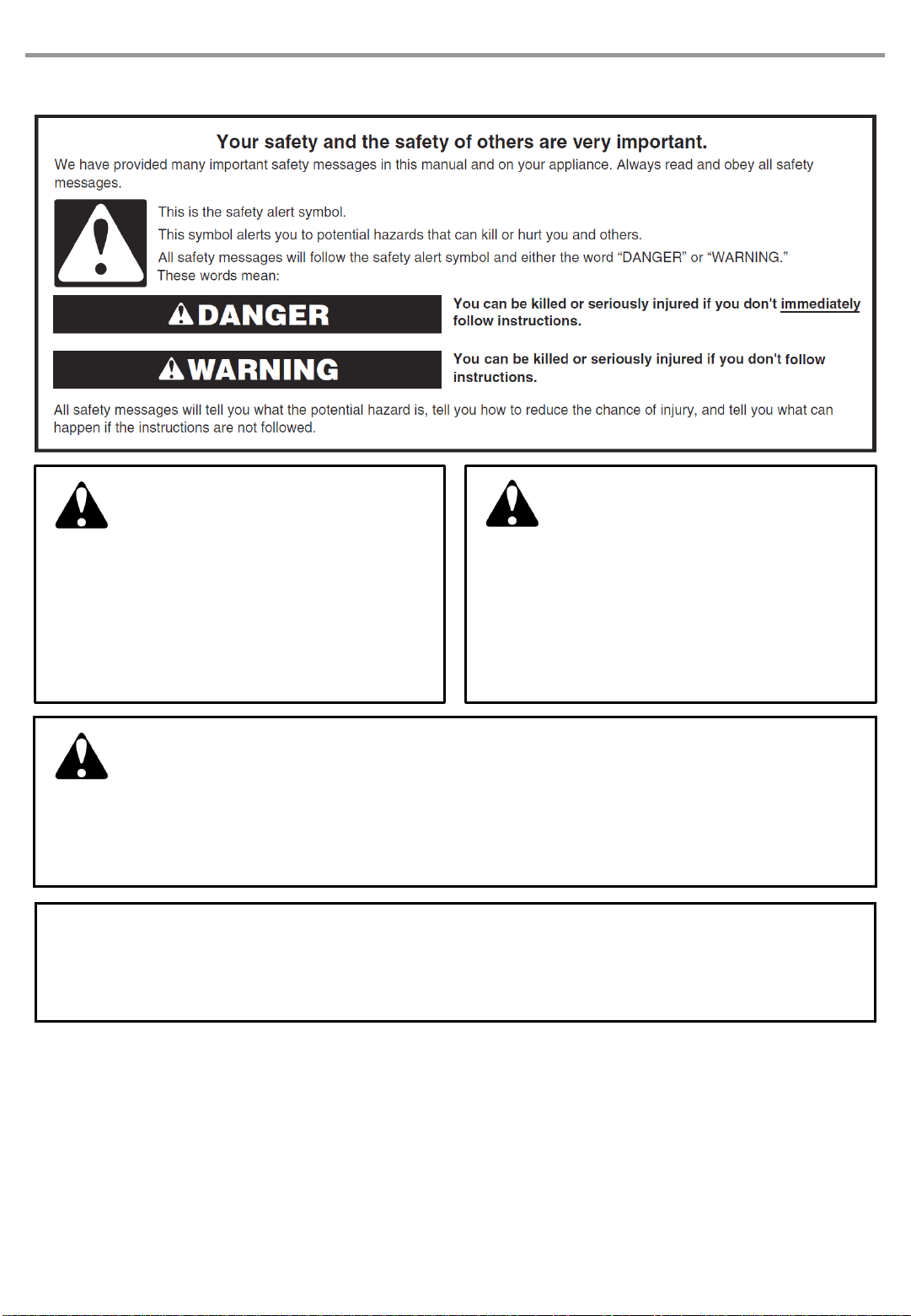
OUTDOOR BUILT-IN SIDE BURNER SAFETY
DANGER
If you smell gas:
1. Shut off gas to the appliance.
2. Extinguish any open flame.
3. Open lid.
4. If odor continues, keep away from the
appliance and immediately call your gas
supplier or your fire department.
WARNING
1. Do not store or use gasoline or other
flammable liquids or vapors in the
vicinity of this or any other appliance.
2. An LP cylinder not connected for use
shall not be stored in the vicinity of this
or any other appliance.
3
In the State of Massachusetts, the following installation instructions apply:
◼Installations and repairs must be performed by a qualified or licensed contractor, plumber, or gasfitter qualified or licensed by
the State of Massachusetts.
◼If using a ball valve, it shall be a T-handle type.
◼A flexible gas connector, when used, must not exceed 3 feet.
CALIFORNIA RESIDENTS ONLY - WARNING:
This product and the fuels used to operate this product (liquid propane), and the products of
combustion of such fuels, can expose you to chemicals including benzene, which is known
to the State of California to cause cancer and reproductive harm.
For more information go to: www.P65Warnings.ca.gov.

WARNING: To reduce the risk of fire, electrical shock,
Injury to persons, or damage when using the outdoor cooking
gas appliance, follow basic precautions, including the following:
◼Do not install portable or built-in outdoor cooking gas
appliances in or on a recreational vehicle, portable trailer,
boat or in any other moving installation.
◼Always maintain minimum clearances from combustible
construction, see “Location Requirements” section.
◼The outdoor cooking gas appliance shall not be located
under overhead unprotected combustible construction.
◼This outdoor cooking gas appliance shall be used only
outdoors and shall not be used in a building, garage, or
any other enclosed area.
◼Keep any electrical supply cord and fuel supply hose away
from any heated surfaces.
◼Keep outdoor cooking gas appliance area clear and free
from combustible material, gasoline and other flammable
vapors and liquids.
◼Do not obstruct the flow of combustion and ventilation air.
Keep the ventilation openings of the cylinder enclosure
free and clear from debris.
◼Inspect the gas cylinder supply hose before each use of
the outdoor cooking gas appliance. If the hose shows
excessive abrasion or wear, or is cut, it MUST be replaced
before using the outdoor cooking gas appliance. Contact
your dealer and use only replacement hoses specified for
use with the outdoor cooking gas appliance.
◼Visually check the burner flames.
They should be blue. Slight
yellow tipping is normal for
LP gas. The flames should
be approximately 1" (2.5 cm) high.
◼Check and clean burner/venturi tube for insects and insect
nest. A clogged tube can lead to fire under the outdoor
cooking gas appliance.
IMPORTANT SAFETY INSTRUCTIONS
◼The LP gas supply cylinder to be used must be:
- constructed and marked in accordance with the
Specification for LP Gas cylinders of the U.S.
Department of Transportation (DOT) or the National
Standard of Canada, CAN/CSA-B339, Cylinders,
Spheres, and Tubes for Transportation of Dangerous
Goods; and Commission.
- provided with a listed overfilling prevention device.
- provided with a cylinder connection device compatible
with the connection for outdoor cooking gas appliances.
◼Always check connections for leaks each time you connect
and disconnect the LP gas supply cylinder. See
“Installation Instructions” section.
◼When the outdoor cooking gas appliance is not in use, the
gas must be turned off at the supply cylinder.
◼Storage of an outdoor cooking gas appliance indoors is
permissible only if the cylinder is disconnected and
removed from the outdoor cooking gas appliance.
◼Cylinders must be stored outdoors and out of the reach of
children and must not be stored in a building, garage, or
any other enclosed area.
◼The pressure regulator and hose assembly supplied with
the outdoor cooking gas appliance must be used. A
replacement pressure regulator and hose assembly
specific to your model is available from your outdoor
cooking gas appliance dealer.
◼Gas cylinder must include a collar to protect the cylinder
valve.
◼For appliances designed to use a CGA791 connection:
Place a dust cap on cylinder valve outlet whenever the
cylinder is not in use. Only install the type of dust cap on
the cylinder va`lve outlet that is provided with the cylinder
valve. Other types of caps or plugs may result in leakage
of propane.
If the following information is not followed exactly, a fire causing
death or serious injury may occur.
◼Do not store a spare LP gas cylinder under or near this
outdoor cooking gas appliance.
◼Never fill the cylinder beyond 80 percent full.
SAVE THESE INSTRUCTIONS
4

◼
Natural gas regulator (marked “Natural Gas Regulator”)
◼10 ft (3.0 m) PVC flexible gas supplyhose with quick
connector
◼5.9 in. NG regulator hose
◼6 mm wrench
◼6 mm nut driver
◼Hex key
◼
Tape Measure
◼
Small, flat-blade screwdriver
◼
Flat-blade screwdriver
◼
#2 and #3 Phillips screwdriver
◼
Level
◼
Wrench or pliers
◼
Pipe wrench
◼
Scissors or cuttingpliers (to remove tiedowns)
◼
Noncorrosive leak-detection solution
INSTALLATION REQUIREMENTS
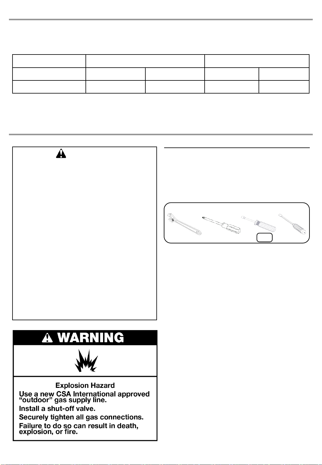
Tools and Parts
Gather the required tools and parts before starting installation. Read and follow the instructions provided with any tools listed here.
Configuration: Stand-Alone Side Burner (760-0023B)
Tools needed
Parts Supplied for 20 lb LP Gas Installation
◼Gas pressure regulator/hose assembly set for 11 in WC LP gas
◼LP gas fuel tank tray
Parts Supplied for Conversion to Natural Gas
◼1.70 mm Natural gas orifice for side burner (Model 770-0023B)
Parts Needed for Conversion to Natural Gas
◼Natural gas conversion kit (Order Part Number 710-0003A). Natural gas conversion kit includes:
◼Gas line shut off valve
◼½" male pipe thread nipple for connection to pressure regulator
◼LP gas-resistant pipe-joint compound
◼CSA design-certified outdoor flexible stainlesssteel appliance connector (4-5 ft [1.2-1.5 m]) or rigid gas supply line as needed
5

Location Requirements
Select a location that provides minimum exposure to wind and
traffic paths. The location should be away from strong draft
areas.
Do not obstruct flow of combustion and ventilation air.
Clearance to combustible construction for burner:
◼A minimum of 36” (92 cm) must be maintained between
the front, sides and back of the burner and any
combustible construction.
◼A 36” (92 cm) minimum clearance must also be maintained
below the cooking surface, and the burner shall not be
used under overhead combustible construction.
Product Dimensions
Built-In Outdoor
Side Burner Enclosure
The enclosure opening for the built-in outdoor side searing
burner is to be a minimum of 11.5" (29.2 cm) wide x 16.75"
(42.7 cm) long x 7.3" (18.4 cm) deep.
This built-in outdoor side burner is only for installation in a built-
in enclosure constructed only of non-combustible materials.
Non-combustiblematerials could be brick, firewall or steel. Do
not use wood or other combustiblematerials for built-in
enclosure.
6

Cabinet Cutout Dimensions
The illustration below includes cutout dimensions and minimum spacing requirements. The illustration is for reference. The design
of your cabinet layout can be personalized, but the dimensions for the cutouts and minimum spacing must be followed.
Counter or support surfaces must be level.
The installation of this side burner must conform with local codes or, in the absence of local codes, with either the National Fuel
Gas Code, ANSI Z223.1/NPFA 54, Natural Gas and Propane Installation Code, CSA B149.1, or Propane Storage and Handling
Code, B149.2.
NOTE: The outdoor side buner drops into the enclosure opening and is supported by its side flanges. Do not use a bottom support.
◼The island must be vented in one of the 2 following ways:
A 90°or a 180°ventilation in the island to ensure that air
flows through the island at either 90°or 180°.
◼Any enclosure for built-in installationis to have at least
one ventilationopening on an exposed exterior side
located within 2½" (6.0 cm) of the top and is to be a
minimum of 20 in.2 (129.0 cm2). One ventilation opening
within 1½" (3.0 cm) of the bottom of the enclosure,and the
bottom openingis to be a minimum of 10 in.2(64.5 cm2).
All vent openings are to be unobstructed. Every opening is
to be a minimum of 1/8" (0.32 cm) wide.
Any enclosure is to be ventilatedby openings at both the top
and lower levels of the enclosure. The following information is
the minimum for proper ventilation of your island construction.
◼There should be a minimum of 1 7/8" (4.4 cm) of clearance
from the bottom of the main burner bowl assembly island
for proper ventilation.
NOTE: There should be no solid surface underneath the
firebox portion of the side burner.
◼A minimum of 3" (7.6 cm) is required between the back of
the side burner and any noncombustiblematerials. A
minimum of 36" (92 cm) is required between the back of
the side burner and any combustible material.
Built-in Outdoor Side Burner Enclosure Ventilation for LP Gas
7

◼To ensure that the side burner operates properly, it is
recommendedthat the island have ventilationon all 4
sides as shown in the following illustration. The ventilation
holes should be as diagrammed to ensure adequate
ventilation for your side burner and island.
◼Proper ventilation is a required based on the above
mentioned specifications for your side burner to operate
properly.
Observe all governing codes and ordinances.
IMPORTANT: This installationmust conform with all local
codes and ordinances.In the absenceof local codes,
installationmust conform with American National Standard,
National Fuel Gas Code ANSI Z223.1 - latest edition or
CAN/CGA B149.1 –latest edition.
IMPORTANT: The side burner must be connectedto a
regulated gas supply.
Refer to the model/serial rating plate for information on the type
of gas that can be used. If this informationdoes not agree with
the type of gas available, check with your local gas supplier.
Gas Conversion:
No attempt shall be made to convert the side burner from the
gas specified on the model/serial rating plate for use with a
different gas type without consulting the serving gas supplier.
The conversion kit supplied with side burner must be used. See
“Gas Conversions” section for instructions.
Gas Pressure Regulator
A gas pressure regulator with the following pressure settings
must be used with the side burner. The inlet (supply) pressure
to the regulator shouldbe as follows for proper operation:
LP Gas:
Operating pressure:11 in WC
Inlet (supply) pressure: 11 to 14 in WC
Natural Gas:
Operating pressure:4 in WC
Inlet (supply) pressure: 7 to 14 in WC maximum.
Contact local gas supplier if you are not sure about the inlet
(supply) pressure.
Gas Supply Requirements
8

Gas Supply Line Pressure Testing
Testing above 1/2 psi (3.5 kPa) or 14 in WC (gauge):
The side burner and its individual shutoff valve must be
disconnected from the gas supply piping system during any
pressure testing of that system at test pressures greater than
1/2 psi (3.5 kPa).
Testing below 1/2 psi (3.5 kPa) or 14 in WC (gauge) or
lower:
The side burner must be isolated from the gas supply piping
system by closing its individual manual shutoff valve during any
pressure testing of the gas supply piping system at test
pressures equal to or less than 1/2 psi (3.5 kPa).
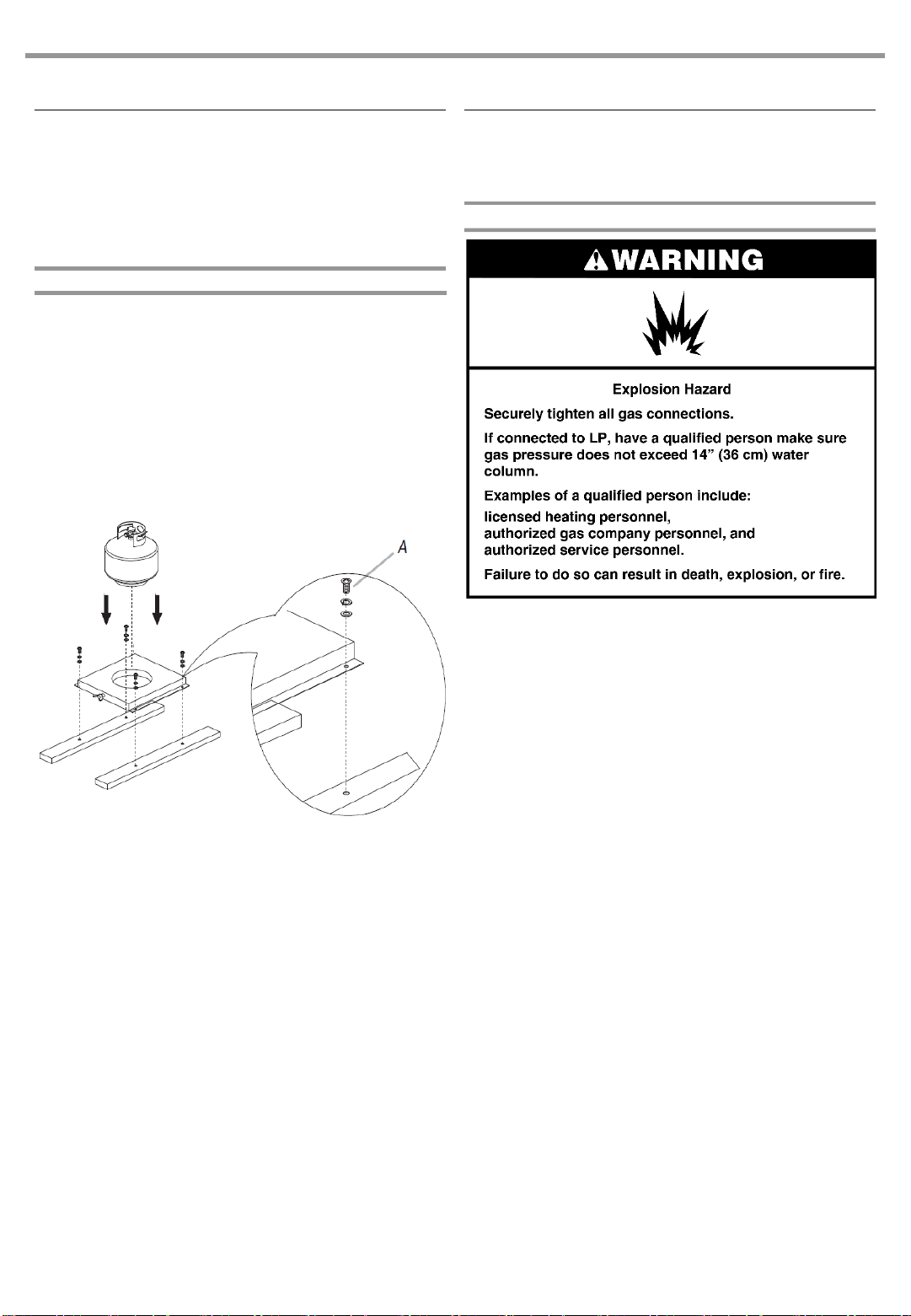
Gas Connection Requirements
This side burner is equipped for use with a 20 lb propane tank
(fuel tank not supplied). A gas pressure regulator/hose
assembly is supplied.
A. Gas pressure regulator/hose assembly
20 lb Propane Tank
The 20 lb LP gas fuel tank must be mounted and secured.
1. Open cabinet doors (if applicable).
2. Loosen the tank tray locking screw.
3. Place the 20 lb propane tank bottom collar into the
mounting hole in the tank tray.
4. Tighten the locking screw against the bottom collar of the
20 lb propane tank to secure.
5. Close cabinet doors (if applicable).
Make sure the tank is firmly securedin an upright position.
LP Gas Conversion Using a Local LP Gas Supply
If you want to convert to local LP gas supply, contact your local
gas company for specific instructions.
Natural Gas Conversion
Conversion must be made by a qualified gas technician.The
qualified Natural gas technician shall provide the Natural gas
supply to the selected side burner location in accordance with
the National Fuel Gas Code ANSI Z223.1/NFPA 54 - latest
edition, and local codes. For conversion to Natural gas, the
Natural Gas Conversion Kit supplied with the side burner must
be used. See the “Gas Conversions” section.
IMPORTANT: The gas installation must conform with local
codes, or in the absence of local codes, with the National Fuel
Gas Code, ANSI Z223.1/NFPA 54 - latest edition.
The gas supply line shall be equipped with an approved shutoff
valve. This valve should be located in the same area as the
side burner and should be in a location that allows ease of
opening and closing. Do not block accessto the shutoff valve.
The valve is for turning on or shutting off gas to the side burner.
A. Gas supply line
B. Shutoff valve “open” position
C. To side burner
B
A. Locking screw
B. Tank tray
C. 20 lb propane tank tray
AC
It is also design-certified by CSA International for local LP gas
supply or for Natural gas with appropriate conversion.
9
Install 20 lb Propane Tank Tray
The tank tray should be secured to a fixed location that can be
easily accessed and will allow the gas pressure regulator/ hose
assembly to connect to the 20 lb propane tank without kinking
or putting strain on the gas pressure regulator/ hose assembly.
1. Place the tank tray in a location that can be secured using
4 screws (supplied) through the predrilled holes.
2. Use 4 screws to secure the tank tray. The typical location
for a 20 lb propane tank is within the enclosure where the
tank can be turned on and off easily.
NOTE: A bracket or shelf (not supplied) that is large enough to
keep a second 20 lb propane tank from being stored in the
storage area under the side burner is required to be mounted
inside the island.
◼Unpack side burner. Remove all packaging materials and
remove side burner from carton.
◼Place side burner into outdoor enclosure but leave enough
room in back to connect to gas supply.
NOTE: If side burner is to be convertedto Natural gas, follow
instructions in the “Gas Conversions” section.
20 lb Propane Tank
IMPORTANT: A 20 lb propane tank must be purchased
separately.
IMPORTANT: The 20 lb propane tank must be mounted and
secured.
IMPORTANT: The gas pressure regulator/hose assembly
supplied with the burner must be used. Replacement gas
pressure regulator/hose assembly specific to your model is
available from your outdoor grill dealer.
To Connect the 20 lb Propance Tank:
1. Check that the 20 lb LP propane tank is in the “OFF”
position. If not, turn the valve clockwise until it stops.
2. Check that the 20 lb LP propane tank valve has the proper
type-1 external male thread connections per ANSI Z21.81.
3. Check that the burner control knobs are in the “OFF”
position.
4. Remove any debris and inspect the valve connections,
port, and gas pressure regulator/hose assembly for
damage.
NOTE: Always keep the LP cylinder at 90°(upright) orientation
to provide vapor withdrawal.
INSTALLATION INSTRUCTIONS
Built-in Outdoor Side Burner
Installation
Make Gas Connection
10
A. Four5/32-32 x 3/8” truss head screws

To Disconnect the 20 lb PropaneTank:
1. Check that the burner control knobs are in the “OFF”
position and the side burner is cool.
2. Check that the 20 lb propane tank is in the “OFF” position.
If not, turn the valve clockwise until it stops.
3. Using your hand, turn the gas pressure regulator/hose
assembly counterclockwiseto disconnect to the 20 lb LP
gas fuel tank as shown.
Hand loosen only. Use of a wrench could damage the
quick coupling nut.
4. Place dust cap on cylinder valve outlet whenever the
cylinder is not in use. Only install the type of dust cap on
the valve outlet that is provided with the cylinder valve.
Other types of caps or plugs may result in leakage of
propane.
A. Gas pressure regulator/hose assembly
B. 20 lb propane tank
5. Using your hand, turn the gas pressure regulator/hose
assembly clockwise to connect to the 20 lb propane tank
as shown.
Hand tighten only. Use of a wrench could damage the
quick coupling nut.
A. Gas pressure regulator/hose assembly
B. 20 lb propane tank
A
B
A. Gas pressure regulator/hose assembly
B. 20 lb propane tank
Make sure that the cylinder valve connectiondevice
properly mates with the connectiondevice attached to the
inlet of the pressure regulator.
6. Open the tank valve fully by turningthe valve
counterclockwise. Wait a few minutes for gas to move
through the gas line.
7. Before lighting the side burner, test all connections by
brushing on an approvednoncorrosive leak-detection
solution. Bubbles will show a leak.
8. If a leak is found, turn the tank valve off and do not use the
side burner. Contact a qualified gas technician to make
repairs.
11
GAS CONVERSIONS
6mm
Tools and Parts for Gas Conversion
Gather the required tools and parts before starting installation.
Read and follow the instructions provided with any tools listed
here.
Tools needed
Parts supplied
◼Natural gas orifices
Parts needed
◼Natural gas conversion kit Part Number 710-0003A. See
“Assistance” section to order. The conversion kit includes:
(NOT INCLUDED WITH APPLIANCE)
◼Natural gas regulator 4" W.C. (marked “Natural Gas
Regulator”)
◼10 ft (3.0 m) Natural gas hose with quick connector
◼5.9" (150 mm) Natural gas regulator hose
◼6 mm nut driver
◼6 mm wrench
◼Hex key
IMPORTANT: Gas conversions must be done by a qualified
installer. Before proceeding with conversion, shut off the gas
supply to the side burner.
12
Liquid Propane (LP) Natural Gas (NG)
Components Orifice Size BTU/HR Orifice Size BTU/HR
Side Burner 1.02 mm 12,000 1.70 mm 12,000
760-0023B (LP), 770-0023B (NG) orifice sizes
IMPORTANT: The burner valves in this grill have a specific BTU rating. This means that the amount of gas coming from
each orifice is controlled to create the BTU. The holes in the orifices themselves are drilled to different sizes so as to allow
the proper amount of gas to flow through them. Please note the chart above as an easy reference for the various orifice
opening sizes for the valves in the grill.
WARNING
This conversion kit shall be installed
by a qualified service agency in
accordance with the manufacturer’s
instructions and all applicable codes
and requirements of the authority
having jurisdiction. If the information in
these instructions is not followed
exactly, a fire, explosion or production
of carbon monoxide may result
causing property damage, personal
injury or loss of life. The qualified
service agency is responsible for the
proper installation of this kit. The
installation is not proper and complete
until the operation of the converted
appliance is checked as specified in
the manufacturer’s instructions
supplied with the kit.

8. Remove igniter junction wire from electronic igniter module.
9. Remove 3 screws off the front baffle.
10. Lift up front baffle away from burner.
11. Use a 6 mm socket and wrench or 6 mm nut driver to
remove the LP gas orifice from the end of gas valve.
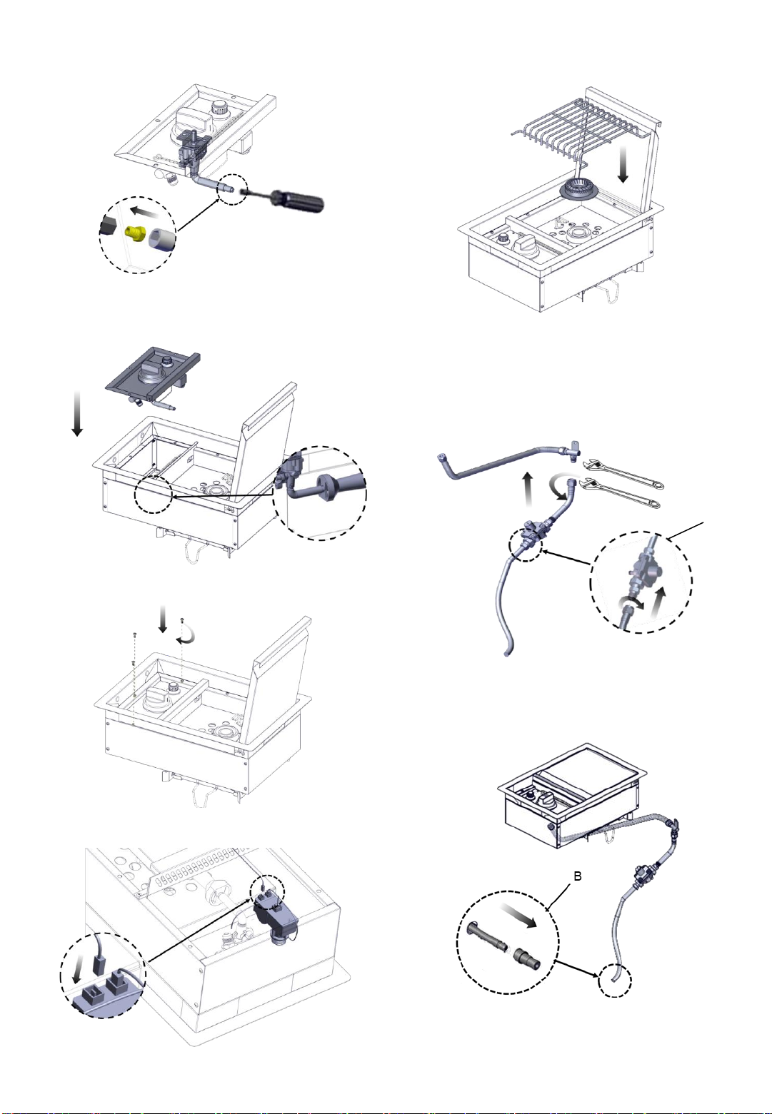
Conversion from LP Gas to
Natural Gas
Orifice Change and the Installation of the NG regulator
1. Before making any connections, check to ensure the
natural gas inlet pressure falls between the allowable
range of 7 in W.C. / 0.25 psi and 14 in W.C. / 0.5 psi. If the
NG inlet pressure does not fall within this range, contact
your local gas supplier.
2. Turn off the main gas supply valve.
3. Disconnect 20 lb propane tank (if present).
4. Turn off burner control valve.
5. Use screwdriver to remove screw holding the corrugated
pipe connector to the enclosure.
6. Use adjustablewrench to remove hose and regulator from
corrugated pipe connector.
7. Remove side burner cooking grid and burner cover.
13
12. Use a 6 mm socket and wrench or 6 mm nut driver to
install NG gas orifice to the end of gas valve.
13. Reinstall front baffle to burner.
IMPORTANT: Check that the orifice is properly installed
inside of the side burner gas valve.
14. Install the 3 screws.
15. Insert igniter junction wire from electronic igniter module.
14
16. Replace side burner cooking grid and burner cover.
17. Use an adjustable wrench to install Natural gas pressure
regulator and corrugated pipe to the corrugated pipe
connector.
18. Connect the brass connector on one end of the 10 ft (3.0
m) PVC flexible gas supplyhose to the Natural gas
pressure regulator (A).
19. Connect the quick connector on the other end of the 10 ft
(3.0 m) PVC flexible gas supplyhose to the rigid Natural
gas supply pipe (B).
A

15
Record Conversion
The LP appliance nameplate is located inside the grill cabinet
on the left-hand side.Once converted,place the NG appliance
nameplate as close as possible to the current LP appliance
nameplate without covering it.
In the last page of the Use and Care Guide, write “Converted to
Natural Gas”. Also record the conversion date and the
technician/company that performed the conversion.
20. Use screwdriver to install screw to hold the corrugate
connector to the enclosure.
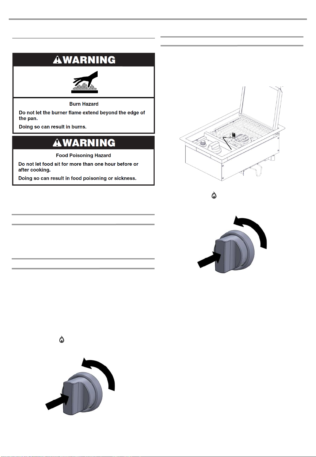
Manually Lighting the Side Burner
1. Open the lid completely.
2. Remove the manual lighting extension and attach a match
to the split ring.
3. Strike the match to light it.
4. Guide the lit match to the burner to light
5. Do not lean over the side burner. Push in and turn the
burner knob to “ ” for the burner closest to the lit match.
The burner will light immediately. When burner is lit, turn
knob to desired setting.
6. Remove match and replace manual lighting extension on
the right side panel.
IMPORTANT:
If burner does not light immediately, turn the burner knob to “○”
and wait 5 minutes beforerelighting.
If any burners do not light after attempting to light them
manually, contact the Customer Service Center. See the
“Assistance” section.
1. Open the lid completely.
2. Make sure control knob is turned to “○”.
3. Turn the gas supply on.
Natural gas or LP gas from a local supply
◼Using gas supply source other than 20 lb LP gas fuel tank:
Turn the shutoff valve to open position from the front of
gas supply line. The valve is open when the handle is
parallel to the gas pipe.
20 lb LP gas fuel tank
See the “Gas Supply Requirements” section.
◼Using a 20 lb LP gas fuel tank:
Slowly open the tank valve.
NOTE: If flow limiting device activates,your grill may not
light. If your grill does light, the flames will be low and will
not heat properly. Turn tank valve and all control knobs off
and wait 30 seconds. After shuttingoff the tank, very
slowly open tank valve and wait 5 seconds before lighting.
4. Do not lean over the side burner. Push in and turn the
burner knob to “ ” and hold in. The burner will light
immediately. Whenburner is lit, turn knob to desired
setting.
IMPORTANT:
If burner does not light immediately, turn the burner knob to “○”
and wait 5 minutes before relighting.
16
USING YOUR OUTDOOR SIDE BURNER
Lighting the Side Burner

General Cleaning
IMPORTANT: Before cleaning, make sure the control is off and
the side burner is cool. Always follow label instructions on
cleaning products.
For routine cleaning, wash with soap and water using a soft
cloth or sponge. Rinse with clean water and dry at once with a
soft, lint-free cloth to avoid spots and streaks.
Do not use steel wool to clean the side burner, as it will scratch
the surface.
To avoid weather damage to finish, use side burner cover.
STAINLESS STEEL
IMPORTANT: To avoid damage to stainless steel surfaces, do
not use soap-filled scouringpads, abrasive cleaners, cooktop
polishing creme, steel wool, gritty wash cloths or paper towels.
Cleaner should not contain chlorine. Damage may occur.
Food spills should be cleaned as soon as entire side burner is
cool. Spills may cause permanent discoloration.
Cleaning Method:
◼Rub in direction of grain to avoid scratching or damaging
the surface.
◼Stainless steel cleaner.
◼Liquid detergent or all-purpose cleaner.
◼Rinse with clean water and dry with soft, lint-free cloth.
◼Vinegar to remove hard water spots.
◼Glass cleaner to remove fingerprints.
EXTERIOR
The quality of this material resists most stains and pitting,
providing that the surface is kept clean, polished and covered.
Cleaning Method:
◼Apply stainless steel polishto all non-cooking areas before
first use. Reapply after each cleaning to avoid permanent
damage to surface.
◼Cleaning should always be followed by rinsing with clean
warm water.
◼Wipe the surface completely dry with a soft cloth.
◼For tough spots or baked-on grease, use a commercial
degreaser stainless steel.
INTERIOR
Discolorationof stainless steel on these parts is to be expected,
due to intense heat from the burners. Always rub in the
direction of the grain. Cleaning should always be followed by
rinsing with clean, warm water.
Cleaning Method:
◼Liquid detergent or all-purpose cleaner.
◼Rinse with clean water and dry completelywith a soft, lint-
free cloth.
◼A heavy-duty scrub sponge can be used with mild cleaning
products.
◼For small, difficult-to-clean areas, use a commercial
degreaser designed for stainless steel.
OUTDOOR SIDE BURNER CARE
SIDE BURNER CAP AND GRATE
Cleaning Method:
◼Clean with a brass bristle brush.
◼Wash grate using mild detergent, warm water and
degreaser.
◼Rinse with clean water and dry with soft, lint-free cloth.
◼Stainless steel cleaner.
GREASE CUP
IMPORTANT: The grease cup should only be removed when
grill is completely cool.
The grease cup collects grease and food particles that fall
through the burner. Clean often to avoid grease buildup.
Cleaning Method:
◼Remove the grease cup.
◼Wipe excess grease with mild detergent and warm water
using paper towels.
◼Rinse and dry thoroughly.
◼Replace grease box.
KNOBS AND FLANGE AREA AROUND KNOBS
IMPORTANT: To avoid damage to knobs or flange area
around knobs, do not use steel wool, abrasive cleaners, or
oven cleaner.
Do not soak knobs.
Cleaning Method:
◼Mild detergent, a soft cloth and warm water.
◼Rinse and dry.
CONTROL PANEL GRAPHICS
IMPORTANT: To avoid damage to control panel graphics, do
not use steel wool, abrasive cleaners or oven cleaner.
Do not spray cleaner directly onto panel.
Cleaning Method:
◼Clean around the burner labels gently; scrubbingmay
remove printing.
◼Mild detergent, soft cloth and warm water.
◼Rinse and dry.
17

Nothing will operate
▪Is the main or regulator gas shutoff valve in the off
position?
See the InstallationInstructions.
▪Is the side burner properly connected to the gas
supply?
Contact a trained repair specialist or see Installation
Instructions.
Low Heat
LP Gas:
For outdoor grills using a 20 lb propane tank, slowly open the
tank valve.
Note: If flow limiting device activates, your grill may not light. If
your grill does light, the flames will be low and will not heat
properly.
1. Turn tank valve and all control knobs off and wait 30
seconds.
2. After shutting off the tank, very slowly open the tank valve
and wait 5 seconds before lighting.
3. Light the burner. See “Lighting the Side Burner” section.
Natural Gas:
Gas pressure is affectedby size and length of the gas line from
the house to the grill. Contact a qualified gas technician to
provide the Natural gas supply to the selected grill locationin
accordancewith the National Fuel Gas Code ANSI
Z223.1/NFPA54 –latest edition and local codes.
TROUBLESHOOTING ASSISTANCE
Before calling for assistance, please check “Troubleshooting.” If
you still need help, follow the instructions below.
When calling, please know the purchase date and the complete
model and serial number of your appliance. This information
will help us to better respond to your request.
If you need replacement parts
If you have questions or need to order replacement parts,
contact Customer Service Center at 1-877-557-7473.
Please direct all correspondence to:
Nexgrill Industries, Inc.
14050 Laurelwood PI, Chino, CA 91710
Please include a daytime phone number in your
correspondence.
Accessories
Natural Gas Conversion Kit
Order Part Number 710-0003A
Spire 5-Burner Dual Energy Built-In Gas Grill
Order Part Number 740-0788P
Spire 6-Burner Dual Energy Built-In Gas Grill
Order Part Number 740-0781P
Built-In SB/SSB Component Hose Kit with High Capacity
Regulator
Order Part Number 711-0007
Built-In Grill Cabinet 20” High Double Drawer
Order Part Number 780-0016B
Built-In Grill Cabinet 15” Double Drawer
Order Part Number 780-0017A
Built-In Grill Cabinet Double Access Door
Order Part Number 780-0018B
Built-In Grill Cabinet Single Access Door
Order Part Number 780-0019A
18

Nexgrill warrants to the original consumer-purchaser only that this product (Model# 760/770-0023B) shall be free from defects in
workmanship and materials after correct assembly and under normal and reasonable home use for the periods indicated below
beginning on the date of purchase. The manufacturer reservesthe right to require photographic evidence of damage, or that
defective parts be returned, postage and or freight pre-paidby the consumer, for review and examination.
Burner –1 year LIMITED warranty against perforation.
Stainless steel parts: 3 Year LIMITED warranty against perforation, does not cover cosmetic issue like surface corrosion,
scratched and rust.
All other parts: 1 Year LIMITED warranty (Includes, but not limited to, valves, control panel, igniter, regulator, hoses); does not
cover chipping, scratching, cracking surface corrosion, scratches or rust.
Upon consumer supplying proof of purchase as provided herein, Manufacturer will repair or replace the parts which are proven
defective during the applicable warranty period. Parts required to complete such repair or replacementshall be free of charge to
you except for shippingcosts, as long as the purchaser is within the warranty period from the original date of purchase. The original
consumer-purchaser will be responsible for all shipping charges of parts replaced under the terms of this limited warranty. This
limited warranty is applicablein the United States and Canada only. It is only available to the original owner of the product and is
not transferable.Manufacturer requires reasonable proof of your date of purchase. Therefore,you should retain your sales receipt
and/or invoice.If the unit was received as a gift, please ask the gift-giver to send in the receipt on your behalf, to the below address.
Defective or missing parts subjectto this limited warranty will not be replaced without registrationor proof of purchase. This limited
warranty applies to the functionality of the product ONLY and does not cover cosmetic issues such as scratches, dents, corrosions
or discoloring by heat, abrasive and chemical cleaners or any tools used in the assembly or installation of the appliance, surface
rust, or the discoloration of stainless steel surfaces. Surface rust, corrosion, or powder paint chipping on metal parts that does not
affect the structural integrity of the product is not considereda defect in workmanship or material and is not covered by this
warranty. This limited warranty will not reimburse you for the cost of any inconvenience, food, personal injury or property damage.
If an original replacement part is not available,a comparable replacement part will be sent. You will be responsible for all shipping
charges of parts replaced under the terms of this limited warranty.
ITEMS MANUFACTURER WILL NOT PAY FOR:
◼Service calls to your home.
◼Repairs when your product is used for other than normal, single-familyhousehold or residential use.
◼Damage resulting from accident, alteration,misuse, lack of maintenance/cleaning, abuse, fire, flood, acts of God, improper
installation, and installationnot in accordancewith electrical or plumbing codes or use of products not approved by the
manufacturer.
◼Any food loss due to product failures.
◼Replacement parts or repair labor costs for units operated outside the United States or Canada.
◼Pickup and delivery of your product.
◼Postage fees or photo processing fees for photos sent in as documentation.
◼Repairs to parts or systems resulting from unauthorized modifications made to the product.
◼The removal and/or reinstallation of your product.
◼Shipping cost, standard or expedited, for warranty/non warranty and replacement parts.
DISCLAIMER OF IMPLIED WARRANTIES; LIMITATION OF REMEDIES
Repair or replacement of defective parts is your exclusiveremedy under the terms of this limited warranty. Manufacturer will not be
responsiblefor any consequential or incidental damages arising from the breach of either this limited warranty or any applicable
implied warranty, or for failure or damage resulting from acts of God, improper care and maintenance, grease fire, accident,
alteration, replacement of parts by anyone other than Manufacturer, misuse, transportation, commercial use, abuse, hostile
environments(inclement weather, acts of nature, animal tampering), improper installation or installation not in accordance with local
codes or printed manufacturer instructions.
LIMITED WARRANTY (Model # 760/770-0023B)
19

THIS LIMITED WARRANTY IS THE SOLE EXPRESS WARRANTY GIVEN BY THE MANUFACTURER. NO PRODUCT
PERFORMANCE SPECIFICATION OR DESCRIPTION WHEREVER APPEARING IS WARRANTED BY MANUFACTURER
EXCEPT TO THE EXTENT SET FORTH IN THlS LIMITED WARRANTY. ANY IMPLIED WARRANTY PROTECTION ARISING
UNDER THE LAWS OF ANY STATE, INCLUDING IMPLIED WARRANTY OF MERCHANTABILITY OR FITNESS FOR A
PARTICULAR PURPOSE OR USE, IS HEREBY LIMITED IN DURATION TO THE DURATION OF THIS LIMITED WARRANTY.
Neither dealers nor the retail establishment selling this product has any authority to make any additional warranties or to promise
remedies in addition to or inconsistent with those stated above. Manufacturer's maximum liability, in any event, shall not exceed the
documented purchase price of the product paid by the original consumer. This warranty only applies to units purchased from an
authorized retailer and or re-seller.
NOTE: Some states do not allow an exclusion or limitation of incidental or consequential damages, so some of the above
limitations or exclusions may not apply to you; this limited warranty gives you specific legal rights as set for herein. Rights may vary
depending on where your reside.
If you wish to obtain performance of any obligation under this limited warranty, you should write to:
Nexgrill Customer Relations
14050 Laurelwood PI
Chino, CA 91710
All consumer returns, parts orders, general questions, and troubleshooting assistance can be acquired by calling 1-877-557-7473.
20
This manual suits for next models
1
Table of contents
Languages:
Other Spire Grill manuals


Popular Grill manuals by other brands

Calflame
Calflame BBQ13P04 owner's manual

Members Mark
Members Mark Y0660LP-2 owner's manual

Silvercrest
Silvercrest STR 1000 A1 operating instructions

HIGH ONE
HIGH ONE HO-PL3525 Instructions for use

Outdoorchef
Outdoorchef DUALCHEF S 325 G Assembly instructions

Members Mark
Members Mark CG2320401-MM owner's manual


Silvercrest
Silvercrest SPM 2000 A16 operating instructions

Range Master
Range Master 463724313 Product guide

Silvercrest
Silvercrest 300874 operating instructions

Members Mark
Members Mark PRO Series Assembly instructions & user manual

Firesense
Firesense 62133 owner's manual

Proficook
Proficook PC-GG 1255 instruction manual