Spire 740-0788P Product information sheet
FOR OUTDOOR USE ONLY.
NOT FOR COMMERCIAL USE.
POUR USAGE EXTÉRIEUR SEULEMENT.
PAS À DES FINS COMMERCIALES.
IMPORTANT, RETAIN FOR FUTURE REFERENCE: READ CAREFULLY.
IMPORTANT, À CONSERVER POUR DE FUTURS BESOINS DE RÉFÉRENCE: À LIRE SOIGNEUSEMENT.
BUILT-IN OUTDOOR GRILL
Installation Instructions and Use & Care Guide
For questions about features, operation/performance, parts, accessories or service,
call: 1-833-55S-PIRE / 1-833-557-7473
Languages spoken: English, Spanish, French 8 a.m.-5 p.m., PST. Monday-Friday.
GRILL POUR L'EXTÉRIEUR UTILISATION
Instructions d’installation et Guide d’utilisation et d’entretien
Pour des questions à propos des caractéristiques, du fonctionnement/rendement, des pièces, des accessoires ou du service,
composer le: 1-833-55S-PIRE / 1-833-557-7473
Langues parlées: anglais , espagnol, français entre 8 h et 17 h, HNP, du lundi au vendredi.
740-0788P(LP) /750-0788P(NG)
19000996A1

2
TABLE OF CONTENTS
OUTDOOR GRILL SAFETY………………….……..…………3
INSTALLATION REQUIREMENTS……………………………..5
Tools and Parts………………………………………...……….…5
Location Requirements………………………………………...…5
Built-In Outdoor Grill Enclosure………………………………….6
Product Dimensions………………………………..……….…….6
Cabinet Cutout Dimensions………………………………………7
Gas Supply Requirements…………………..…..……………..…8
Gas Connection Requirements…………………..…..………..…9
Package Parts List ……..…………………..…..……………..…10
INSTALLATION INSTRUCTIONS……………..............…...12
Unpack Grill……………..…………………......………………...12
Install Grill………………..…………………......………………...12
Gas Connection ...…………………….............……………14
GAS CONVERSIONS……………….................................…...15
Tools and Parts for Gas Conversion ……....………………...15
Conversion from LP Gas to Natural Gas…....………………...16
Gas Connection ..…...……………….............……………18
Check and Adjust the Burners ………..………….………….…20
OUTDOOR GRILL USE ………………….………………..…21
Using Your Outdoor Grill ……………………….…………….…21
Using Your Rear Burner……………………………..……23
TIPS FOR OUTDOOR GRILLING ……………..……………...22
Cooking Methods ………………….…………………………….22
Grilling Chart ………………………….………………...…….….24
OUTDOOR GRILL CARE ………………………………...……25
Replacing the Igniter Battery …….…………………..……....25
General Cleaning ……………………………………….….....…25
TROUBLESHOOTING ...........................................................27
ASSISTANCE …………………………………………….…..…27
Accessories………………………………………………...……..27
WARRANTY ……………………………………….…………….28
REPLACEMENT PARTS………………………………...….…57
TABLE DES MATIÈRES
SÉCURITÉ DU GRIL D'EXTÉRIEUR….………..…….…….…30
EXIGENCES D’INSTALLATION…….……………..….....….32
Outils et pièces……….………….……..………........…..………32
Exigences d'emplacement…………….….………....….………32
Enceinte du gril d'extérieur encastré…………………….…….33
Dimensions du produit ……………………………………...…..33
Dimensions de l'ouverture àdécouper dans le placard……..34
Spécifications de l'alimentation en gaz………………..………35
Exigences concernant le raccordement au gaz………………37
Liste des pièces de l'emballage ………………..………………38
INSTRUCTIONS D’INSTALLATION……………....................40
Déballage du gril………………………………………………....40
Installation du gril…………………………………….…………..40
Raccordement au gaz………………………………….….….…42
CONVERSIONS POUR CHANGEMENT DE GAZ ……...…..43
Outils et pièces pour conversion de gaz ………….………....43
Conversion de propane àgaz naturel ……………….…...…...44
Raccordement au gaz …………………………............…....….46
Raccordement au gaz …………………………............…....….46
Contrôle et réglage des brûleurs ………………………….…...47
UTILISATION DU GRIL D’EXTÉRIEUR …….………..……...49
Utilisation de votre gril d'extérieur….….……….……..……….49
Utilisation du brûleur de tournebroche…………..……..……...51
CONSEILS POUR L'UTILISATION DU GRIL
D’EXTÉRIEUR………….…………..…...….……......…...……..52
Méthodes de cuisson….………………..……….…...……….…52
ENTRETIEN DU GRIL D’EXTÉRIEUR …………..…………...53
Remplacement de la pile de l’allumeur ……..…...………….53
Nettoage général ………………………………...……….…….53
DÉPANNAGE..........................................................................55
ASSISTANCE………………………………….…..………….…55
Accessoires………………………………………………...……..55
GARANTIE……………………………………..……..……...…..56
PIÈCES DE RECHANGE …………………..………………...58
DANGER
If you smell gas:
1. Shut off gas to the appliance.
2. Extinguish any open flame.
3. Open lid.
4. If odor continues, keep away from
the appliance and immediately call
your gas supplier or your fire
department.
WARNING
1. Do not store or use gasoline or
other flammable liquids or vapors in
the vicinity of this or any other
appliance.
2. An LP cylinder not connected for
use shall not be stored in the
vicinity of this or any other
appliance.

OUTDOOR GRILL SAFETY
3
IMPORTANT: This grill is manufactured for outdoor use only. See “Gas Supply Requirements” section. It is the responsibility of the
installer to comply with the minimum installation clearances specified on the model/serial rating plate. The model/serial rating plate
for freestanding models can be found on the left-hand cabinet door.
In the State of Massachusetts, the following installation instructions apply:
Installations and repairs must be performed by a qualified or licensed contractor, plumber, or gasfitter qualified or licensed by
the State of Massachusetts.
If using a ball valve, it shall be a T-handle type.
A flexible gas connector, when used, must not exceed 3 feet.
CALIFORNIA RESIDENTS ONLY -WARNING:
This product and the fuels used to operate this product (liquid propane), and the products of
combustion of such fuels, can expose you to chemicals including benzene, which is known
to the State of California to cause cancer and reproductive harm.
For more information, go to: www.P65Warnings.ca.gov.
WARNING
ELECTRICAL GROUNDING INSTRUCTIONS for Transformer -This appliance is equipped with a plug and should be
plugged directly into a properly grounded receptacle. When installed, must be electrically grounded in accordance with
local codes or in the absence of local codes, with the National Electrical Code, ANSI/NFPA 70 or the Canadian Electrical
Code, CSA C22.1 DO NOT cut or remove the grounding prong from this plug.
IMPORTANT SAFETY INSTRUCTIONS
WARNING: To reduce the risk of fire, electrical shock,
Injury to persons, or damage when using the outdoor cooking
gas appliance, follow basic precautions, including the following:
Do not install portable or built-in outdoor cooking gas
appliances in or on a recreational vehicle, portable trailer,
boat or in any other moving installation.
Always maintain minimum clearances from combustible
construction, see “Location Requirements” section.
The outdoor cooking gas appliance shall not be located
under overhead unprotected combustible construction.
This outdoor cooking gas appliance shall be used only
outdoors and shall not be used in a building, garage, or
any other enclosed area.
Keep any electrical supply cord and fuel supply hose away
from any heated surfaces.
Keep outdoor cooking gas appliance area clear and free
from combustible material, gasoline and other flammable
vapors and liquids.
Do not obstruct the flow of combustion and ventilation air.
Keep the ventilation openings of the cylinder enclosure
free and clear from debris.
Open the cabinet door and inspect the gas cylinder supply
hose before each use of the outdoor cooking gas
appliance. If the hose shows excessive abrasion or wear,
or is cut, it MUST be replaced before using the outdoor
cooking gas appliance. Contact your dealer and use only
replacement hoses specified for use with the outdoor
cooking gas appliance.
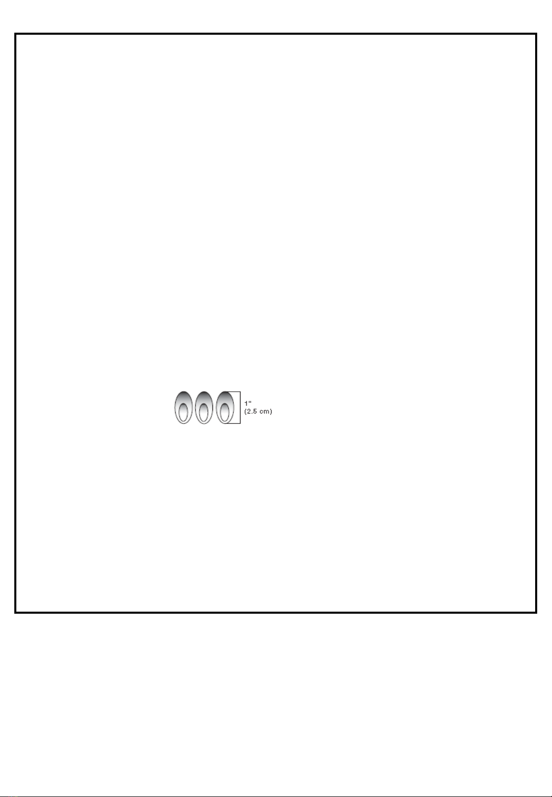
Visually check the burner flames.
They should be blue. Slight
yellow tipping is normal for
LP gas. The flames should
be approximately 1" (2.5 cm) high.
Check and clean burner/venturi tube for insects and insect
nest. A clogged tube can lead to fire under the outdoor
cooking gas appliance.
The LP gas supply cylinder to be used must be:
-constructed and marked in accordance with the
Specification for LP Gas cylinders of the U.S.
Department of Transportation (DOT) or the National
Standard of Canada, CAN/CSA-b339, Cylinders,
Spheres, and Tubes for Transportation of Dangerous
Goods and Commission.
-provided with a listed overfilling prevention device.
-provided with a cylinder connection device compatible
with the connection for outdoor cooking gas appliances.
Always check connections for leaks each time you connect
and disconnect the LP gas supply cylinder. See
“Installation Instructions” section.
When the outdoor cooking gas appliance is not in use, the
gas must be turned off at the supply cylinder.
Storage of an outdoor cooking gas appliance indoors is
permissible only if the cylinder is disconnected and
removed from the outdoor cooking gas appliance.
Cylinders must be stored outdoors and out of the reach of
children and must not be stored in a building, garage, or
any other enclosed area.
The pressure regulator and hose assembly supplied with
the outdoor cooking gas appliance must be used. A
replacement pressure regulator and hose assembly
specific to your model is available from your outdoor
cooking gas appliance dealer.
Gas cylinder must include a collar to protect the cylinder
valve.
For appliances designed to use a CGA791 connection:
Place a dust cap on cylinder valve outlet whenever the
cylinder is not in use. Only install the type of dust cap on
the cylinder va`lve outlet that is provided with the cylinder
valve. Other types of caps or plugs may result in leakage
of propane.
If the following information is not followed exactly, a fire causing
death or serious injury may occur.
Do not store a spare LP gas cylinder under or near this
outdoor cooking gas appliance.
Never fill the cylinder beyond 80 percent full.
SAVE THESE INSTRUCTIONS
4

INSTALLATION REQUIREMENTS
Location Requirements
Tools and Parts
Gather the required tools and parts before starting installation.
Read and follow the instructions provided with any tools listed
here.
Tools Needed
Tape Measure
Small, flat-blade screw
driver
#2 and #3 Phillips screw
driver
Level
Wrench or pliers
Pipe wrench
Scissors or cutting pliers
(to remove tiedowns)
Noncorrosive leak-
detection solution
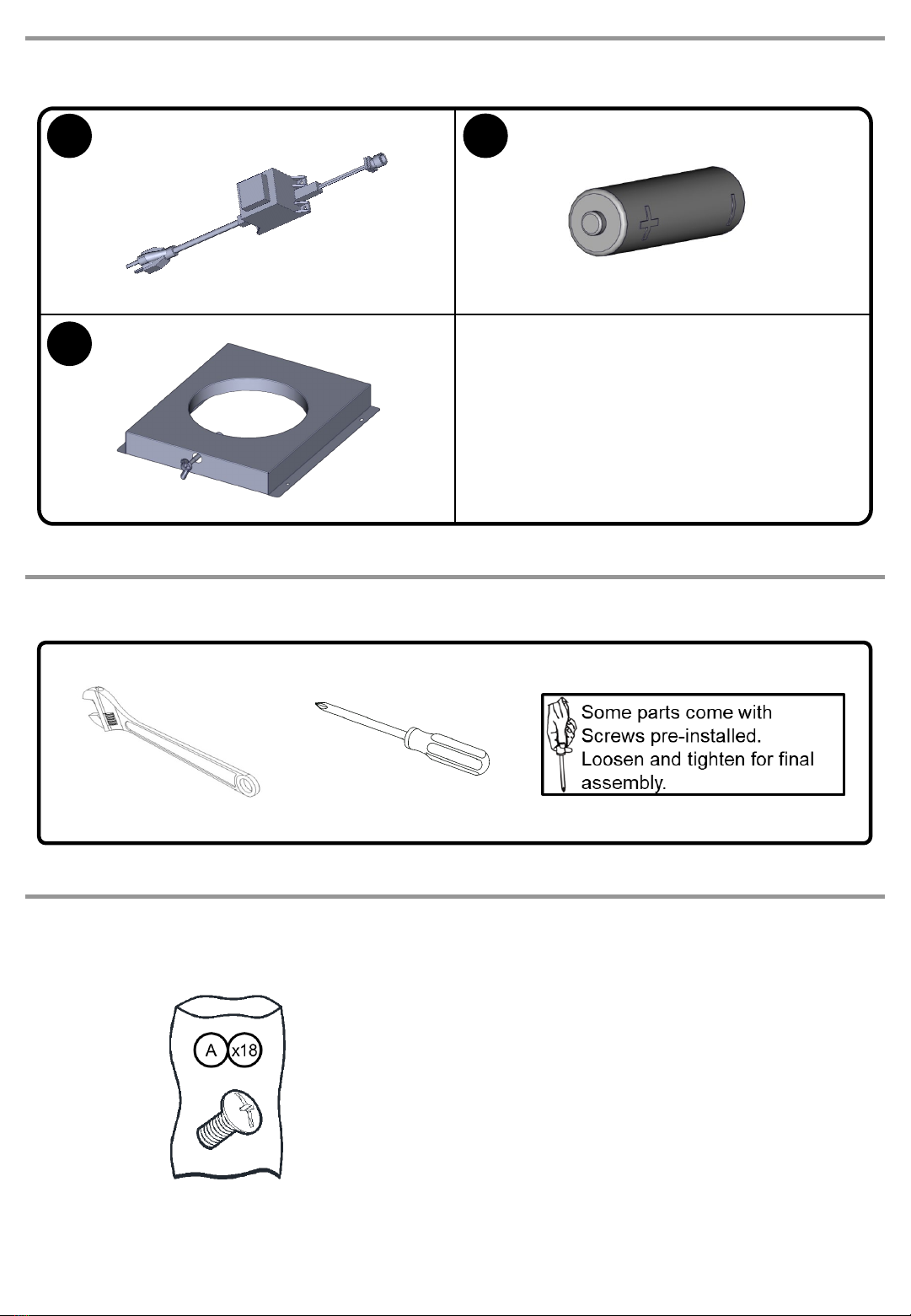
Parts Supplied
Gas pressure regulator/hose assembly set for 11” WCP LP
gas.
1 –“AA” size alkaline battery
20 lb LP gas fuel tank tray
12 screws (for installing 20 lb LP gas fuel tank tray, 90°
clamp/Natural gas regulator clamp)
Hardware packet
2 piece 90°clamp (for mounting 90°connector)
Hex wrench (for loosening control knobs)
Warming rack
Parts Needed
20 lb LP gas fuel tank
Parts Supplied for Conversion to Natural Gas
Natural gas conversion kit (which includes):
Natural gas regulator (marked “Natural Gas
Regulator”)
10 ft (3.0 m) PVC flexible gas supply hose with quick
connector
6 mm nut driver
Natural gas regulator clamp
2.05 mm Natural gas orifice for rotisserie/infrared
burner
2.10 mm Natural gas orifice for infrared searing
burner
Parts Needed for Conversion to Natural Gas
Gas line shut off valve
½" male pipe thread nipple for connection to pressure
regulator
LP gas-resistant pipe-joint compound
CSA design-certified outdoor flexible stainless steel
appliance connector (4-5 ft [1.2-1.5 m]) or rigid gas supply
line as needed
Select a location that provides minimum exposure to wind and
traffic paths. The location should be away from strong draft
areas.
Do not obstruct flow of combustion and ventilation air.
Clearance to combustible construction for outdoor grills:
A minimum of 36” (92.0 cm) must be maintained between
the front of the grill hood, sides and back of the grill and
any combustible construction.
A 36” (92.0 cm) minimum clearance must also be
maintained below the cooking surface, and the grill shall
not be used under overhead combustible construction.
Rotisserie (accessory is not included)*
If you equip your grill with a rotisserie, a 6” (15.2 cm) minimum
clearance is needed for the rotisserie motor.
A grounded, 3-prong outlet located to the left of the grill is
required.
*See “Assistance” section to order.
5

Product Dimensions
Built-In Outdoor Grill Enclosure
The enclosure for the built-in outdoor grill is to be a minimum of
11" (28.0 cm) high x 23" (58.4 cm) deep x 36" (91.4 cm) wide.
This built-in outdoor grill is only for installation in a built-in
enclosure constructed only of noncombustible materials. Non-
combustible materials could be brick, firewall or steel. Do not
use wood or other combustible materials for built-in enclosure.
6

Cabinet Cutout Dimensions
The illustration below includes cutout dimensions and minimum spacing requirements. The illustration is for reference. The design
of your cabinet layout can be personalized, but the dimensions for the cutouts and minimum spacing must be followed.
Center or support surfaces must be level.
The installation of this grill must conform with local codes or, in the absence of local codes, with either the National Fuel Gas Code,
ANSI Z223.1/NPFA 54, Natural Gas and Propane Installation Code, CSA B149.1, or Propane Storage and Handling Code, B149.2.
Copies of the standards listed may be obtained from:
CSA International
8501 East Pleasant Valley Rd.
Cleveland, Ohio 44131-5575
NOTE: The grill drops into the opening and is supported by its side flanges. Do not use a bottom support.
The island must be vented in one of the 2 following ways:
A 90°or a 180°ventilation in the island to ensure that air
flows through the island at either 90°or 180°.
Any enclosure for built-in installation is to have at least
one ventilation opening on an exposed exterior side
located within 2½" (6.0 cm) of the top and is to be a
minimum of 20 in.2 (129.0 cm2). One ventilation opening
within 1½" (3.0 cm) of the bottom of the enclosure, and the
bottom opening is to be a minimum of 10 in.2(64.5 cm2).
All vent openings a re to be unobstructed. Every opening
is to be a minimum of 1/8" (0.32 cm) wide.
Built-in Outdoor Grill Enclosure Ventilation for LP Gas
Any enclosure is to be ventilated by openings at both the top
and lower levels of the enclosure. The following information is
the minimum for proper ventilation of your island construction.
There should be a minimum of 1 7/8" (4.4 cm) of clearance
from the bottom of the main burner bowl assembly island
for proper ventilation.
NOTE: There should be no solid surface underneath the
firebox portion of the grill.
A minimum of 3" (7.6 cm) is required between the back of
the grill and any noncombustible materials. A minimum of
36" (92 cm) is required between the back of the grill and
any combustible material.
7
13.00”
(330mm)
22.00”
(559mm)

LP Gas
LP Gas Pressure Regulator/Hose Assembly Location
Measurements shown are for attaching the LP gas pressure
regulator/hose assembly to the enclosure.
Natural Gas Conversion
Natural Gas Pressure Regulator Location
Measurements shown are for attaching the Natural gas
pressure regulator to the enclosure.
To ensure that the grill operates properly, it is
recommended that the island have ventilation on all 4
sides as shown in the following illustration. The ventilation
holes should be as diagrammed to ensure adequate
ventilation for your grill and island.
Proper ventilation is a required based on the above
mentioned specifications for your grill to operate properly.
Natural Gas Conversion
Natural Gas Pressure Regulator Location
Measurements shown are for attaching the Natural gas
pressure regulator to the enclosure.
Observe all governing codes and ordinances.
IMPORTANT: This installation must conform with all local
codes and ordinances. In the absence of local codes,
installation must conform with American National Standard,
National Fuel Gas Code ANSI Z223.1 -latest edition or
CAN/CGA B149.1 – latest edition.
IMPORTANT: Grill must be connected to a regulated gas
supply. Refer to the model/serial rating plate for information on
the type of gas that can be used. If this information does not
agree with the type of gas available, check with your local gas
supplier.
Gas Supply Requirements
8
B
Gas Conversion:
No attempt shall be made to convert the grill from the gas
specified on the model/serial rating plate for use with a different
gas type without consulting the serving gas supplier. The
conversion kit supplied with grill must be used. See “Gas
Conversions” section for instructions.
Gas Pressure Regulator
The gas pressure regulator supplied with this grill must be used.
The inlet (supply) pressure to the regulator should be as follows
for proper operation:
LP Gas:
Operating pressure: 11" (27.9 cm) WCP
Inlet (supply) pressure: 11" to 14" (27.9 cm to 35.5 cm) WCP
Natural Gas:
Operating pressure: 4" (10.2 cm) WCP
Inlet (supply) pressure: 7" to 14" (17.8 cm to 35.5 cm) WCP
maximum.
Contact local gas supplier if you are not sure about the inlet
(supply) pressure.
Gas Supply Line Pressure Testing
Testing above 1/2 psi (3.5 kPa) or 14" (35.5 cm) WCP
(gauge):
The grill and its individual shutoff valve must be disconnected
from the gas supply piping system during any pressure testing
of that system at test pressures greater than 1/2 psi (3.5 kPa).
Testing below 1/2 psi (3.5 kPa) or 14" (35.5 cm) WCP
(gauge) or lower:
The grill must be isolated from the gas supply piping system by
closing its individual manual shutoff valve during any pressure
testing of the gas supply piping system at test pressures equal
to or less than 1/2 psi (3.5 kPa).
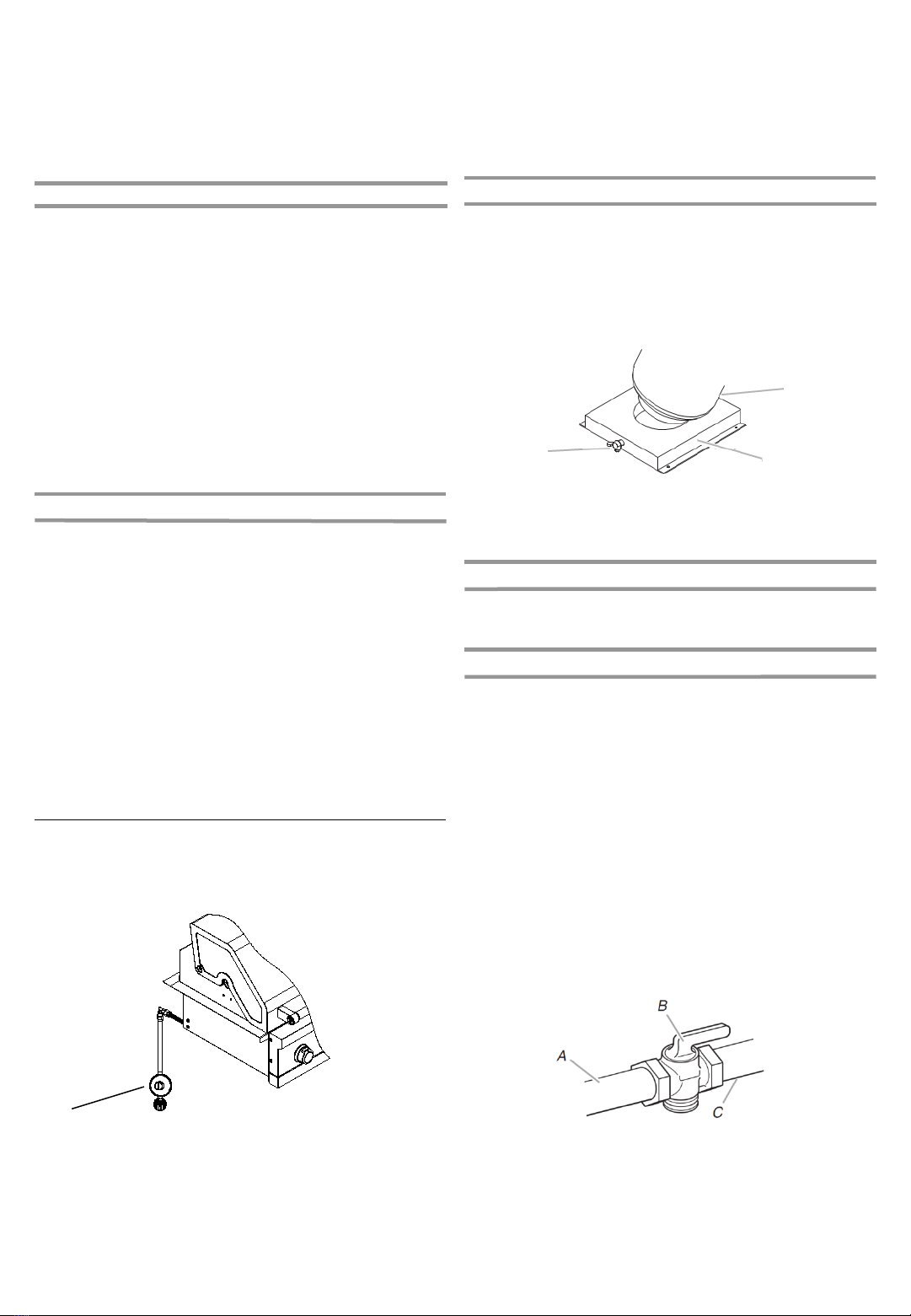
Gas Connection Requirements
This grill is equipped for use with a 20 lb LP gas fuel tank (fuel
tank not supplied). A gas pressure regulator/hose assembly is
supplied.
A. Gas pressure regulator/hose assembly
Any brand of 20 lb propane tank is acceptable for use with the
grill, provided that it is compatible with the grill’s retention
means (tank tray included).
It is also design-certified by CSA International for local LP gas
supply or for Natural gas with appropriate conversion.
20 lb Propane Tank
The 20 lb propane tank must be mounted and secured.
1. Open cabinet doors.
2. Loosen the tank tray locking screw.
3. Place the 20 lb propane tank bottom collar into the
mounting hole in the tank tray.
4. Tighten the locking screw against the bottom collar of the
20 lb LP gas fuel tank to secure.
A
A. Locking screw
B. Tank tray
C. 20 lb propane tray
LP Gas Conversion Using a Local LP Gas Supply
If you want to convert to local LP gas supply, contact your local
gas company for specific instructions.
Natural Gas Conversion
Conversion must be made by a qualified gas technician. The
qualified Natural gas technician shall provide the Natural gas
supply to the selected grill location in accordance with the
National Fuel Gas Code ANSI Z223.1/NFPA 54 -latest edition,
and local codes. For conversion to Natural gas, the Natural Gas
Conversion Kit supplied with the grill must be used. See the
“Gas Conversions” section.
IMPORTANT: The gas installation must conform with local
codes, or in the absence of local codes, with the National Fuel
Gas Code, ANSI Z223.1/NFPA 54 -latest edition.
The gas supply line shall be equipped with an approved shutoff
valve. This valve should be located in the same area as the grill
and should be in a location that allows ease of opening and
closing. Do not block access to the shutoff valve. The valve is
for turning on or shutting off gas to the grill.
A. Gas supply line
B. Shutoff valve “open” position
C. To grill
AC
9
5 6
78
910
1
3 4
2
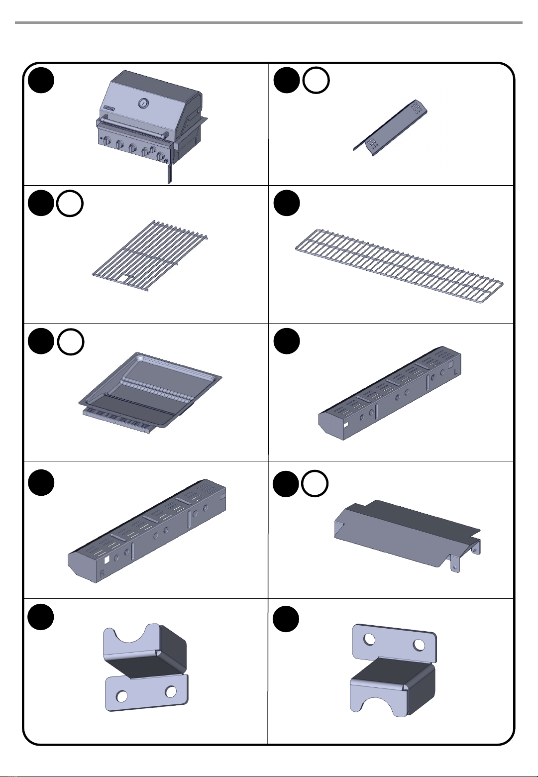
10
x2
x3
x5
PACKAGE PARTS LIST
x2
11
13
12
11
PACKAGE PARTS LIST
TOOLS NEEDED
HARDWARE PACKAGE LIST
W5/32”-32 x 2/5”
screw
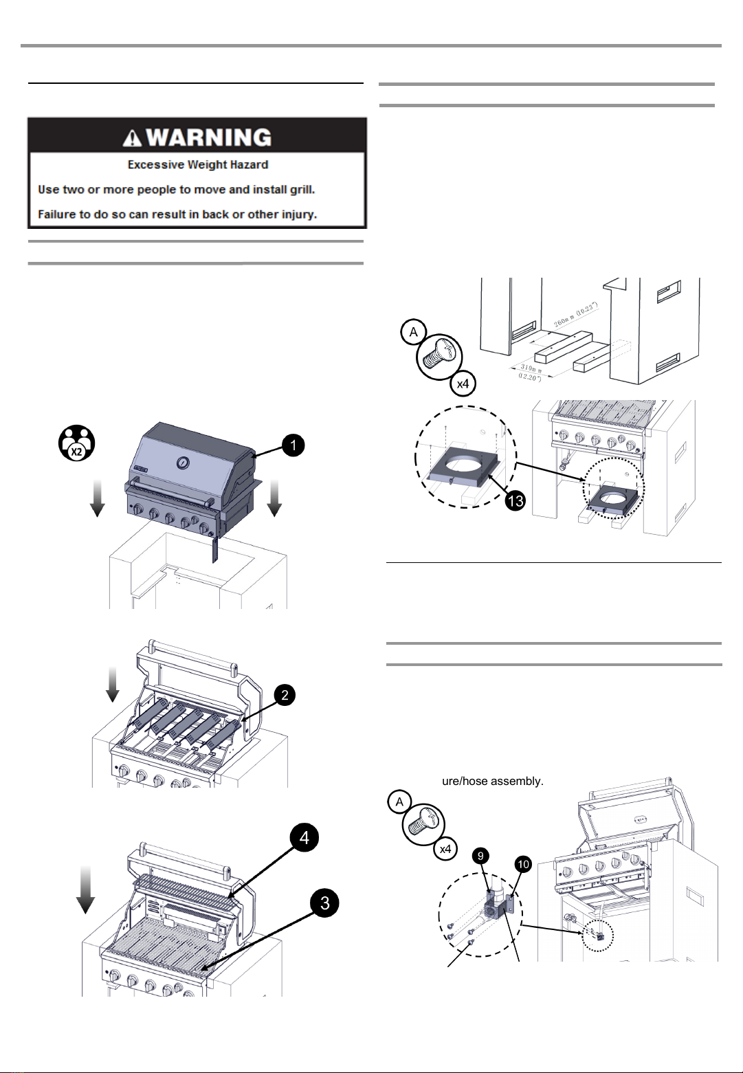
Unpack and Place the Grill:
1. Remove all packaging materials and remove grill from the
shipping base.
2. Move grill close to desired outdoor location.
3. Open the grill hood.
4. Using utility knife to cut yellow straps and packing tape to
open box from top and remove the boxes.
5. Remove the warming shelf and grill grates from inside the
grill and remove the package inside the firebox.
6. Remove foam block and wrap from inside the grill.
7. Place the grill on the support base.
8. Place the Flame Tamer to the grill.
9. Place Cooking Grid and Warming Shelf as shown.
Install 20 lb Propane Tank Tray
The tank tray should be secured to a fixed location that can be
easily accessed and will allow the gas pressure regulator/ hose
assembly to connect to the 20 lb propane tank without kinking
or putting strain on the gas pressure regulator/ hose assembly.
1. Place the tank tray in a location that can be secured using
4 screws (supplied) through the predrilled holes.
2. Use 4 screws to secure the tank tray. The typical location
for a 20 lb propane tank is within the enclosure where the
tank can be turned on and off easily.
INSTALLATION INSTRUCTIONS
Unpack Grill
A. Four 5/32" x 10 mm truss head screws
12
Install Grill
Place grill into outdoor enclosure but leave enough room in the
back to connect to the gas supply.
LP Gas Installation
1. Check that the LP gas pressure regulator/hose assembly
is positioned under the grill (as shown in the following
illustration) and is not pinched or kinked.
2. Use 4 screws and the 2-piece 90°clamp mounting
bracket provided to attach the 90°brass connector to the
back of the enclosure. The brass connector is located
between the flexible gas hose and the LP gas
pressure/hose assembly.
A. 4 screws
B. 2 piece 90
°
clamp mounting bracket
AB
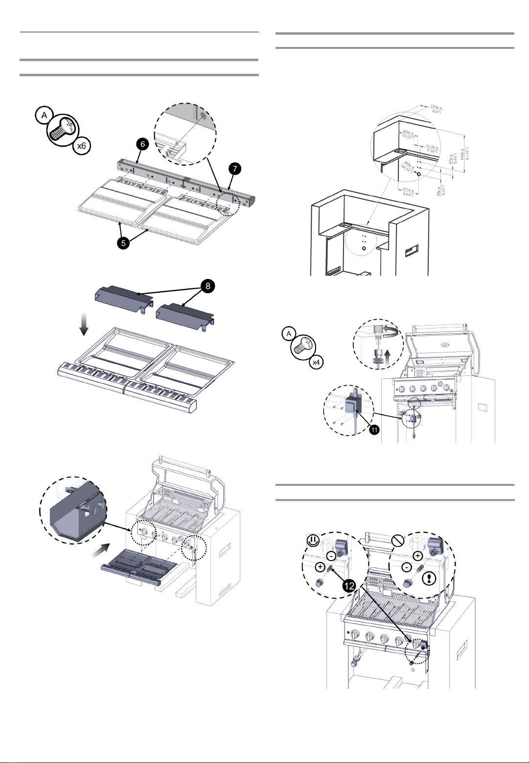
Install Grill
13
Battery Installation
1. Install the battery into the igniter as figure shown below.
Power Plug-in Installation
Connect the power adapter to provide the power for the light in
the grill.
Measurements shown are for attaching the Transformer to the
enclosure.
Plug in the power plug to electricity power wall jack.
Grease Tray Installation
1. Install the handle for the Grease Tray.
2. Place the Tray Cover to Grease Tray.
3. Insert Grease Tray into the grill as shown below.
1. Install the power adapter mounting bracket with 4 screws.
2. Connect the power adapter to the jack attached with the
grill. Tight up the connection by twist the knot.

4. Remove any debris and inspect the valve connections,
port, and gas pressure regulator/hose assembly for
damage.
NOTE: Always keep the tank at 90°(upright) orientation
to provide vapor withdrawal.
5. Using your hand, turn the gas pressure regulator/hose
assembly anticlockwise to connect to the 20 lb propane
tank as shown.
Hand tighten only. Use of a wrench could damage the
quick coupling nut.
6. Open the tank valve fully by turning the valve
counterclockwise. Wait a few minutes for gas to move
through the gas line.
7. Before lighting the grill, test all connections by brushing on
an approved noncorrosive leak-detection solution. Bubbles
will show a leak.
8. If a leak is found, turn the tank valve off and do not use the
grill. Contact a qualified gas technician to make repairs.
9. The igniter battery is not factory installed. A “AA” size
alkaline battery is in the accessory box on the grill grate.
Install battery following the instructions in “Replacing the
Igniter Battery” section.
10. Go to “Check and Adjust the Burners” section.
To Disconnect the 20 lb Propane Tank:
1. Check that the burner control knobs are in the “OFF”
position and the grill is cool.
2. Check that the 20 lb propane tank is in the “OFF” position.
If not, turn the valve clockwise until it stops.
3. Using your hand, turn the gas pressure regulator/hose
assembly clockwise to disconnect to the 20 lb propane
tank as shown.
Hand loosen only. Use of a wrench could damage the
quick coupling nut.
4. Place dust cap on cylinder valve outlet whenever the
cylinder is not in use. Only install the type of dust cap on
the valve outlet that is provided with the cylinder valve.
Other types of caps or plugs may result in leakage of
propane.
NOTE: If grill is to be converted to Natural gas, follow
instructions in the “Gas Conversions” section.
20 lb Propane Tank
IMPORTANT: : A 20 lb propane tank must be purchased
separately.
IMPORTANT: The gas pressure regulator/hose assembly
supplied with the grill must be used. Replacement gas pressure
regulator/hose assembly specific to your model is available
from your outdoor grill dealer.
To Install the 20 lb Propane Tank:
1. Install the 20 lb propane tank into the compartment below
the grill.
2. Tighten the locking screw against the bottom collar of the
20 lb propane tank to secure.
To Connect the 20 lb Propane Tank:
1. Check that the 20 lb propane tank is in the “Off” position. If
not, turn the valve clockwise until it stops.
2. Check that the 20 lb propane tank valve has the proper
type-1 external male thread connections per ANSI Z21.81.
3. Check that the burner control knobs are in the “Off”
position.
A. Gas pressure regulator/hose assembly
B. 20 lb propane tank
Gas Connection
14
GAS CONVERSIONS
15
Liquid Propane (LP) Natural Gas (NG)
Components Orifice Size BTU/HR Orifice Size BTU/HR
Main Burner 0.94 mm 10,000 1.54 mm 10,000
Rear Burner 1.07 mm 13,000 1.84 mm 13,000
740-0788P (LP), 750-0788P (NG) orifice sizes
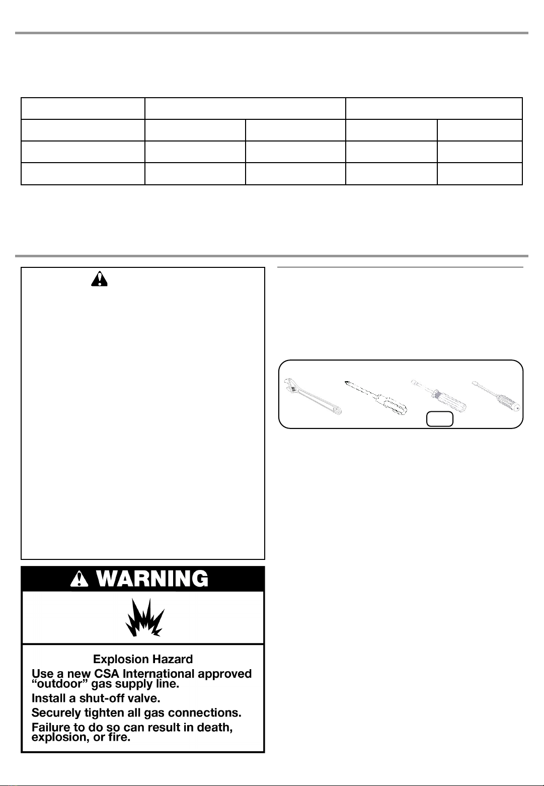
WARNING
This conversion kit shall be installed
by a qualified service agency in
accordance with the manufacturer’s
instructions and all applicable codes
and requirements of the authority
having jurisdiction. If the information in
these instructions is not followed
exactly, a fire, explosion or production
of carbon monoxide may result
causing property damage, personal
injury or loss of life. The qualified
service agency is responsible for the
proper installation of this kit. The
installation is not proper and complete
until the operation of the converted
appliance is checked as specified in
the manufacturer’s instructions
supplied with the kit.
IMPORTANT: The different burner valves in this grill have different BTU ratings. This means that the amount of gas coming from
each orifice varies in order to create the BTU's. The holes in the orifices themselves are drilled to different sizes to allow the proper
amount of gas to flow through them. Please note the chart above as an easy reference for the various orifice opening sizes for the
different valves in the grill.
Tools and Parts for Gas Conversion
Gather the required tools and parts before starting installation.
Read and follow the instructions provided with any tools listed
here.
Tools needed
Parts supplied
Natural gas orifices
Parts needed
Natural gas conversion kit Part Number 710-0003. See
“Assistance” section to order. The conversion kit includes:
(NOT INCLUDED WITH APPLIANCE)
Natural gas regulator 4" W.C. (marked “Natural Gas
Regulator”)
3.0 m / 10 ft Natural gas hose with quick connector
150 mm / 5.9 in Natural gas regulator hose
6 mm nut driver
6 mm wrench
Hex key
IMPORTANT: Gas conversions must be done by a qualified
installer. Before proceeding with conversion, shut off the gas
supply to the grill.
6mm

Conversion from LP Gas to Natural
Gas
Installation of the regulator
1. Turn off all burner control valves.
2. Turn off the main gas supply valve.
3. Disconnect 20 lb propane tank (if present) and remove the
tank from the grill cabinet.
4. Use a Phillips screwdriver to remove the 2-piece 90°
clamp mounting bracket from the cabinet wall.
5. Use an adjustable wrench to remove the LP gas pressure
regulator/hose assembly from the 90°brass adapter.
6. Install the Natural gas pressure regulator onto the flexible
gas hose from the grill.
16
Change Grill Main Burner Valve Orifices
1. Remove the grates and flame tamers.
2. Remove the 2 screws and cotter clip that hold the burner in
place. Set the screw and clip aside.
3. Remove the burner from the grill by lifting the burner out
7. Check that the Natural gas pressure regulator is
positioned under the grill (as shown in the following
illustration) and is not pinched or kinked.
Use 4 screws to attach the Natural gas pressure regulator
to the back of the enclosure

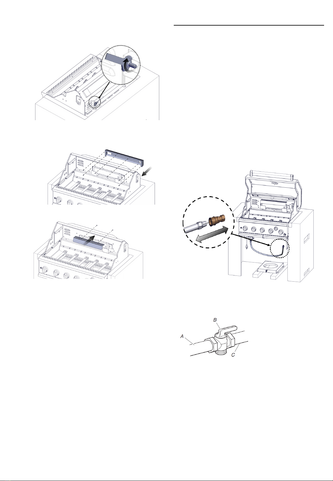
Change The Rear Burner Orifice
1. Use a screwdriver to remove the two screws from the rear
burner heat shield. Remove the heat shield.
2. Unscrew from the rear burner cover and remove the sear
burner rear cover.
3. Use an adjustable wrench to remove the brass elbow.
4. Use a 6 mm socket wrench or 6 mm nut driver to remove
the orifice. Replace with the corresponding natural gas
orifice.
IMPORTANT: Check that the NG orifice is properly
installed inside the valve.
17
4. Use a 6 mm socket and wrench or 6 mm nut driver to
remove the LP brass orifice from the end of gas valve. The
main burner NG orifice is located behind the LP orifice, so
no additional orifice needs to be installed.
5. Reinsert the burner and reattach using the cotter clip and
screws previously removed. Repeat the procedure for
each main burner.
6. Position the igniters so they are 3.2 mm / 1/8 in away from
each burner.
18
5. Reinstall the rear burner brass elbow by using a wrench.
6. Reinstall the rear burner rear cover, and heat shield.
5. Open the manual shutoff valve in the gas supply line. The
valve is open when the handle is parallel to the gas pipe.
6. Test all connections by brushing on an approved
noncorrosive leak detection solution. Bubbles will show a
leak. Correct any leak found.
7. The igniter battery is not factory installed. A “AA” size
alkaline battery is located in the accessory box on the grill
grate. Install battery at this time following the instructions
in “Replacing the Igniter Battery” section.
8. Go to “Check and Adjust the Burners” section.
A. Gas supply line
B. Shutoff valve “open” position
C.To grill
Gas Connection
1. Before making any connections, check to ensure the
natural gas inlet pressure falls between the allowable
range of 7" W.C. / 0.25 psi and 14" W.C. / 0.5 psi. If the
NG inlet pressure does not fall within this range, contact
your local gas supplier.
2. A combination of pipe fittings must be used to connect the
grill to the existing gas line.
The 10 ft (3.0 m) PVC flexible gas supply hose design
certified by CSA must be used.
Pipe-joint compounds suitable for use with Natural
gas must be used. Do not use Teflon®† tape.
There must be a certified manual shut-off valve in the
gas supply line near the grill for easy access.
3. Connect the brass connector on one end of the 10 ft (3.0
m) PVC flexible gas supply hose to the Natural gas
pressure regulator.
4. Connect the quick connector on the other end of the 10 ft
(3.0 m) PVC flexible gas supply hose to the rigid Natural
gas supply pipe.

19
4. Place the burner control knobs back to their original
positions.
Adjust High Flame Setting Screw
When converting from LP to Natural gas, you will need to
adjust the high flame setting screw for ideal burner flame
height.
1. Remove each control knob for the main burners and sear
burner
2. Use a flat-blade screwdriver to turn the high flame
setscrew counterclockwise approximate 90º.
3. Check that burner operates at the new high flame setting.
It may be necessary to adjust the screw setting slightly
more to get the ideal burner flame height.
Record Conversion
The LP appliance nameplate is located inside the grill cabinet
on the left-hand side. Once converted, place the NG appliance
nameplate as close as possible to the current LP appliance
nameplate without covering it.
In the last page of the Use and Care Guide, write “Converted to
Natural Gas”. Also record the conversion date and the
technician/company that performed the conversion.

Low Flame Adjustment
If flame goes out on low setting, the low flame setting must be
adjusted.
1. Turn off the valve and wait until grill and burners are cool.
2. Remove grill grates and flame tamers.
3. Light grill using information in the “Outdoor Grill Use”
section.
4. Turn burner to its lowest setting.
5. Remove each control knob for the main burners and side
burner by loosening the setscrew with the hex key.
6. Hold valve stem with pliers and insert a small flat-blade
screwdriver into the shaft.
7. Watch the flame and slowly turn the screwdriver
counterclockwise.
8. Adjust flame to minimum stable flame.
9. Replace the control knob and turn off the burner.
10. Repeat steps 3through 9for each burner if needed.
11. Replace the flame tamers and grates after the burners
have been cooled.
A. Valve stem
B. Small flat-blade screwdriver
C. Pliers
A
B
C
1” (2.5 cm)
Check and Adjust the Burners
The burners are tested and factory-set for most efficient
operation. However, variations in gas supply and other
conditions may make minor adjustments to air shutter or low
flame setting necessary. It is recommended that a qualified
person make burner adjustments.
Checking and adjusting the grill burner flames requires
removing the grates and flame tamers.
Burner Flame Characteristics
The flames of the grill burners and side burners (on some
models) should be blue and stable with no excessive noise or
lifting (LP gas flames will have a slightly yellow tip). A yellow
flame indicates not enough air. If flame is noisy or lifts away
from the burner, there is too much air. Some yellow tips on
flames when the burner is set to HIGH setting are acceptable
as long as no carbon or soot deposits appear. The flames
should be approximately 1" (2.5 cm) high.
Check that burners are not blocked by dirt, debris, insect nests,
etc., and clean as necessary.
20
This manual suits for next models
1
Table of contents
Languages:
Other Spire Grill manuals


