Spirent communications SR5500 User manual

SR5500
Wireless Channel Emulator
Operations Manual

Safety Summary
If the equipment is used in a manner not specified by the manufacturer the protection provided by the
equipment may be impaired.
Safety Symbols
The following safety symbols are used throughout this manual and may be found on the instrument. Familiarize
yourself with each symbol and its meaning before operating this instrument.
Instruction manual symbol. The
product is marked with this symbol
when it is necessary for you to refer to
the instruction manual to protect
against damage to the instrument.
Frame terminal. A connection to
the frame (chassis) of the
equipment which normally includes
all exposed metal structures.
Protective ground (earth) terminal.
Used to identify any terminal which is
intended for connection to an external
protective conductor for protection
against electrical shock in case of a
fault, or to the terminal of a protective
ground (earth) electrode.
The caution sign denotes a hazard.
It calls attention to an operating
procedure, practice, condition or
the like, which, if not correctly
performed or adhered to, could
result in damage to or destruction
of part or all of the product or you’s
data.
Indicates dangerous voltage (terminals
fed from the interior by voltage
exceeding 1000 volts must be so
marked).
Alternating current (power line).
Résumé des règles de sécurité
Si le matériel est utilisé d’une façon non conforme aux spécifications du constructeur, la protection assurée
par le matériel peut être mise en défaut.
Symboles de sécurité
Les symboles suivants sont utilisés dans tout le manuel et peuvent être trouvés sur le matériel. Il est
recommandé de se familiariser avec chaque symbole et sa signification avant de manipuler le matériel.
Symbole « manuel d’instruction ». Ce
symbole apparaît sur le produit
lorsqu’il est nécessaire de se référer
au manuel d’instruction pour éviter
une détérioration du matériel.
Masse. Ce symbole identifie une
connexion au châssis du matériel
(ce châssis inclut normalement
toutes les structures métalliques
exposées).
Terre : ce symbole identifie la
connexion de terre chargée de
protéger le matériel contre les chocs
électriques. Cette connexion doit être
raccordée vers un conducteur externe
de protection ou vers une électrode de
type terre.
Ce symbole désigne une opération
ou une condition dite « sensible »,
qui, si elle n’est pas correctement
réalisée, pourrait entraîner de
sérieuses détériorations au
matériel ou aux données
utilisateur.
Ce symbole indique un voltage
dangereux (connexion alimentée en
interne par un voltage excédant 1000
volts).
Courant alternatif (ligne de
puissance).
Spirent Communications, Inc.
541 Industrial Way West
Eatontown, NJ 07724
Phone: (732) 544-8700
Fax: (732) 544-8347
This manual applies to the SR5500, Version 2.30 and higher
Page Part Number: 2700-8351 Version A7
Copyright ©2007, Spirent Communications, Inc.
Printed in the USA.
Technical Support is available 8:30 AM – 5:30 PM EST, Monday - Friday
Phone support is available through Spirent Customer Care at +1 732-544-8700
Information furnished by Spirent Communications is believed to be accurate and reliable. However, no responsibility is assumed by Spirent
Communications for its use. Specifications are subject to change without notice.


Table of Contents
1. Introduction ..................................................................................... 1
1.1. Overview ...........................................................................................1
1.2. SR5500 Applications..........................................................................2
1.2.1. Applicable to All Design Phases ............................................................... 3
1.2.2. Evaluating Radio Access Technologies ..................................................... 4
1.2.3. Evaluating Air Interface Performance ....................................................... 5
1.3. Key Product Features .........................................................................5
1.3.1. Wireless Channel Emulation Features....................................................... 5
1.3.2. Ease of Use Features................................................................................6
1.4. SR5500 Guided Tour ..........................................................................6
1.4.1. Front Panel Description............................................................................6
1.4.2. Rear Panel Description............................................................................. 8
1.5. Quick Start Procedure ........................................................................ 9
1.6. Verification Procedure......................................................................11
1.7. Quick Start Using Test Assistant ....................................................... 12
1.8. Version History ................................................................................ 15
2. Operation Reference.......................................................................19
2.1. Overview .........................................................................................19
2.2. Operational Overview....................................................................... 19
2.2.1. Connecting to the SR5500......................................................................20
2.2.2. Basic Operation..................................................................................... 21
2.3. Using the Test Assistant...................................................................25
2.3.1. Accessing the Test Assistant .................................................................. 25
2.3.2. Changing the Carrier Frequency............................................................. 26
2.3.3. Automatically Selecting a Channel Profile .............................................. 26
2.3.4. Completing the Configuration ................................................................ 27
2.4. Channel Player................................................................................. 27
2.5. File Operations ................................................................................ 28
2.5.1. Settings Saved in the Settings File ......................................................... 29

ii | SR5500 Operations Manual
2.5.2. Recent File List....................................................................................... 29
2.6. Operational Detail............................................................................29
2.6.1. Channel I/O Parameters......................................................................... 29
2.6.2. Path Parameters.................................................................................... 38
2.6.3. Interference........................................................................................... 43
2.6.4. Instrument Setup View........................................................................... 45
2.7. Dynamic Environment Emulation ......................................................46
2.7.1. Method.................................................................................................. 47
2.7.2. Emulation File Creation (DEE Template) .................................................. 48
2.7.3. Dynamic Environment Emulation (DEE) View .......................................... 52
2.7.4. Using DEE with Multiple SR5500s........................................................... 54
2.8. Power Meter Parameters ..................................................................54
2.9. Using the SR5500 with 6 GHz/6GHz-EX Option .................................55
2.9.1. Configuring TestKit for the 6 GHz(-EX) Option ......................................... 56
2.9.2. Selecting Lower/Middle/Upper Band ..................................................... 56
2.9.3. Parameter Dependencies....................................................................... 56
2.10. Downloading Firmware to the SR5500 ..............................................57
2.10.1. Starting the Download ............................................................................57
2.10.2.During the Download............................................................................. 58
2.10.3.Recovery in Case of Failure..................................................................... 58
2.11. Changing the Remote Connection.....................................................58
2.11.1. Changing the SR5500 IP Address Configuration ..................................... 59
2.11.2. Changing the IP Address in SR5500 TestKit ............................................60
2.12. Updating the SR5500 Options ..........................................................60
2.13. Controlling Multiple SR5500s...........................................................61
2.13.1. Connecting Synchronization Cables ....................................................... 61
2.13.2. Configuring TestKit to Control Multiple Units .......................................... 62
2.13.3. Switching Between Units........................................................................ 63
2.13.4. Player Functionality. .............................................................................. 63
2.13.5. Correlation Coefficient Type. .................................................................. 63
2.13.6.System-Based Correlation. .................................................................... 64
2.14. Summary View.................................................................................65
2.14.1. Path Parameters....................................................................................66
2.14.2. System Parameters................................................................................66

Table of Contents | iii
3. Technical Reference .......................................................................67
3.1. Overview .........................................................................................67
3.2. Radio Channel Power Delay Profile ................................................... 68
3.3. Static Relative Path Delay.................................................................69
3.4. Time-Varying Relative Path Delay......................................................69
3.4.1. Sliding Relative Path Delay .................................................................... 70
3.4.2. Birth-Death Time-varying Relative Path Delay..........................................71
3.5. Relative Path Loss............................................................................ 72
3.6. Fast Fading ......................................................................................72
3.6.1. Rayleigh Fading Amplitude Distribution ................................................. 73
3.6.2. Rician Fading Amplitude Distribution ..................................................... 76
3.6.3. Fast Fading Power Spectrum Shapes...................................................... 78
3.7. Static Amplitude Channel Effects ...................................................... 78
3.7.1. Frequency Shift (Static Doppler)............................................................. 79
3.7.2. Static Phase Shift................................................................................... 79
3.8. Slow Shadow Fading........................................................................ 79
3.9. Additive White Gaussian Noise (AWGN) interferer..............................81
3.10. Power Meter ....................................................................................86
4. Instrument API ...............................................................................89
4.1. Overview .........................................................................................89
4.2. Benefits and Features ......................................................................90
4.3. Development Environments..............................................................90
4.4. API Usage Example ..........................................................................90
4.5. API Front Panel.................................................................................91
4.5.1. The API Front Panel Window Components............................................... 92
4.6. Further Information .......................................................................... 96
5. Remote Programming Interface Operation...................................... 97
5.1. Overview .........................................................................................97
5.2. Remote Control Features .................................................................. 97
5.3. Configuring SR5500 TestKit for Remote Control................................. 97
5.3.1. Setting up the Remote Programming Interface .......................................98
5.3.2. Start/Stop the Listener........................................................................... 99

iv | SR5500 Operations Manual
5.3.3. Local/Remote Mode............................................................................... 99
5.3.4. Enable Monitor Messages.................................................................... 100
5.3.5. Enable TCP/IP Echo.............................................................................. 100
5.3.6. Automatically Configuring SR5500 TestKit for Remote Control .............. 100
5.4. SR5500 TestKit Command Protocol.................................................100
5.4.1. Command Types .................................................................................. 100
5.4.2. Command Sequence.............................................................................101
5.4.3. Program Messages...............................................................................101
5.4.4. Response Format ................................................................................. 102
5.4.5. Long Form and Short Form of Mnemonics............................................. 102
5.4.6. Hierarchical Default Format.................................................................. 103
5.4.7. Error Message Format.......................................................................... 103
5.5. Transmission Layer Protocols ......................................................... 104
5.5.1. LAN CR/LF Protocol .............................................................................. 104
5.5.2. GPIB Protocol .......................................................................................105
6. RPI Command Reference...............................................................111
6.1. Conventions to Specify Commands.................................................111
6.2. Command Summary....................................................................... 112
6.3. Command Descriptions .................................................................. 115
6.4. Command Dependencies................................................................ 132
6.5. Autosets........................................................................................ 133
6.6. Overload Status.............................................................................133
6.7. Dynamic Environment Emulation (DEE)............................................ 134
7. Technical Specifications...............................................................136
7.1. Overview .......................................................................................136
7.2. RF Channel Specifications (without the SR5500 6 GHz Option).........136
7.3. RF Channel Specifications (with the SR5500 6 GHz Option)..............137
7.4. RF Channel Specifications (with the SR5500 6 GHz-EX Option).........139
7.5. Channel Emulation Characteristics .................................................140
7.6. Interference Generation Characteristics .......................................... 143
7.7. Power Measurement Characteristics............................................... 145
7.8. Interface and Environmental Characteristics ................................... 145

1. Introduction
1.1. Overview
The Spirent SR5500 Wireless Channel Emulator accurately emulates complex wideband
wireless channel characteristics such as time-varying multi-path delay spread, fading,
and channel loss. By providing a programmable and repeatable set of emulated radio
channel conditions, the SR5500 enables a thorough, structured approach to receiver
performance characterization. The SR5500, shown in Figure 1-1, replicates real-world
deployment conditions using powerful digital signal processing techniques, making it
possible to isolate performance issues early in the development and design verification
cycle. Optional AWGN enhances the real-world conditions emulated by the SR5500. Early
optimization of performance accelerates time to market and minimizes post-deployment
issues.
Figure 1-1: SR5500 Wireless Channel Emulator
Complete analysis of the performance of today’s complex radio transmission schemes
requires a channel simulator that offers rich emulation of radio channel characteristics.
This is required to ensure that lab and field performance measurements align. At the
same time, the instrument implementation must contribute minimal unwanted parasitic
simulation effects that can distort test results. The SR5500 high performance, all-digital
signal processing engine presents a realistic set of radio channel conditions to the most
complex radio transmission technologies. The use of the SR5500 DEE (Dynamic
Environment Emulation) further replicates real-world fading scenarios by allowing
dynamic control over fading parameters. With a high fidelity channel and long simulation
repetition rates, the SR5500 ensures reliable and accurate performance evaluation.

2 | SR5500 Operations Manual
The SR5500 Graphical User Interface (GUI) shown in Figure 1-2, enables you to select
channel models from a vast library of pre-defined industry standard channel models or
custom configurations that provide extreme precision using the Channel Model Editor.
Once the channel model is configured, the Channel Model Player enables low-level
control over playback including the ability to play, pause, and stop the simulation. If
changes to the channel model are required, the SR5500 real-time fading sequence
generation enables modifications to take effect instantly. This eliminates the need to
tolerate the testing delays associated with fading simulators that must pre-calculate
fading sequences.
Figure 1-2: SR5500 Wireless Channel Emulator Graphical User Interface
With the standard instrument configuration equipped with 24 independent multi-paths,
the SR5500 delivers performance evaluation beyond the minimum performance
requirements associated with 3G technologies, such as CDMA2000 and WCDMA, and
with evolving Wireless LAN standards. The SR5500 enables you to program time-varying
channel conditions, which is a critical capability required to properly assess the overall
performance of high-speed transmission technologies such as 1xEV-DO, 1xEV-DV, and
WCDMA HSDPA that employ adaptive modulation and coding schemes.
1.2. SR5500 Applications
The SR5500 emulates a wide array of radio channel conditions ranging from indoor
micro cellular environments with low mobility to macro-cellular environments with high-
speed mobility. With a channel modeling engine capable of an assortment of
configurations, the SR5500 can analyze the performance of current and emerging air
interface technologies such as EDGE/GSM/GPRS, CDMA2000, WCDMA, 802.16, and
802.11a/b/g in representative deployment conditions without leaving the test lab. To
facilitate testing that requires co-channel interference, the SR5500 optionally includes
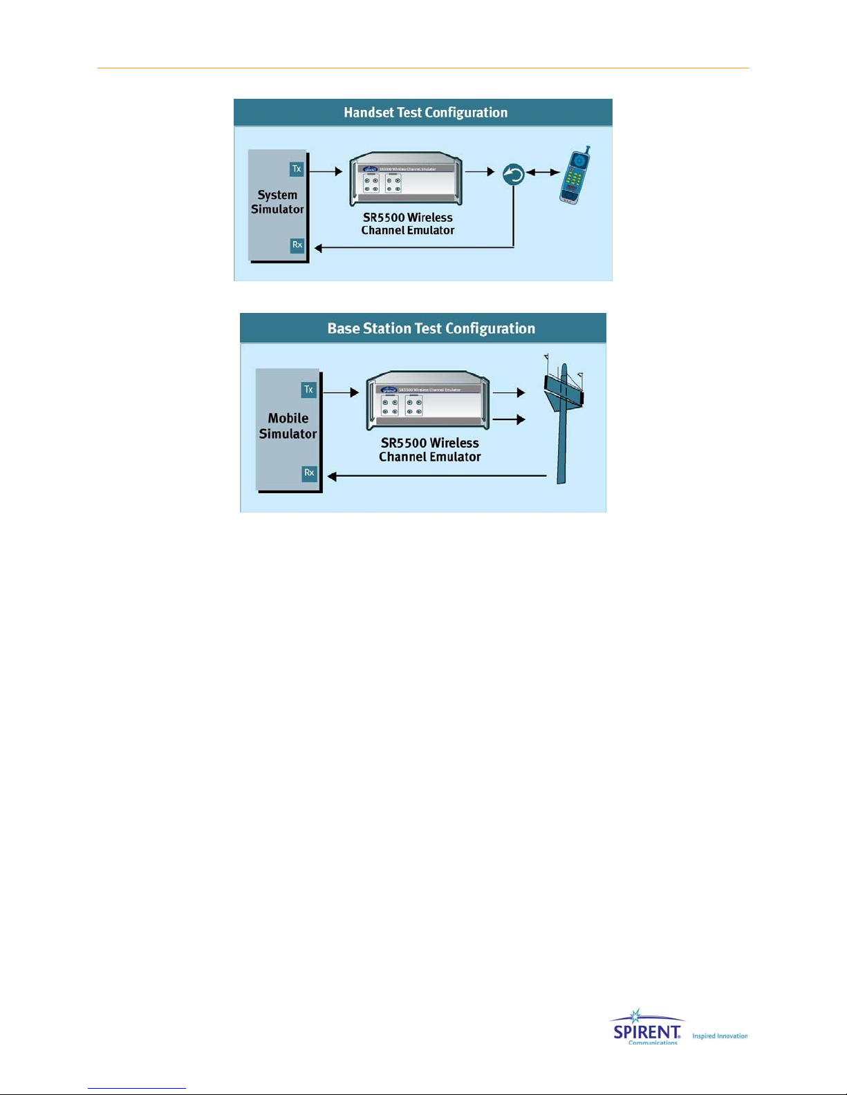
the ability to generate AWGN. The SR5500 can be utilized in both Handset and Base
Station test applications as shown in Figure 1-3 and Figure 1-4. These capabilities make
it possible for the SR5500 to play a valuable role in all phases of the product realization
cycle.
Chapter One: Introduction | 3
Figure 1-3: SR5500 Handset Test Setup
Figure 1-4: SR5500 Base Station Test Setup
1.2.1. Applicable to All Design Phases
Comprehensive performance evaluation throughout the product development cycle
improves the probability of identifying potential design issues at a stage where they can
be easily addressed. The SR5500 plays a valuable role throughout the product
realization process.
1.2.1.1 Research and Development
Early in the design and standardization of new air interface technologies, physical layer
modulation schemes, channel coding, and mobility algorithms must be evaluated and
compared. The SR5500 can analyze the performance of competing technologies by
providing repeatable test conditions across test campaigns. It is capable of sophisticated
channel models and low signal distortion, and can accommodate the evaluation of next-
generation, wide-bandwidth signal formats.

4 | SR5500 Operations Manual
1.2.1.2 Design Verification Test
Comprehensive evaluation of reference designs and commercial products against
original design objectives is a critical phase in the product realization process. You can
configure the SR5500 to emulate a wide range of radio propagation environments with
precise control over channel conditions for performance breakpoint analysis. With an
easy to use software application programming interface (API), the SR5500 also easily
integrates into automatic test systems capable of performing a large number of test
cases in minimal time.
1.2.1.3 Acceptance/Conformance Test
Before deployment, commercial products must typically undergo a series of acceptance
and conformance tests based on minimum industry performance standards. The
SR5500 User Interface features a Test Assistant that makes it easy to emulate
propagation conditions defined in various industry test specifications. These propagation
conditions are defined by ETSI, 3GPP, 3GPP2, and ITU.
1.2.1.4 System Performance Test
Once deployed to the field, the performance of wireless equipment is analyzed and
optimized. To accelerate the optimization process, it is necessary to recreate challenging
field scenarios on a controlled, repeatable test bed. By utilizing both RF channels in the
instrument, you can configure the SR5500 for bi-directional full duplex performance
evaluation. You can also program the SR5500 to play back field conditions repeatedly,
enabling the adjustment of algorithms until optimal performance is realized.
1.2.2. Evaluating Radio Access Technologies
The SR5500 possesses the capabilities necessary to evaluate a broad range of local and
wide area wireless network technologies. With frequency coverage up to 6 GHz, the
SR5500 covers all of the world’s deployment frequency bands. Supported technologies
include:
•GSM/GPRS/EDGE
•WCDMA
•WCDMA HSDPA
•CDMA2000 1x
•CDMA2000 1xEV-DO
•CDMA2000 1xEV-DV
•Location Based Services
•802.11.a/b/g
•802.16(WiMAX)
•HiperLAN

Chapter One: Introduction | 5
1.2.3. Evaluating Air Interface Performance
Radio access technologies possess layers of algorithms designed to mitigate the harsh
effects of radio propagation and to deliver seamless mobility. The SR5500 possesses the
critical features required to stress test air interface performance and to identify
opportunities to improve product design. The SR5500 can be used to evaluate and
improve the performance of:
•Baseband Demodulation
•Rake Finger Tracking
•Diversity Reception
•Channel Equalization
•Power Control Schemes
•Handover Efficiency
•Radio Link Protocols (RLPs)
•Geolocation
1.3. Key Product Features
1.3.1. Wireless Channel Emulation Features
With a powerful all-digital signal processing engine, the SR5500 emulates wideband
channel conditions with unprecedented accuracy and programmability. RF Channel
Emulation features include:
•Comprehensive channel models with up to 24 independent paths enables evaluation
of 3G and Wireless LAN equipment well beyond minimum performance standards.
•Real-time fading sequence generation enables channel model modifications without
the lengthy delays required to pre-calculate fading coefficients.
•Superior channel fidelity required to properly evaluate higher-order modulation
schemes, minimizing unwanted distortion that leads to false test results.
•Digital AWGN gives accurate and repeatable C/N, C/No, and Eb/No ratios.
•Creation of real-world fading scenarios with DEE (Dynamic Environment Emulation)
enables time-vary fading parameters.
•Long fading sequence repetition rate ensures realistic test conditions results.
•Time-varying channel models include dynamic Power Delay Profiles that evaluate
adaptive modulation and coding schemes.
•Real-time display of channel conditions and low-level control over channel model
playback.
•Frequency range extends to 6 GHz to cover 802.11a applications.
•Power meter capable of both continuous and triggered mode, ideal for bursty signals
like GSM/GPRS/EDGE and WLAN.
6 | SR5500 Operations Manual
1.3.2. Ease of Use Features
The SR5500 simplifies test setup and control with easy-to-use local and remote
interfaces. Some of these features include the ability to:
•Quickly recall industry standard fading profiles from 3GPP, 3GPP2, ITU and JTC.
•Create realistic user-defined scenarios using the SR5500 Channel Model Editor
providing easy access to emulation parameters.
•Set the absolute channel output level, without the need for external attenuators and
calibration, ensuring accurate signal levels are always present at the receiver under
test.
•Make real time changes to AWGN with the Interference Editor, eliminating the need
to re-configure the fading profile, significantly reducing test time.
•Monitor the Power Delay Profile and input/output power levels of the SR5500 in real-
time to provide valuable user feedback on current test conditions.
•Integrate the SR5500 into automatic test systems using a Windows .NET-based
software API.
1.4. SR5500 Guided Tour
All SR5500 functionality is controlled through the instrument control software SR5500
TestKit or the Application Programming Interface (API). Refer to the Setup Guide included
with the instrument for details on how to connect the SR5500 system.
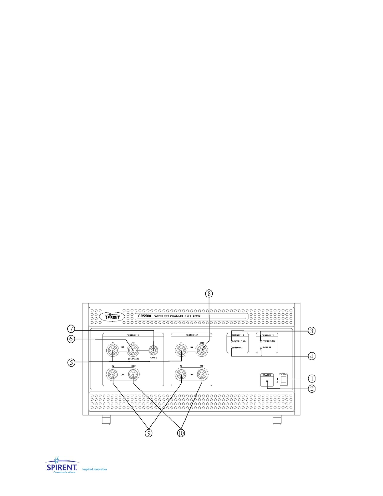
1.4.1. Front Panel Description
Figure 1-5: SR5500 Front Panel

Chapter One: Introduction | 7
Front Panel Control/Indicators
cPOWER Switch
The Power switch is located in the bottom right hand corner of the front panel.
dSTATUS LED
The Status LED is located next to the power switch and indicates the current status of the
unit. SR5500 is operating normally if the LED is green. An error condition exists when the
STATUS LED is red. The LED takes a few seconds to illuminate during power up.
eCHANNEL 1 OVERLOAD LED and CHANNEL 2 OVERLOAD LED
The LED indicates the RF input signal has peak levels above the permitted range and will be
clipped by the instruments input circuitry. The overload LEDs should be monitored to ensure
the signal applied at the RF Channel input is within the specified range.
fCHANNEL 1 BYPASS LED and CHANNEL 2 BYPASS LED
This indicator tells you the channel is in bypass mode. The channel is bypassed when the
LED is green.
Front Panel Signal Input/Output Connectors
gCHANNEL 1 and CHANNEL 2 RF IN
N Connector (50 Ω) - This connector functions as the channel RF input.
hCHANNEL 1 RF OUT [DUPLEX]
N Connector (50 Ω) - This connector functions as the channel 1 RF output.
iCHANNEL 1 RF OUT [OUT2]
N Connector (50 Ω) - Reserved for future use.
jCHANNEL 2 RF OUT
N Connector (50 Ω) - This connector functions as the channel 2 RF output.
kCHANNEL 1 and CHANNEL 2 LO IN
N Connector (50 Ω) - This connector functions as the channel local oscillator input. LO IN
must be connected to LO OUT via the Loop-back cable supplied with the SR5500.
lCHANNEL 1 and CHANNEL 2 LO OUT
N Connector (50 Ω) - This connector functions as the channel local oscillator output. LO IN
must be connected to LO OUT via the Loop-back cable supplied with the SR5500.
CAUTION: The RF IN and OUT Ports can accept a limited power range; refer to
the technical specifications to ensure absolute maximum levels are not
exceeded.

8 | SR5500 Operations Manual
1.4.2. Rear Panel Description
Figure 1-6: SR5500 Rear Panel
Rear Panel Controls
c10 MHz IN
BNC Type Connector (50 Ω) - Accepts an externally supplied 10 MHz sine wave reference
signal which can be used to drive the internal signal processing circuitry of the SR5500.
d10 MHz OUT
BNC Type Connector (50 Ω) - Provides a 10 MHz sine wave reference signal as an output.
eCH 1 and CH 2 I/IF IN
BNC Type Connector (50 Ω) - Reserved for future use.
fCH 1 and CH 2 Q IN
BNC Type Connector (50 Ω) - Reserved for future use.
gCH 1 and CH 2 I/IF OUT
BNC Type Connector (50 Ω) - Reserved for future use.
hCH 1 and CH2 Q OUT
BNC Type Connector (50 Ω) - Reserved for future use.
iDBB IN1, IN2, and IN3
26 Pin MDR Type Connector - Reserved for future use.
jDBB OUT
26 Pin MDR Type Connector - Reserved for future use.
kSYNC IN
15 Pin MDR Type Connector - Used to synchronize fading data between multiple SR5500
systems.
lSYNC OUT
15 Pin MDR Type Connector - Used to synchronize fading data between multiple SR5500
systems.
nCH 1 and CH 2 TRIG IN
BNC Type Connector (50 Ω) - Reserved for future use.

Chapter One: Introduction | 9
Rear Panel Controls
oCH 1 and CH 2 SYNC OUT
BNC Type Connector (50 Ω) - Reserved for future use.
pGPIB
Reserved for future use.
qETHERNET
RJ-45 Type Connector - The Ethernet port supports TCP/IP. It is recommended that a
Category 5 Ethernet cable be used.
rSERIAL
RJ-45 Type Connector - Control port used exclusively for configuring Ethernet
communication parameters.
sAUX 1
RJ-45 Type Connector - This port is used to control the SR5500 6 GHz(-EX) RF Converter.
tAUX 2
RJ-45 Type Connector - Reserved for future use.
uAC Power Receptacle
The AC universal power receptacle is located on the lower left corner of the rear panel. This
receptacle also contains the fuses for the unit.
1.5. Quick Start Procedure
To prepare the SR5500 for initial operation, perform the following steps. Refer to the
table below to determine the number of cartons in the SR5500 shipment.
1. Unpack the SR5500 shipping cartons. There should be two shipping cartons, one
containing the SR5500 and accessories and the other containing the PC. An optional
third carton contains the SR5500 6 GHz(-EX) RF Converter and accessories.
a. The cartons should contain a packing list detailing all the items in the cartons.
b. Make sure that all parts listed on the packing list are contained in your SR5500
shipping cartons.
c. Save the shipping cartons and packing materials until you have completed the
system installation and initial check. If you must return equipment, please use
the original box and packing material.
d. Check each item for physical damage. If any part appears to be damaged, contact
the Spirent Communications Customer Service department.
2. Plug one end of the supplied AC power cord into the rear panel, and then plug the
other end into your AC source. Repeat as necessary.
3. Connect supplied loop-back cables from LO IN CH1 to LO OUT CH1. Repeat for LO
CH2.
4. OPTIONAL: Connect the following cables between the SR5500 and the SR5500 6
GHz(-EX) RF Converter.
(From) SR5500 (To) 6 GHz(-EX) RF Converter Cable Used
CHANNEL 1 RF IN IF - CH1 OUT Supplied N-N cable
CHANNEL 1 RF OUT IF - CH1 IN Supplied N-N cable
10 | SR5500 Operations Manual
(From) SR5500 (To) 6 GHz(-EX) RF Converter Cable Used
CHANNEL 2 RF IN IF - CH2 OUT Supplied N-N cable
CHANNEL 2 RF OUT IF - CH2 IN Supplied N-N cable
AUX 1 (Unlabeled RJ-45 connector on
rear panel)
RJ-45 Cable
5. Connect the supplied cross over cable from the PC built-in Ethernet port (not the PC
Card Ethernet Port), to the SR5500 Ethernet port on the rear panel. Optionally, you
can connect the PC Card Ethernet Port to the LAN.
NOTE: When connecting the 6 GHz(EX) RF connector to the SR5500 the supplied
N, N cables must be used in order to maintain level accuracy.
6. Turn the power on.
e. Set the AC power switch on the lower right corner of the front panel to the "|"
position. The SR5500 now executes its power-up self test and calibration
sequence, this takes a few seconds. You will hear two beeps and the status light
will illuminate green. Note: The STATUS Light will take a few seconds before
turning on.
f. OPTIONAL: If the SR5500 6 GHz(-EX) RF Converter is present, turn the power on
by setting the AC power switch to the “|” position on the rear of the unit.
g. Power on the PC. Refer to the PC documentation for details.
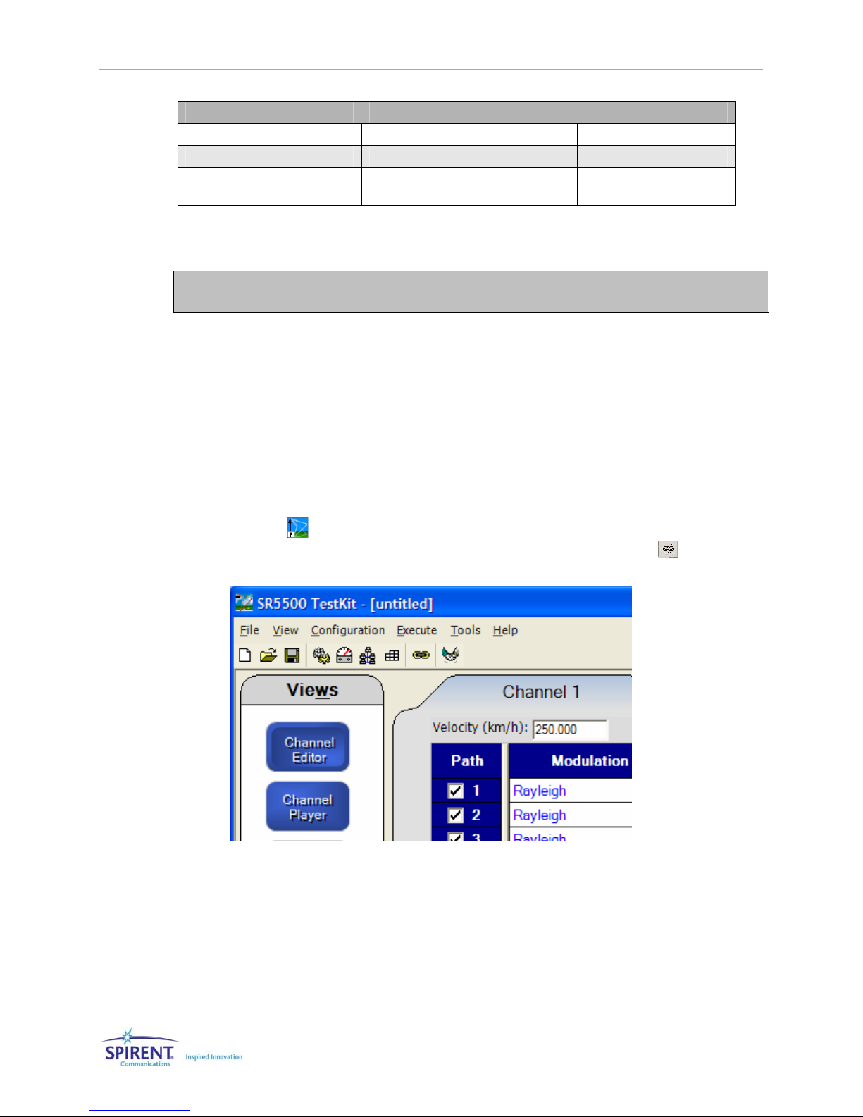
7. Launch the instrument control software SR5500 TestKit on the PC by clicking the
TestKit icon on the desktop. After launching the SR5500 TestKit application,
complete the connection to the SR5500 by clicking the Connect icon shown in
Figure 1-7.
Figure 1-7: SR5500 TestKit Software Menus
8. TestKit indicates the connected status by displaying Status: Connected in the status
bar at the bottom of the window as shown in Figure 1-8.

Chapter One: Introduction | 11
Figure 1-8: Status Connected Indicator
1.6. Verification Procedure
This procedure verifies the basic operation of the SR5500. It is not necessary to
complete these steps to use the SR5500. A signal generator and spectrum analyzer
capable of operating at 900 MHz is needed for this verification. The SR5500 default
settings are used for this procedure. Use the table and block diagram below to connect
the required equipment.
Connect From Connect To Cable
Signal Generator Output SR5500 CHANNEL 1 RF IN N to N
SR5500 CHANNEL 1 RF OUT Spectrum Analyzer Input N to N
Signal
Generator
SR5500 Spectrum
Analyzer
CH1
RF In CH1
RF Out
Figure 1-9: SR5500 Verification Setup Diagram
OPTIONAL: Use the table and block diagram shown in Figure 1-10 to
connect the equipment to a SR5500 equipped with the 6 GHz(EX) RF
Converter.
Connector 1 (From) Connector 2 (To) Cable
Signal Generator Output SR5500 6 GHz(-EX) RF Converter
CH 1 RF IN
N-Type
SR5500 6 GHz(-EX) RF Converter CH
1 RF OUT
Spectrum Analyzer Input N-Type
CH1 In CH1 Out
Signal
Generator SR5500 Spectrum
Analyzer
6GHz Option
Figure 1-10: SR5500 with 6GHz (-EX) Option Verification Setup
12 | SR5500 Operations Manual
To run the Verification Procedure:
1. Set the signal generator to 900 MHz with an output power of -10 dBm.
2. Set the spectrum analyzer to 900 MHz with a span of 30 MHz.
3. The output signal should be about -40 dBm, as in the spectrum analyzer display
shown in Figure 1-11.
Figure 1-11: Spectrum Analyzer Output Signal of SR5500 at 900 MHz
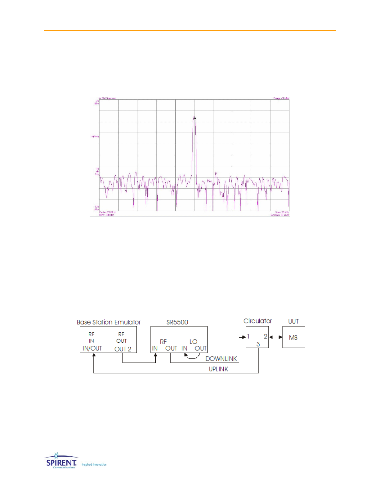
1.7. Quick Start Using Test Assistant
This procedure uses the Test Assistant to step through an example of a GSM standard
Specification Test. Test Assistant automatically configures the SR5500 for the specific
test application.
A Base Station Emulator, circulator, and a DUT (GSM Mobile) are used for this procedure.
Figure 1-12 shows the setup for the Mobile Test.
Figure 1-12: Mobile Test Setup
1. Connect the Base Station Emulator RF Output Port to the Channel 1 RF IN of the
SR5500 with the appropriate cable.
2. From Channel 1 RF OUT on the SR5500 connect to Port 1 of a Circulator, using the
appropriate cable.
Table of contents
Popular Conference System manuals by other brands


Aiphone
Aiphone NHX SYSTEM series Operation manual

Federal Signal Corporation
Federal Signal Corporation Atkinson Dynamics AD-26 Installation and maintenance manual

Foxpro
Foxpro SNOW COMMANDO instruction manual

LifeSize
LifeSize Express user guide

Honeywell Home
Honeywell Home PROLTE Series Installation and setup guide

Panasonic
Panasonic KX-HTS Series Setup Reference Guide


