manuals.online logo
Brands
  1. Home
  2. •
  3. Brands
  4. •
  5. Spirent
  6. •
  7. Computer Hardware
  8. •
  9. Spirent Vertex User manual

Spirent Vertex User manual

+1 800-SPIRENT – www.spirent.com
Spirent Setup Guide:
Information subject to change.
71-007894.A10
Vertex Channel Emulator
Page 1 of 9
Equipment Layout
Instructions
1 Ensure the AC power cords are not connected to wall outlets.
2 Connect the rear panel cables by following the instructions on the following page:
- For a single-Vertex configuration, see page 2.
- For a dual-Vertex configuration, see page 3.
- For a quad-Vertex configuration, see page 4.
3 Connect the front panel cables by following the instructions on the following page:
- For a dual-Vertex configuration, see page 5.
- For a quad-Vertex configuration, see page 6.
4For a quad-Vertex configuration, make sure there is adequate open space on the sides of
the rack. See page 7 for more information.
5 Make sure the loopback cable is connected on the rear panel.
6Connect the power cords to all instruments and apply power to the system by following the
instructions on page 8.
7 Start the Vertex Channel Emulator application by following the instructions on page 9.
Assembly Procedure
Item Quantity
Vertex Channel Emulator 1
Vertex power supply 1
Ethernet cable (loopback cable) 1
Controller laptop 1
Laptop power supply 1
System Components
Controller laptop
Attention!
You MUST connect the loopback
cable from the right side
Ethernet port of the embedded
PC to Ethernet port 2 of the
DSPM board at slot1 before you
apply power to the system.
Ethernet port 2 of
DSPM board
Ethernet port of
embedded PC
Loopback
cable
+1 800-SPIRENT – www.spirent.com
Spirent Setup Guide:
Information subject to change.
71-007894.A10
Vertex Channel Emulator
Page 2 of 9
Single-Vertex Configuration:
Rear Panel Cable Routing
E1 LAN Cable
VGA
U1 USB to RS-232 USB
USB
Supplied by User
E2 LAN Cable
+1 800-SPIRENT – www.spirent.com
Spirent Setup Guide:
Information subject to change.
71-007894.A10
Vertex Channel Emulator
Page 3 of 9
E1 LAN Cable
E2 LAN Cable
E3 LAN Cable
B1 BNC cable
M3 MINI SAS
cable
M4 MINI SAS
cable
H1 HDMI
cable
Vertex 1: Primary
Vertex 2: Secondary
M5 MINI SAS
cable
M6 MINI SAS
cable
Dual-Vertex Configuration:
Rear Panel Cable Routing
E4 LAN Cable
E5 LAN Cable
+1 800-SPIRENT – www.spirent.com
Spirent Setup Guide:
Information subject to change.
71-007894.A10
Vertex Channel Emulator
Page 4 of 9
M6
M8
M10
M12
M7
M9
M11
M13
M14 M15
M16
M17
M18 M19
M20
M21
H1
H2
H3
B1
B3
B2
Controller PC
E1
E2
E3
E5
E6
E4
Ethernet cable
Quad-Vertex Configuration:
Rear Panel Cable Routing
Vertex1
Vertex2
VBS
Vertex3
Vertex4
+1 800-SPIRENT – www.spirent.com
Spirent Setup Guide:
Information subject to change.
71-007894.A10
Vertex Channel Emulator
Page 5 of 9
Vertex 1: Primary
Vertex 2: Secondary
M1 MINI SAS
cable M2 MINI SAS
cable
Dual-Vertex Configuration:
Front Panel Cable Routing
Secondary SYNC IN
Primary SYNC OUT2
Primary SYNC IN
Primary SYNC OUT1
+1 800-SPIRENT – www.spirent.com
Spirent Setup Guide:
Information subject to change.
71-007894.A10
Vertex Channel Emulator
Page 6 of 9
M1
M2
M3
M4
M5
Quad-Vertex Configuration:
Front Panel Cable Routing
Vertex1
Vertex2
VBS
Vertex3
Vertex4
+1 800-SPIRENT – www.spirent.com
Spirent Setup Guide:
Information subject to change.
71-007894.A10
Vertex Channel Emulator
Page 7 of 9
Vertex1
Vertex2
VBS
Vertex3
Vertex4
Rack 40U
R40-VCE6-01
(53-005278)
Attention!
The rack has a mesh panel
on each side for ventilation.
You MUST keep at least
20cm of open space on each
side of the rack.
Quad-Vertex Configuration:
Rack Mounting
+1 800-SPIRENT – www.spirent.com
Spirent Setup Guide:
Information subject to change.
71-007894.A10
Vertex Channel Emulator
Page 8 of 9
Applying Power to the System
1 Make sure the loopback cable is connected on the rear panel of the Vertex instrument.
2For a quad-Vertex configuration, connect the power cord to the power connector on the rear panel of
the VBS, plug the power cord directly into the wall outlet, and then power up the VBS.
NOTE: For a quad-Vertex configuration, you MUST wait 30 seconds before proceeding to the next step
to power up Vertex1.
3 Connect the AC power cord to the power connector on the rear panel of the Vertex instrument.
NOTE: If this is a multi-Vertex configuration, start with Vertex1, which is the top unit.
4 Plug the power cord directly into the wall outlet on an individual branch circuit.
5 Press the power switch on the rear panel of the Vertex instrument.
6 Press the power switch on the front panel of the Vertex instrument.
The LED above the power switch changes from solid orange to blinking green. Blinking green indicates
that the instrument is booting up.
After the instrument boots up, the LED changes to solid green.
7 Repeat Steps 1 through 6 for each Vertex instrument.
NOTE: For a quad-Vertex configuration, you MUST power up the Vertex instruments in sequence
(that is, Vertex1, Vertex2, Vertex3, and then Vertex4).
Power Connection Procedure
Instructions
Perform the following steps after you have completed all cable
routing on the rear panel and the front panel.
NOTE:
If the AC power voltage is <200V, make sure to connect a 20A power cord
to Vertex.
20A Receptacle
Attention!
You MUST connect the loopback
cable from the right side
Ethernet port of the embedded
PC to Ethernet port 2 of the
DSPM board at slot1 before you
apply power to the system.
Ethernet port 2 of
DSPM board
Ethernet port of
embedded PC
Loopback
cable
+1 800-SPIRENT – www.spirent.com
Spirent Setup Guide:
Information subject to change.
71-007894.A10
Vertex Channel Emulator
Page 9 of 9
1
2
3
1 On the Controller laptop, double-click on the Vertex Channel Emulator desktop shorcut.
2In the Primary Fader IP Address box, type in the IP address of the Vertex instrument, and then click the
Connect button.
The Vertex window appears.
3 From the Help menu, select Manuals>Vertex Manual to access the user manual.
Starting the Vertex Application
Instructions

Other manuals for Vertex

4

Other Spirent Computer Hardware manuals

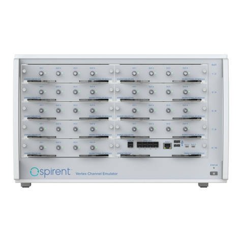
Spirent Vertex Installation and operating instructions

Spirent

Spirent Vertex Installation and operating instructions

Spirent Vertex Installation and operating instructions

Spirent

Spirent Vertex Installation and operating instructions

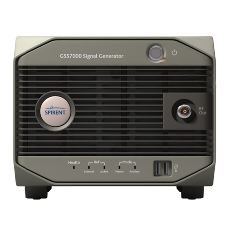
Spirent GSS7000 User manual

Spirent

Spirent GSS7000 User manual

Spirent Vertex Installation and operating instructions

Spirent

Spirent Vertex Installation and operating instructions

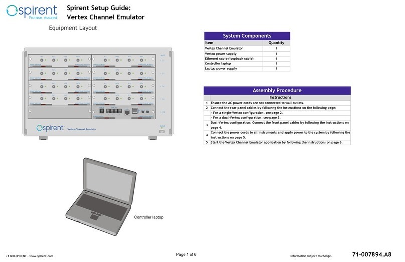
Spirent Vertex Channel Emulator User manual

Spirent

Spirent Vertex Channel Emulator User manual

Popular Computer Hardware manuals by other brands

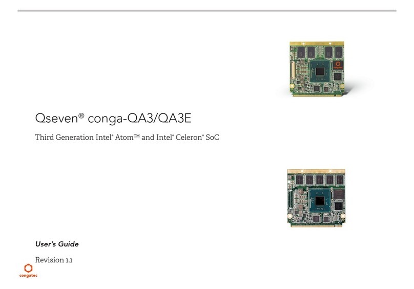
Congatec conga-QA3 user guide

Congatec

Congatec conga-QA3 user guide

CompuLab UCM-iMX93 reference guide

CompuLab

CompuLab UCM-iMX93 reference guide

LSI 3ware 9750 installation guide

LSI

LSI 3ware 9750 installation guide

CNET CWC-854 user manual

CNET

CNET CWC-854 user manual

Intel RS2BL080 - RAID Controller Configuration guide

Intel

Intel RS2BL080 - RAID Controller Configuration guide

Rosewill RCX-Z755-EX user manual

Rosewill

Rosewill RCX-Z755-EX user manual

American Megatrends MegaRAC 780 Series Features

American Megatrends

American Megatrends MegaRAC 780 Series Features

IEI Technology KINO-AH611 Quick installation guide

IEI Technology

IEI Technology KINO-AH611 Quick installation guide

Rabbit RabbitCore RCM2200 user manual

Rabbit

Rabbit RabbitCore RCM2200 user manual

FETtec Mini AIO 15A manual

FETtec

FETtec Mini AIO 15A manual

Alphacool CORE DISTRO PLATE Series quick start guide

Alphacool

Alphacool CORE DISTRO PLATE Series quick start guide

turck MS96-11EX0-R/115VAC operating manual

turck

turck MS96-11EX0-R/115VAC operating manual

YASKAWA CP 040 RS422/485 manual

YASKAWA

YASKAWA CP 040 RS422/485 manual

Cypress Semiconductor CY7C2563KV18 Configurations

Cypress Semiconductor

Cypress Semiconductor CY7C2563KV18 Configurations

Waves MaxxBass 102 user guide

Waves

Waves MaxxBass 102 user guide

VIPA System 200V Series manual

VIPA

VIPA System 200V Series manual

Matrix Orbital LCD2041 Technical manual

Matrix Orbital

Matrix Orbital LCD2041 Technical manual

Peak PCAN-miniPCIe FD user manual

Peak

Peak PCAN-miniPCIe FD user manual

manuals.online logo
manuals.online logoBrands
  • About & Mission
  • Contact us
  • Privacy Policy
  • Terms and Conditions

Copyright 2025 Manuals.Online. All Rights Reserved.