Spirent Vertex User manual

Vertex®High Frequency Converter
Release 2.0
User Guide

Vertex High Frequency Converter
Release 2.0 – User Guide
www.spirent.com 2
© 2019 Spirent Communications, Inc. All Rights Reserved.
All of the company names and/or brand names and/or product names referred to in this document, in
particular, the name “Spirent” and its logo device, are either registered trademarks or trademarks of
Spirent plc and its subsidiaries, pending registration in accordance with relevant national laws. All other
registered trademarks or trademarks are the property of their respective owners. The information
contained in this document is subject to change without notice and does not represent a commitment on
the part of Spirent Communications. The information in this document is believed to be accurate and
reliable; however, Spirent Communications assumes no responsibility or liability for any errors or
inaccuracies that may appear in the document.
Page Part Number: 71-008798, Version A1

Vertex High Frequency Converter
Release 2.0 – User Guide
www.spirent.com 3
Safety Summary
If the equipment is used in a manner not specified by the manufacturer the protection
provided by the equipment may be impaired.
Safety Symbols
The following safety symbols are used throughout this manual and may be found on
the instrument. Familiarize yourself with each symbol and its meaning before
operating this instrument.
Instruction manual symbol. The
product is marked with this symbol
when it is necessary for you to refer
to the instruction manual to protect
against damage to the instrument.
Frame terminal. A connection
to the frame (chassis) of the
equipment which normally
includes all exposed metal
structures.
Protective ground (earth) terminal.
Used to identify any terminal which
is intended for connection to an
external protective conductor for
protection against electrical shock
in case of a fault, or to the terminal
of a protective ground (earth)
electrode.
The caution sign denotes a
hazard. It calls attention to an
operating procedure, practice,
condition or the like, which, if
not correctly performed or
adhered to, could result in
damage to or destruction of
part or all of the product or
your data.
Indicates dangerous voltage
(terminals fed from the interior by
voltage exceeding 1000 volts must
be so marked).
Alternating current (power
line).
Symbol when movement with two
people is required. When this
symbol is noted on our product, two
people are required to move it
without accident.

Vertex High Frequency Converter
Release 2.0 – User Guide
www.spirent.com 4
Résumé des règles de sécurité
Si le matériel est utilisé d’une façon non conforme aux spécifications du
constructeur, la protection assurée par le matériel peut être mise en défaut.
Symboles de sécurité
Les symboles suivants sont utilisés dans tout le manuel et peuvent être trouvés sur
le matériel. Il est recommandé de se familiariser avec chaque symbole et sa
signification avant de manipuler le matériel.
Symbole « manuel d’instruction ».
Ce symbole apparaît sur le produit
lorsqu’il est nécessaire de se
référer au manuel d’instruction pour
éviter une détérioration du matériel.
Masse. Ce symbole identifie
une connexion au châssis du
matériel (ce châssis inclut
normalement toutes les
structures métalliques
exposées).
Terre : ce symbole identifie la
connexion de terre chargée de
protéger le matériel contre les
chocs électriques. Cette connexion
doit être raccordée vers un
conducteur externe de protection
ou vers une électrode de type terre.
Ce symbole désigne une
opération ou une condition
dite « sensible », qui, si elle
n’est pas correctement
réalisée, pourrait entraîner de
sérieuses détériorations au
matériel ou aux données
utilisateur.
Ce symbole indique un voltage
dangereux (connexion alimentée
en interne par un voltage excédant
1000 volts).
Courant alternatif (ligne de
puissance).
Symbole de déplacement avec
deux personnes requises. Lorsque
ce symbole est noté sur notre
produit, deux personnes sont
requises afin de le déplacer sans
accident

Vertex High Frequency Converter
Release 2.0 – User Guide
www.spirent.com 5
Table of Contents
1. Introduction........................................................................................7
Overview .............................................................................................................. 7
Vertex HFC Diagram ............................................................................................ 8
Connector Descriptions ........................................................................................ 9
4-Channel Vertex HFC Connectors ........................................................... 9
20-Channel Vertex HFC Connectors ....................................................... 10
Indicator Descriptions......................................................................................... 11
Installation Options............................................................................................. 11
Bench-Top Configuration......................................................................... 11
Rack-Mount Configuration ....................................................................... 11
Ventilation........................................................................................................... 12
How to Contact Us.............................................................................................. 13
Access the Latest Documentation ...................................................................... 14
Documentation Conventions .............................................................................. 14
2. Care and Maintenance ....................................................................15
Cleaning ............................................................................................................. 15
3. Replacing the Fuse..........................................................................16
Overview ............................................................................................................ 16
Procedure........................................................................................................... 16
Remplacement du Fusible du Vertex HFC Fuse ................................................ 18
4. Technical Specifications ..................................................................19
Overview ............................................................................................................ 19
4-Channel Vertex HFC ....................................................................................... 19
20-Channel Vertex HFC ..................................................................................... 20
Interface and Environment Characteristics......................................................... 21
Front Panel Indicators.............................................................................. 21
Power Requirements ............................................................................... 21
Operating Environment............................................................................ 21
Dimensions and Weight........................................................................... 21
Les Indicateurs du Panneau Avant.......................................................... 22
Exigences en Matière d'Alimentation....................................................... 22


Vertex High Frequency Converter
Release 2.0 – User Guide
www.spirent.com 7
1. Introduction
Overview
Spirent Vertex®High Frequency Converter (Vertex HFC) extends the Vertex channel
emulator frequency range from radio frequency (RF) band to higher millimeter wave
frequency (mmW) band for 5G applications. Vertex HFC converts the signal between
RF <6GHz and mmW frequency.
Two models of the Vertex HFC are available:
•4-channel model (VCE6-HFC-4C)
•20-channel model (VCE6-HFC-20C)
Figure 1. 4-Channel Vertex HFC.
Figure 2. 20-Channel Vertex HFC.

Vertex High Frequency Converter
Release 2.0 – User Guide
www.spirent.com 8
Vertex HFC Diagram
There is mixer on each conversion link in Vertex HFC. The RF frequency signal is
mixed with the signal from internal LO or external LO and then converted to mmW
frequency. The signal from mmW frequency is also converted to RF frequency with
the same LO. At each input/output (I/O) port, an RF and mmW filter is used to filter
out outband spurious emission or interference.
mmW
I/O
Mixer
RF
Filter
mmW
Filter
LO Distributor
Internal LO
LO Jumper
Amplifier
RF
I/O
AC
Power
Module
Figure 3. 4-Channel Vertex HFC Diagram.
mmW eNB I/O 1
Mixers
RF
Filter
LO Distributor
Internal LO
LO Jumper
Amplifier
RF eNB I/O 1
mmW
Filter
mmW eNB I/O 16 RF eNB I/O 16
mmW UE I/O 1
mmW UE I/O 4
mmW UE I/O 3
mmW UE I/O 2
mmW eNB I/O 2 RF eNB I/O 2
RF UE I/O 1a
RF UE I/O 1b
RF UE I/O 2a
RF UE I/O 2b
RF UE I/O 3a
RF UE I/O 3b
RF UE I/O 4a
RF UE I/O 4b
External 10MHz Ref
AC
Power
Module
Figure 4. 20-Channel Vertex HFC Diagram.

Vertex High Frequency Converter
Release 2.0 – User Guide
www.spirent.com 9
Connector Descriptions
This section describes the front panel connectors and rear panel connectors on both
models of Vertex HFC.
4-Channel Vertex HFC Connectors
The 4-channel Vertex HFC provides the following connectors on the front panel:
•mmW I/O ports (4 ports) – Connects to mmW frequency devices
•RF I/O ports (4 ports) – Connects to RF frequency devices
Figure 5. 4-Channel Vertex HFC front panel.
The 4-channel Vertex HFC provides the following connectors on the rear panel:
•LO IN port – Connects to external LO if needed
•LO OUT port – Send out LO from internal oscillator
•10MHz Ref IN – Connects to external 10MHz reference clock
NOTE:
The external 10MHz reference signal must be a CW wave signal. There will be a
frequency stability issue if the reference signal is a square wave.
LO OUT
LO IN 10MHz Ref IN
Figure 6. 4-Channel Vertex HFC rear panel.

Vertex High Frequency Converter
Release 2.0 – User Guide
www.spirent.com 10
20-Channel Vertex HFC Connectors
The 20-channel Vertex HFC provides the following connectors on the front panel:
•mmW I/O ports (20 ports) – Connects to mmW frequency devices
•RF I/O ports (24 ports) – Connects to RF frequency devices
Figure 7. 20-Channel Vertex HFC front panel.
The 20-channel Vertex HFC provides the following connectors on the rear panel:
•LO IN port – Connects to external LO if needed
•LO OUT port – Send out LO from internal oscillator
•10MHz Ref IN – Connects to external 10MHz reference clock
NOTE:
The external 10MHz reference signal must be a CW wave signal. There will be a
frequency stability issue if the reference signal is a square wave.
LO OUT
LO IN 10MHz Ref IN
Figure 8. 20-Channel Vertex HFC rear panel.

Vertex High Frequency Converter
Release 2.0 – User Guide
www.spirent.com 11
Indicator Descriptions
Vertex HFC provides the following LED indicators on the front panel:
•POWER – Solid green if the power is on.
•STATUS – Solid green if Vertex HFC is locked successfully to the external
10MHz reference clock
Installation Options
You can install Vertex HFC in the following configurations:
•Bench-top configuration
•Rack-mount configuration
Bench-Top Configuration
Vertex HFC is typically used in a bench-top configuration along with a Vertex
channel emulator and other equipment. The instructions for cabling and connecting
Vertex HFC are provided in the Spirent Vertex®High Frequency Converter Setup
Guide, 71-008347, Version A1. The cabling and connections are the same as for a
rack-mounted installation.
CAUTION!
When using Vertex HFC in a bench-top configuration, make sure the power-cord
connection is accessible at all times in case an emergency power disconnection is
required.
Rack-Mount Configuration
You can install Vertex HFC in a rack with a Vertex channel emulator and other
equipment. The instructions for cabling and connecting Vertex HFC are provided in
the Spirent Vertex®High Frequency Converter Setup Guide, 71-008347, Version A1.
Contact Spirent for more information regarding a rackmount setup.

Vertex High Frequency Converter
Release 2.0 – User Guide
www.spirent.com 12
Ventilation
For proper ventilation, ensure that the rack is located in an area with the following
conditions:
•A minimum of 18 inches of space between the sides of the rack and any objects
that may restrict air flow. For example, a wall, cabinet, or another rack.
•A minimum of 12 inches of space between the rear door and any object that may
restrict air flow (for example, a wall, cabinet, or another rack).
•Make sure there is nothing that blocks the airflow from the exhaust fans on the
top of the rack.
•Do not allow other equipment to exhaust into the rack, as this may cause the
equipment to overheat.
•If insufficient ventilation is provided, the equipment in the rack may overheat.
This can cause improper operation.
Refer to “Technical Specifications” on page 19 for information about the required
operating temperature.

Vertex High Frequency Converter
Release 2.0 – User Guide
www.spirent.com 13
How to Contact Us
To obtain technical support for any Spirent Communications product, please contact
our Support Services department using any of the following methods:
Americas
E-mail: [email protected]
Web: http://support.spirent.com
Toll Free: +1 800-SPIRENT (+1 800-774-7368) (North America)
Hours: Monday through Friday, 05:30 to 18:00 Pacific Time
Europe, Africa, Middle East
E-mail: [email protected]
Web: http://support.spirent.com
EMEA Phone: +33 (1) 6137 2270
UK Phone: +44 1803 546333
Toll Free Phone: +1 818-676-2616
Hours: Monday through Thursday, 09:00 to 18:00, 9:00 to 17:00 Friday, Paris Time
Asia Pacific
E-mail: [email protected]
Web: http://support.spirent.com
In China Mainland Phone: +86 (400) 810-9529 (toll-free)
Out of China Mainland Phone: +86 (10) 8233 0033
India: 1800-419-2111
Operating Hours: Monday through Friday, 09:00 to 18:00 Beijing Time
The Spirent Knowledge Base (http://support.spirent.com) is designed to serve
your technical information needs. The Knowledge Base gives you access to tens of
thousands of documents that help answer your network analysis and measurement
questions. New content is added daily by Spirent’s communications and networking
experts. Sign in with your user ID and password to gain access to additional content
that is available only to customers – user manuals, Help files, release notes, Tech
Bulletins, and more. When you sign in, you can also use the Knowledge Base to
download software and firmware, and to manage your SRs.
Information about Spirent Communications and its products and services can be
found on the main company website at http://www.spirent.com.
Company Address
Spirent Communications, Inc.
26750 Agoura Road
Calabasas, CA 91302
USA
Vertex High Frequency Converter
Release 2.0 – User Guide
www.spirent.com 14
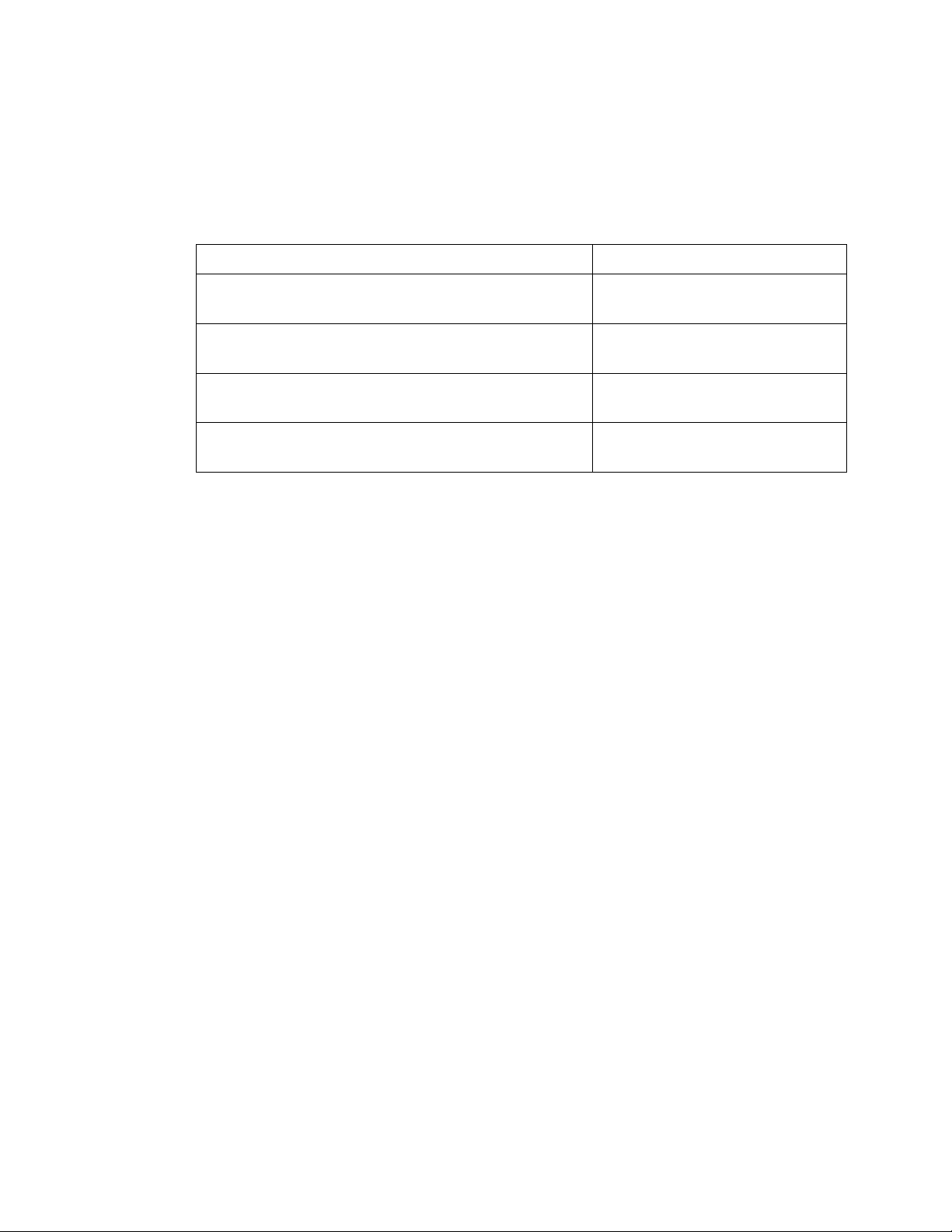
Access the Latest Documentation
The following table lists the documentation related to Vertex HFC Release 2.0. You
can access these documents from the Spirent Customer Service Center website:
http://support.spirent.com.
Document
Part Number
Spirent Vertex®High Frequency Converter
Release 2.0.1 System Release Summary
71-008861, Version A0
Spirent Vertex®High Frequency Converter
Release 2.0 System Release Summary
71-008799, Version A0
Spirent Vertex®High Frequency Converter Setup
Guide
71-008347, Version A1
Spirent Vertex®High Frequency Converter
Release 2.0 User Guide
71-008798, Version A1
To access the latest versions of these documents, perform the following steps:
1. Log into the Spirent Customer Service Center website
(http://support.spirent.com) using the email address and password assigned to
you by Spirent.
2. In the Search Knowledge Base box, enter DOC11683and click on Search KB.
The Spirent Vertex High Frequency Converter Documentation page appears.
3. In the Documentation section, click on the link for the document in which you are
interested.
The page for the selected document appears.
4. Click on the link in the Attachment area to view the corresponding PDF.
Documentation Conventions
This document uses the following conventions:
•Text you type appears in this type style
•Keyboard keys are displayed IN THIS TYPE STYLE

Vertex High Frequency Converter
Release 2.0 – User Guide
www.spirent.com 15
2. Care and Maintenance
Cleaning
Cleaning Vertex HFC is typically not required. However, for good RF performance, it
is important to keep the RF connectors on the front and rear panels free of dust and
debris. Also, for proper internal airflow, ensure that the fan vent on the rear panel is
clear of debris and not blocked by an object.

Vertex High Frequency Converter
Release 2.0 – User Guide
www.spirent.com 16
3. Replacing the Fuse
Overview
This section describes how to replace the fuse in Vertex HFC.
CAUTION!
Do not open Vertex HFC. It contains no internal user serviceable parts.
Procedure
CAUTION!
Disconnect the power cord before replacing fuses.
Perform the following steps to replace fuses in Vertex HFC:
1. Unplug the Vertex HFC power cord from the wall outlet, or unplug the power cord
from the receptacle on the rear panel of Vertex HFC.
The fuses are installed at the factory to match the most commonly used line
voltage in the country of destination.
CAUTION!
Disconnect the power cord from the supply before servicing the unit.
2. Locate the power entry module on the rear panel.
3. Using a small screwdriver, pry out the fuse holder using the notch located at the
top of the power entry module. Refer to the following figure.

Vertex High Frequency Converter
Release 2.0 – User Guide
www.spirent.com 17
4. Pull the fuse from the fuse holder as shown in the previous figure.
5. To reinstall a fuse, select the proper fuse, and place the fuse in the fuse holder.
Part Number
Type
1800-3703 2A 250V Time-Lag (Slow-Blow) Fuse
6. Reinsert the fuse holder into the power entry module.
7. Reconnect the power cord.
8. Proceed with normal power up.
NOTE:
If the fuses blow again, disconnect the power cord, and do not use Vertex HFC.
Contact Spirent Global Services at http://support.spirent.com.
See “How to Contact Us” on page 13 for more information about contacting
Spirent Global Services.

Vertex High Frequency Converter
Release 2.0 – User Guide
www.spirent.com 18
Remplacement du Fusible du Vertex HFC Fuse
ATTENTION!
Débrancher le cordon d'alimentation avant de remplacer les fusibles.
Procédez comme suit pour remplacer les fusibles:
1. Débranchez le cordon d'alimentation du Vertex HFC de la prise murale, ou
débranchez le cordon d'alimentation de la prise électrique sur le panneau arrière
du Vertex HFC.
Les fusibles sont installés à l'usine en fonction de la tension de ligne les plus
couramment utilisés dans le pays de destination.
ATTENTION!
Débrancher le cordon d'alimentation de l'alimentation avant de procéder à
l'entretien de l'appareil.
2. Localiser le module d'entrée d'alimentation sur le panneau arrière.
3. Avec un petit tournevis, faire levier sur le porte-fusible à l'aide de l'encoche
située en haut de la module d'entrée d'alimentation. Reportez-vous au schéma
suivant:
4. Tirez le fusible du porte-fusible comme indiqué ci-dessus dans la figure.
5. Pour remise en état, sélectionner le fusible approprié et le placer sur le support.
Numero du Composant
Type
1800-3703 2A 250V Time-Lag (Slow-Blow) Fusible
6. Réinstaller le support de fusible dans le module d’entrée d’alimentation.
7. Rebranchez le cordon d'alimentation.
8. Procéder à la mise sous tension normale.

Vertex High Frequency Converter
Release 2.0 – User Guide
www.spirent.com 19
4. Technical Specifications
Overview
This section provides the technical specifications for Vertex HFC.
NOTE:
All technical specifications are typical and subject to change without notice. Unless
otherwise indicated, the specifications are measured at room temperature, and the
instrument has been booted up for more than 30 minutes.
4-Channel Vertex HFC
Frequency
Range
5.9 - 10GHz 9 - 13GHz 24.25 - 29.5GHz 37 - 40.5GHz
Model
Number
VCE6-HFC-
4C-7GHz
VCE6-HFC-
4C-11GHz
VCE6-HFC-4C-
27GHz
VCE6-HFC-4C-
39GHz
LO
11.75GHz
14.5GHz
23. 5GHz
35GHz
External LO
level
4dBm 4dBm 4dBm 4dBm
Internal RF
filter
DC-6GHz DC-6GHz DC-6GHz DC-6GHz
Internal
mmWave
filter
5.9-10GHz 9-13GHz 24.25 to 29.5GHz 37 to 40.5GHz
Input
frequency
1.75 to
5.85GHz
1.5 to
5.5GHz
0.75 to 6GHz 2 to 5.5GHz
Maximum
input power
level to any
RF/mmWave
port
<27.5dBm <27.55dBm <27.5dBm <27.5dBm
Nominal RF
input power
level for 5G
NR 100MHz
<-10dBm <-10dBm <-12 dBm < -15dBm
Nominal
mmWave
power level
for 5G NR,
100MHz
<-10 <-5 < -5 <-10
Conversion
loss
<22dB <22dB <23dB <25dB
10MHz
reference
External External External External

Vertex High Frequency Converter
Release 2.0 – User Guide
www.spirent.com 20
Frequency
Range
5.9 - 10GHz 9 - 13GHz 24.25 - 29.5GHz 37 - 40.5GHz
In-band
spurious
emission
-40dBc -40dBc -40dBc -40dBc
Impedance
50 ohms
50 ohms
50 ohms
50 ohms
Input VSWR
<1.5
<1.5
<1.5
<1.5
Typical phase
noise of LO
-128dBc/Hz
(@100kHz)
-125dBc/Hz
(@100kHz)
-115dBc/Hz
(@100kHz)
-105dBc/Hz
(@100kHz)
20-Channel Vertex HFC
Frequency range
27.5 GHz to 28.5GHz
Model Number
VCE6-HFC-20C-28GHZ
LO
25.5GHz Internal
External LO level
10dBm
Internal RF filter
DC to 3GHz
Internal mmW filter
27.5GHz to 28.5GHz
Input frequency
2GHz to 3GHz
Maximum input power level to
any RF/mmWave port
<27.5dBm
Nominal RF input power level
for 5G NR 100MHz
<-12 dBm
Nominal mmWave power level
for 5G NR, 100MHz
< -5
Conversion loss
eNB Ports <22dB; device Ports <26dB
10MHz reference
External
In-band spurious emission
-40dBc
Impedance
50 ohms
Input VSWR
<1.5
Typical phase noise of LO
-110 dBc/Hz (@ 100KHz)
Other manuals for Vertex
4
Table of contents
Other Spirent Media Converter manuals


