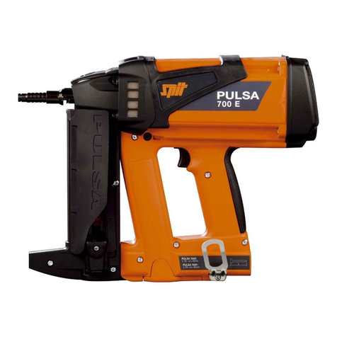
SPIT Spitfire P370 User manual

1
F
Consignes générales de sécurité
Seules peuvent être chargées de travaux avec un appareil de scellement des
personnes qualifiées ayant atteint l’âge de 18 ans. Ces personnes doivent connaître
parfaitement le fonctionnement de l’appareil et suivre exactement les instructions
du fabricant et les prescriptions de sécurité. Elles doivent être à même d’assurer
l’entretien de l’appareil.
Les charges et tampons utilisés doivent être exclusivement ceux prévus et
fabriqués par SPIT pour cet appareil.
L’appareil SPITFIRE P370 doit être vérifié avant l’emploi, afin de s’assurer du bon
fonctionnement des sécurités et de contrôler que la partie avant et le porte-munition
soient propres. S’assurer également du bon coulissement général de la partie mobile.
L’appareil ne doit être chargé qu’avant son emploi. Si l’appareil n’est pas utilisé, il
doit être déchargé et remis dans son emballage d’origine. Il ne doit en aucun cas
être transporté chargé.
L’opérateur doit être placé, lors du tir, dans une position stable. L’appareil doit être
tenu perpendiculairement au matériau support.
Lorsqu’un incident de tir survient, il faut immédiatement décharger l’appareil en
prenant toutes les précautions nécessaires. Si plusieurs incidents se produisent, en
informer le constructeur.
L’outil SPITFIRE P370 et ses chargeurs ne doivent être transportés que dans leur
emballage d’origine.
Ne jamais diriger l’extrémité du canon de scellement vers une personne. Le canon
doit être constamment dirigé vers le bas.
Ne jamais manœuvrer le canon avec le plat de la main.
Le bon état de l’appareil, même non utilisé, doit être vérifié au moins une fois
par an par le constructeur.
Il est interdit aux personnes non désignées à cet effet de faire usage d’un appareil de
scellement.
Il est interdit d’apporter à l’appareil toute autre modification que celles prévues dans
ce manuel.
Il est interdit d’effectuer un scellement de tôle profilée sur ossature métallique avant
de s’être assuré qu’il n’y a personne derrière.
On ne doit pas tenter une fixation en un point où le fer support de tôle profilée a été
endommagé ou présente un défaut. La fixation doit être effectuée à 2 cm au moins
de cet endroit.
Il est interdit de tenter une fixation sur des matériaux ne présentant pas de rigidité
suffisante ou insuffisamment résistants : brique creuse, carreau de plâtre, ardoise, etc.
Il est interdit d’enfoncer des tampons dans les matériaux cassants et durs, comme la
fonte, l’acier trempé, le marbre, le granit.
Il est interdit de réaliser des fixations sur béton à moins de 10 cm des arêtes.
Il est interdit d’utiliser un appareil de scellement dans des ateliers ou autres lieux où
existent des risques d’explosions.
Pendant l’utilisation de l’appareil, l’utilisateur et son entourage doivent porter des
lunettes de protection appropriées, un casque dur et un casque anti-bruit.
Notice 001_F.indd 26/02/04, 7:461

2
Généralités
L’outil SPITFIRE P370 est un appareil de scellement
de Haute Technologie.
• Remontée automatique de la masselotte
• Alimentation automatique des tampons
• Alimentation automatique des charges
Il est destiné à la fixation sur béton et acier.
C’est un appareil à tir indirect, de la classe A symbole A*,
conforme aux normes françaises NFE 71-100 et 71-101.
Le SPITFIRE P370 nécessite deux conditions pour obtenir la
percussion :
• Être maintenu fermement en appui contre le support.
• Actionner la détente.
Les instructions d’utilisations détaillées sont présentées dans les
pages suivantes de cette notice. Il est indispensable d’en prendre
connaissance avant d’utiliser votre SPITFIRE P370.
Cet appareil est homologué par le Banc
d’Epreuve de St-Etienne sous le n° 001137
Notice 001_F.indd 26/02/04, 7:462

3
F
Caractéristiques techniques
SPITFIRE P370
Catégorie.................................................... Tir indirect - classe A
Symbole A*
Norme NFE 71100-71101
Homologation ....................................................... CIP n° 001137
Longueur sans magasin ..................................................440 mm
Longueur avec magasin ..................................................455 mm
Poids sans magasin ...........................................................2,7 kg
Poids avec magasin .......................................................2,875 kg
Remontée automatique de masselotte
Réglage de puissance avec indicateur
Capacité magasin......................................................10 tampons
Possibilité d’indexage du magasin 4 positions
CHARGES
Conformité aux Normes Françaises......NFE 71-100 et E 71-101
et aux prescriptions C. I. P.
Calibre ..............................................................................6,3 / 10
Puissance
Marron ..........................................................................très faible
Vert ......................................................................................faible
Jaune.............................................................................moyenne
Rouge................................................................................... forte
Disque de charge de 10 unités
Boîte de 10 disques
TAMPONS
Tampons sans bande ....................................boîte de 100 unités
Tampons avec bande ....................................boîte de 500 unités
+ 1 ressort caoutchouc
Notice 001_F.indd 26/02/04, 7:463

4
Mise en œuvre
Mise en place du disque
chargeur
Déverrouiller le couvercle (cf. fig. 1).
Introduire le disque correctement dans son logement
Refermer le couvercle
introduction du tampon
(sans magasin)
Introduire le tampon dans le guide tampon jusqu’à son maintien
par le guidage plastique (cf. fig. 2).
Ne jamais se servir du plat de la main pour
repousser le tampon
Mise à feu Appliquer perpendiculairement l’appareil sur le matériau
(cf. fig. 5).
Maintenir l’appareil à deux mains en exerçant une pression vers
l’avant et actionner la détente.
Pion de présence
de tampons dans le
magasin
Lorsqu’un ou plusieurs tampons sont dans le magasin,
il est impossible d’introduire une nouvelle bande (cf. fig. 3).
Le pion en saillie atteste de la présence de tampons dans le
magasin
introduction d’une
bande de tampons
(avec magasin)
Déverrouiller le couvercle du magasin (cf. fig. 4).
Tirer vers l’arrière le couvercle magasin
Introduire la bande de tampons
Refermer le couvercle magasin (verrouillage automatique)
Notice 001_F.indd 26/02/04, 7:464

5
F
Mise en œuvre
Choix du tampon
applications standard Longueur
filetage tampon Désignation Code
Consommables
béton
Tampon tête de rivet C9 20 C 9-20 032740
25 C 9-25 032520
30 C 9-30 032530
35 C 9-35 032540
40 C 9-40 032550
50 C 9-50 032560
60 C 9-60 032570
70 C 9-70 032580
Avec pré-enfoncement 80 C 9-80 032590
90 C 9-90 032600
Tampon tête de rivet
rondelle Ø 14 CR9
25 CR 9-25 032070
30 CR 9-30 032100
40 CR 9-40 032090
50 CR 9-50 032010
60 CR 9-60 032020
70 CR 9-70 032030
Tampon en bande 20 C 9-20 011330
25 C 9-25 011331
30 C 9-30 011332
35 C 9-35 011333
40 C 9-40 011334
50 C 9-50 011335
60 C 9-60 011336
Nota : des accessoires avec tampons prémontés peuvent être utilisés (Etrésillons -
Posibanche - Clip A)
Consommables
acier
Tampon tête de rivet SC9 15 SC 9-15 032500
20 SC 9-20 032510
25 SC 9-25 032950
30 SC 9-30 032930
35 SC 9-35 032940
40 SC 9-40 032920
50 SC 9-50 032910
60 SC 9-60 032900
70 SC 9-70 032890
Tampon fileté SA9 Ø 6 x 100
6 21 SA 9-6 6/21 034820
10 25 SA 9-6 10/25 034850
15 30 SA 9-6 15/30 034900
Ø 7 x 150
6 21 SA 9-7 6/21 034000
10 25 SA 9-7 10/25 034050
15 30 SA 9-7 15/30 034070
en Ø 8, utiliser le SPIT P250
Tampon en bande 15 SC 9-15 011340
20 SC 9-20 011341
25 SC 9-25 011342
30 SC 9-30 011343
35 SC 9-35 011344
40 SC 9-40 011345
50 SC 9-50 011346
60 SC 9-60 011347
Notice 001_F.indd 26/02/04, 7:465

6
Contrôle des pièces d’usure
L’outil est équipé d’un ressort en caoutchouc (3) (pour le
retour de la masselotte), d’un ensemble bague d’isolation +
masselotte (2) (cf. fig. 8).
Ces pièces doivent être périodiquement vérifiées
Pièce d’usure Vérifier
Ressort (3) - longueur (mini 161 mm)
- Etat (coupures, usure…)
Bague d’isolation
+
masselotte (2)
- Epaisseur de la bague (mini 4 mm)
- Etat (coupures, usure…)
- Pas de partie ébréchée sur la
masselotte
Mise en œuvre
Choix de la charge
(cf. fig. 6)
- 031740 charge disque 6.3/10 marron - très faible
- 031600 charge disque 6.3/10 verte - faible
- 031700 charge disque 6.3/10 jaune - moyenne
- 011658 charge disque 6.3/10 rouge - forte
Conseils pratiques :
Le choix est fonction de :
• la nature et dureté du matériau support
• la longueur du tampon
• la nature de la pièce à fixer
Procéder par essais successifs en commençant par la puissance
la plus faible, puis l’augmenter si nécessaire.
Si la charge n’a pas fonctionné, attendre 20 secondes
en maintenant l’appareil sur la surface de travail, puis
relâcher la pression d’appui pour réarmer le système
de percussion et recommencer la mise à feu.
Déverrouiller le couvercle
Enlever le disque
L’appareil doit toujours être déchargé après
utilisation et avant rangement dans le coffret.
Les disques chargeurs partiellement utilisés
doivent être conservés pour une utilisation
ultérieure.
Retrait du disque
chargeur
Choix de la puissance
(cf. fig. 7)
Notice 001_F.indd 26/02/04, 7:476

7
F
Partie avant
Toujours décharger l’appareil :
- à la fin du travail
- avant tout changement de pièces (masselotte,
amortisseurs, etc.)
- avant tout nettoyage et entretien
Démontage Maintenir l’appareil vertical, en appui sur l’arrière (cf. fig. 9)
• Dévisser le nez de l’appareil (guide tampon ou magasin).
Si l’effort paraît trop important, utiliser une clé de 16.
Sortir la masselotte avec la bague et le ressort (cf. fig. 10)
Dévisser et sortir l’ensemble canon (pousser le canon vers le bas
et tourner (cf. fig. 11)
Nettoyage Utiliser les accessoires d’entretien contenus dans le coffret.
Un nettoyage de la partie avant de l’appareil, et en particulier
l’alésage intérieur du porte-canon, est nécessaire tous les 2000 tirs
ou chaque jour si l’appareil est utilisé en faible puissance.
Nettoyage de l’intérieur du canon
(écouvillon moyen)
l’extérieur avec la brosse.
Nettoyage de l’alésage poignée
(brosse + écouvillon)
Nettoyage masselotte
(brosser la tige)
• Vérifier l’état du ressort (longueur
mini 161 mm), éventuellement se
servir des repères sur le carter de la
poignée.
• Vérifier l’état de la bague d’isolation.
Pour le contrôle des pièces d’usure, se reporter au chapitre
précédent.
Notice 001_F.indd 26/02/04, 7:477

8
Partie avant
CONSEILS
L’énergie poudre nécessite un entretien
périodique pour éliminer la calamine déposée
par les fumées de combustion. Chaque fois que
la manipulation nécessite un effort anormal, ou
en cas de manque de puissance, percussion
de la charge sans enfoncement du tampon,
procéder au démontage de la partie avant
et nettoyer l’alésage du canon, la charge, la
masselotte.
Utiliser impérativement pour l’entretien le
lubrifiant SPIT. Nous conseillons d’essuyer les
pièces après huilage.
Nettoyage (suite)
Remontage Procéder en sens inverse du démontage
Positionner la rainure du canon en partie haute (cf. fig. 12)
Insérer l’ensemble canon dans la poignée et visser la bague
moletée
Après remontage, vérifier le bon coulissement du canon dans la
poignée
Introduire la bague d’isolation sur la tige de la masselotte
Introduire le ressort caoutchouc sur la tige
Positionner l’ensemble masselotte dans le canon
Visser le magasin (jusqu’au premier “clic” et faire un tour) ou le
guide tampon.
La détérioration de l’extrémité de la masselotte peut être la cause
d’un mauvaise fixation :
- mauvaise perpendicularité de la fixation
- cisaillement du tampon à la pénétration
• Vérifier l’usure ou la déformation éventuelle de la masselotte.
On peut rattraper par meulage les déformations de l’extrémité
jusqu’à concurrence de 3 mm en aménageant un chanfrein.
Maintenir la surface meulée perpendiculaire à l’axe de la
masselotte.
Notice 001_F.indd 26/02/04, 7:478

9
F
EFFETS CAUSES REMÈDES
Mauvais fonctionnement
du dispositif de
percussion ou
d’alimentation des
charges
- Effort insuffisant sur l’appareil
lors de la mise en appui
- Maintenir l’appareil en appui
- Le disque chargeur n’a pas
tourné
- Vérifier l’état de la barette
- Défaut de coulissement du
manchon porte-munition
- Démonter, nettoyer
- Mauvais fonctionnement du
disque chargeur
- Le vérifier
- Plus de tampon dans le magasin - Voir pion magasin
- Encrassement canon - Démonter, nettoyer
- Outil trop chaud - Laisser refroidir
Canon bloqué en arrière - Encrassement ensemble mobile
(canon)
- Démonter, nettoyer
- Outil trop chaud - Laisser refroidir
Manque ou variation de
puissance
- Détérioration de la masselotte - La changer
- Masselotte très érodée - La changer
- Détérioration du ressort - Le changer
- Détérioration de la bague
d’isolation
- La changer
Effort de mise en appui
trop important
- Encrassement du canon - Nettoyer, huiler et remonter
- Présence de corps étrangers - Nettoyer, huiler et remonter
Impossible de fermer le
couvercle du magasin
- Plus de 10 tampons dans le
magasin
- Enlever les tampons
- Mauvais coulissement du guide
tampon
- Contacter le S.A.V. SPIT
Blocage de la
masselotte
- Résidus de bande coincés - Nettoyer
Mauvaise alimentation
des tampons
- Présence de résidus dans le
magasin
- Nettoyer
- Mauvais coulissement du guide
tampon
- Contacter le S.A.V. SPIT
Incident de fonctionnement
PARTIE ARRIÈRE P370
Seul votre agent SPIT ou son représentant est
habilité à démonter cet ensemble.
Notice 001_F.indd 26/02/04, 7:479

10
General safety instructions
Only qualied persons over 18 years of age can be permitted to use a stud driver.
These persons must know perfectly how the tool works and must follow exactly the
manufacturer’s instructions and the safety regulations. They must be capable of
maintaining the tool.
The charges and studs used must be exclusively those designed and manufactured
by SPIT for this tool.
The SPITFIRE P370 must be checked before use, so as to ensure that the safety
devices are working properly and that the front end and the munition carrier are
clean. Also ensure that the moving part generally slides well.
The tool must be loaded just before use. If the tool is not in use, it must be unloaded
and put back into its original packing. It must not under any circumstances be
transported loaded.
When firing, the operator must be in a stable position. The tool must be held at right
angles to the base material.
When a firing incident occurs, the tool must be unloaded immediately, taking all
necessary precautions. If several incidents occur, inform the manufacturer.
The SPITFIRE P370 and its chargers must only be transported in their original
packing.
Never point the end of the stud driver at anyone. The driver must always be pointed
downwards.
Never operate the driver with the flat of the hand.
The manufacturer must check the condition of the tool, even if it is not used, at
least once a year.
It is prohibited for unauthorized persons to use a stud driver.
It is prohibited to make any modification to the tool other than those specified in this
manual.
It is prohibited to do stud driving on profiled sheet on a metal structure before having
ensured that there is no-one behind it.
Fixing must not be attempted at a point where the profiled sheet support iron has
been damaged or is defective. Fixing must be done at least 2 cm away from this
area.
It is prohibited to attempt fixing on materials which are not rigid or strong enough:
hollow brick, plasterboard, slate, etc.
It is prohibited to drive studs into brittle, hard materials, like cast iron, hardened steel,
marble or granite.
It is prohibited to do any fixing on concrete less than 10 cm from the edges.
It is prohibited to use a stud driver in workshops or other premises where there are
explosion risks.
When using the tool, the user and bystanders must wear suitable safety glasses, a
hard hat and hearing protection.
Notice 010_GB.indd 26/02/04, 7:5110

11
GB
General
The SPITFIRE P370 is a high-tech stud driver.
• Automatic rising of the inertia block
• Automatic feeding of studs
• Automatic feeding of charges
It is designed for fixing on concrete and steel.
It is an indirect firing tool, of class A symbol A*, complying with
French standards NFE 71-100 and 71-101.
The SPITFIRE P370 requires two conditions to obtain
percussion:
• To be held firmly resting against the support.
• To press the trigger.
Detailed instructions for use are presented in the following pages
of this manual. It is essential to familiarize yourself with them
before using your SPITFIRE P370.
This tool is approved by the St-Etienne
Testing Stand under n° 001137
Notice 010_GB.indd 26/02/04, 7:5111

12
Technical characteristics
SPITFIRE P370
Category....................................................Indirect firing - class A
Symbol A*
French standards: NFE 71100-71101
Approval ..............................................................CIP no. 001137
Length without magazine ............................................... 440 mm
Length with magazine .................................................... 455 mm
Weight without magazine ...................................................2.7 kg
Weight with magazine ....................................................2.875 kg
Automatic rising of the inertia block
Strength setting with indicator
Magazine capacity..........................................................10 studs
Possibility of indexing of magazine 4 positions
CHARGES
Compliance with French standards .......................... NFE 71-100
and E 71-101 and C. I. P. regulations
Calibre .............................................................................6.3 / 10
Strength
Brown ............................................................................ very light
Green ....................................................................................light
Yellow ..............................................................................medium
Red.....................................................................................heavy
10 unit charger disc
Box of 10 discs
STUDS
Studs without a strip ........................................... box of 100 units
Studs with a strip ................................................ box of 500 units
+ 1 rubber spring
Notice 010_GB.indd 26/02/04, 7:5112

13
GB
Using the tool
Fitting the charger disc Unlock the cover (see fig. 1).
Put the disc correctly into its housing
Close the cover
Inserting the stud
(without a magazine)
Insert the stud in the stud guide until it is held by the plastic guide
(see fig. 2).
Never use the flat of the hand to push
the stud back
Firing Apply the tool at right angles to the material (see fig. 5).
Hold the tool with both hands, exerting forward pressure, and
press the trigger. .
Pin indicating presence
of studs in the magazine
When one or more studs are in the magazine, it is impossible to
insert another strip (see fig. 3).
The projecting pin indicates the presence of studs in the
magazine
Inserting a strip of studs
(with a magazine)
Unlock the magazine’s cover (see fig. 4).
Pull the magazine cover back
Insert the strip of studs
Close the magazine cover (automatic locking)
Notice 010_GB.indd 26/02/04, 7:5113

14
Using the tool
Choosing the stud
Standard applications Length
thread stud Designation Code
Concrete
consumables
C9 rivet head stud 20 C 9-20 032740
25 C 9-25 032520
30 C 9-30 032530
35 C 9-35 032540
40 C 9-40 032550
50 C 9-50 032560
60 C 9-60 032570
70 C 9-70 032580
With pre-drinving 80 C 9-80 032590
90 C 9-90 032600
Rivet head stud
CR9 Ø 14 washer
25 CR 9-25 032070
30 CR 9-30 032100
40 CR 9-40 032090
50 CR 9-50 032010
60 CR 9-60 032020
70 CR 9-70 032030
Strip stud 20 C 9-20 011330
25 C 9-25 011331
30 C 9-30 011332
35 C 9-35 011333
40 C 9-40 011334
50 C 9-50 011335
60 C 9-60 011336
Nota : accessories with pre-fitted studs can be used (Studs -
Posibanche - A Clip)
Steel
consumables
SC9 rivet head stud 15 SC 9-15 032500
20 SC 9-20 032510
25 SC 9-25 032950
30 SC 9-30 032930
35 SC 9-35 032940
40 SC 9-40 032920
50 SC 9-50 032910
60 SC 9-60 032900
70 SC 9-70 032890
SA9 rivet head stud Ø 6 x 100
6 21 SA 9-6 6/21 034820
10 25 SA 9-6 10/25 034850
15 30 SA 9-6 15/30 034900
Ø 7 x 150
6 21 SA 9-7 6/21 034000
10 25 SA 9-7 10/25 034050
15 30 SA 9-7 15/30 034070
for Ø 8, use the SPIT P250
Strip stud 15 SC 9-15 011340
20 SC 9-20 011341
25 SC 9-25 011342
30 SC 9-30 011343
35 SC 9-35 011344
40 SC 9-40 011345
50 SC 9-50 011346
60 SC 9-60 011347
Notice 010_GB.indd 26/02/04, 7:5114

15
GB
Checking the wear parts
The tool is equipped with a rubber spring (3) (for the return of
the inertia block), an inertia block + insulation ring assembly (2)
(see fig. 8).
These parts must be checked at regular intervals
Wear part Check
Spring (3) - length (min. 161 mm)
- Condition (cuts, wear, etc.)
Insulation ring
+
inertia block (2)
- Thickness (mini 4 mm)
- Condition (cuts, wear, etc.)
- No chipped part on the inertia block
Using the tool
Choosing the charge
(see fig. 6)
- 031740 brown 6.3/10 disc charge - very light
- 031600 green 6.3/10 disc charge - light
- 031700 yellow 6.3/10 disc charge - medium
- 011658 red 6.3/10 disc charge - heavy
Tips :
Choose according to :
• the nature and hardness of the support material
• the length of the stud
• the nature of the part to be fixed
Proceed by successive trials, beginning with the lightest strength,
then increase if necessary.
If the charge has misfired, wait for 20 seconds,
keeping the tool on the work surface, then stop
pressing in order to reset the percussion system and
to resume firing.
Unlock the cover
Remove the disc
The tool must always be emptied after use and
before storage in the box. Partially used charger
discs must be kept for later use.
Removing the charger
disc
Choosing the strength
(see fig. 7)
Notice 010_GB.indd 26/02/04, 7:5215

16
Front part
Always unload the tool:
- on completion of work,
- before changing any parts (inertia block,
dampers, etc.)
- before doing any cleaning or maintenance
Disassembly Hold the tool vertical, resting on the back (see fig. 9)
• Unscrew the tool’s nose (stud guide or magazine).
If the effort seems too great, use a 16 mm spanner.
Take out the inertia block with the ring and the spring (see fig. 10)
Unscrew and take out the barrel assembly (push the barrel
downwards and turn (see fig. 11)
Cleaning Use the cleaning accessories contained in the box.
Cleaning the front part of the tool and in particular the inside bore of
the barrel holder is necessary every 2000 firings or each day if the
tool is used in light strength.
Cleaning of the inside of the barrel
(medium sponge), of the outside with
the brush.
Cleaning of the handle bore
(brush + sponge)
Cleaning of inertia block
(brush the rod)
• Check the condition of the spring
(min. length 161 mm). If necessary,
use the marks on the handle’s casing.
• Check the condition of the insulation
ring.
To check the wear parts, refer to the previous chapter.
Notice 010_GB.indd 26/02/04, 7:5216

17
GB
Front part
TIPS
Powder-actuated tools require regular
maintenance to remove the carbon deposited
by combustion fumes. Whenever the tool
requires unusual force, or when there is a lack
of strength or percussion of the charge without
driving in the stud, dismantle the front part and
clean the bore of the barrel, the charge and the
inertia block.
It is essential to use SPIT lubricant for
maintenance. We recommend wiping parts after
oiling them.
Cleaning (continued)
Reassembly Reassembly is the reverse of disassembly
Position the barrel’s groove at the top (see fig. 12)
Insert the barrel assembly in the handle and screw the knurled
ring
After reassembly, check that the barrel slides properly in the
handle
Insert the insulation ring on the inertia block’s rod
Insert the rubber ring on the rod
Position the inertia block assembly in the barrel
Screw up the magazine (until the first “click” and turn once) or the
stud guide.
Damage to the end of the inertia block can be the cause of poor
fixing:
- fixing not at right angles
- shearing of the stud on penetration
• Check the wear or possible deformation of the inertia block.
Deformation of the end can be trued up by grinding up to 3 mm
by making a chamfer.
Keep the ground surface at right angles to the centre line of the
inertia block.
Notice 010_GB.indd 26/02/04, 7:5217

18
EFFECTS CAUSES REMEDIES
Malfunctioning of
the charge feed or
percussion device
- Insufficient force on the tool
when resting it on the support
- Hold the tool resting on the support
- The charger disc has not turned - Check the condition of the small bar
- Munition carrier sleeve not sliding
properly
- Disassemble, clean
- Malfunctioning of the charger
disc
- Check it
- No more studs in the magazine - See magazine pin
- Barrel dirty - Disassemble, clean
- Tool too hot - Allow to cool
Barrel jammed at the
back
- Moving assembly (barrel) dirty) - Disassemble, clean
- Tool too hot - Allow to cool
Lack of power or
uctuation in power
- Deterioration of the inertia block - Change it
- Inertia block very eroded - Change it
- Deterioration of the spring - Change it
- Deterioration of the insulation
ring
- Change it
Too much force needed
to rest the tool on the
support
- Barrel dirty - Clean, oil and reassemble
- Presence of foreign matter - Clean, oil and reassemble
Impossible to close the
magazine’s cover
- More than 10 studs in the
magazine
- Remove the studs
- Stud guide not sliding properly - Contact SPIT’s after-sales service
department
Jamming of the inertia
block
- Strip residues stuck - Clean
Poor stud feed - Presence of residues in the
magazine
- Clean
- Stud guide not sliding properly - Contact SPIT’s after-sales service
department
Troubleshooting
P370 BACK PART
Only your SPIT agent or his representative is
authorized to disassemble this assembly.
Notice 010_GB.indd 26/02/04, 7:5218

19
I
Instruzioni generali di sicurezza
Possono venir incaricate di lavori con un apparechio per la sigillatura delle persone qualificate
aventi una età superiore ai 18 anni. Tali persone devono conoscere perfettamente il funzionamento
dell’apparecchio e seguire esattamente le istruzioni del fabbricante e le prescrizioni di sicurezza. Dette
persone devono essere in grado di assicurare la manutenzione dell’apparecchio.
Le cariche e i tamponi utilizzati devono essere esclusivamente quelli previsti e fabbricati dalla SPIT per
questo apparecchio.
L’apparecchio SPITFIRE P370 deve essere verificato prima di venir utilizzato, in modo da accertarsi
del buon funzionamento delle sicurezze e da controllare che la parte anteriore e il portamunizioni siano
puliti. Accertarsi altresì del buon scorrimento generale della parte mobile.
L’apparecchio deve essere caricato solamente prima di venir utilizzato. Se l’apparecchio non viene
utilizzato, deve essere scaricato e rimesso nel proprio imballaggio di origine. Non deve in alcun caso
essere trasportato caricato.
L’operatore deve essere posto, all’atto del tiro, in una posizione stabile. L’apparecchio deve essere
tenuto perpendicolarmente al materiale supporto.
Qualora succeda un incidente di tiro, occorre immediatamente scaricare l’apparecchio prendendo ogni
e qualsiasi precauzione necessaria. Se si verificano più incidenti, informarne il costruttore.
L’utensile SPITFIRE P370 ed i relativi caricatori devono essere trasportati solamente nel relativo
imballaggio di origine.
Non dirigere mai l’estremità della canna di sigillatura verso una persona. La canna deve essere
costantemente diretto verso il basso.
Non manovrare mai la canna con il palmo della mano.
Il buono stato dell’apparecchio, anche se non viene utilizzato, deve essere verificato al meno
una volta all’anno dal costruttore.
É vietato alle persone non appositamente designate far uso di un apparecchio per la sigillatura.
É vietato apportare all’apparecchio qualsiasi modifica diversa da quelle previste nel presente manuale.
É vietato effettuare la sigillatura di lamiera profilata su ossatura metallica prima di essersi accertati che
non ci sia nessuno dietro.
Non si deve tentare alcun fissaggio in un punto in cui il ferro supporto di lamiera profilata sia stato
danneggiato o presenti un difetto. Il fissaggio deve essere effettuato ad al meno 2 cm da tale punto.
É vietato tentare un fissaggio su dei materiali che non presentino una rigidità sufficiente o che non siano
sufficientemente resistenti: mattone cavo, piastrella di gesso, ardesia, ecc.
É vietato piantare tamponi in materiali rompenti e duri, come la ghisa, l’acciaio temprato, il marmo, il
granito.
É vietato realizzare fissaggi su calcestruzzo a meno di 10 cm dagli spigoli.
É vietato utilizzare un apparecchio per la sigillatura in officine od altri luoghi in cui ci siano dei rischi di
esplosioni.
Durante l’utilizzo dell’apparecchio, l’utente e quanti gli stiano intorno devono portare appropriati occhiali
di protezione, un casco rigido ed un casco antirumore.
Notice 019_I.indd 26/02/04, 7:5619

20
Generalità
L’utensile SPITFIRE P370 è un apparecchio per la sigillatura di
Alta Tecnologia.
•
Risalita automatica della massa battente del congegno d’innesco
• Alimentazione automatica dei tamponi
• Alimentazione automatica delle cariche
É destinato al fissaggio su calcestruzzo ed acciaio.
Si tratta di un apparecchio a tiro indiretto, della classe A simbolo
A*, conforme alle norme francesi NFE 71-100 e 71-101.
Lo SPITFIRE P370 necessita di due condizioni per ottenere la
percussione:
• Essere fermamente mantenuto in appoggio contro il supporto.
• Azionare il grilletto.
Le istruzioni per l’uso dettagliate vengono presentate nelle
pagine successive di queste avvertenze. É indispensable
conoscerle per bene prima di utilizzare lo SPITFIRE P370.
Questo apparecchio è omologato dal Banco
di Prova di Saint-Etienne (Dipartimento della
Loira – Francia) con il n° 001137
Notice 019_I.indd 26/02/04, 7:5620
Table of contents
Languages:
Other SPIT Nail Gun manuals
Popular Nail Gun manuals by other brands
Metabo HPT
Metabo HPT NR 3675DD Instruction and safety manual
EXTOL PREMIUM
EXTOL PREMIUM 8894580 Translation of the original user manual
DeWalt
DeWalt XR Li-Ion DCN680D2 Original instructions
Performance Tool
Performance Tool M643 owner's manual
Hitachi
Hitachi VH650 - Fencing Nailer, Full Head instruction manual

Parkside
Parkside PET 25 B1 Operation and safety notes
