Passeq Analog Code® Plug-in 9
Overview Operation
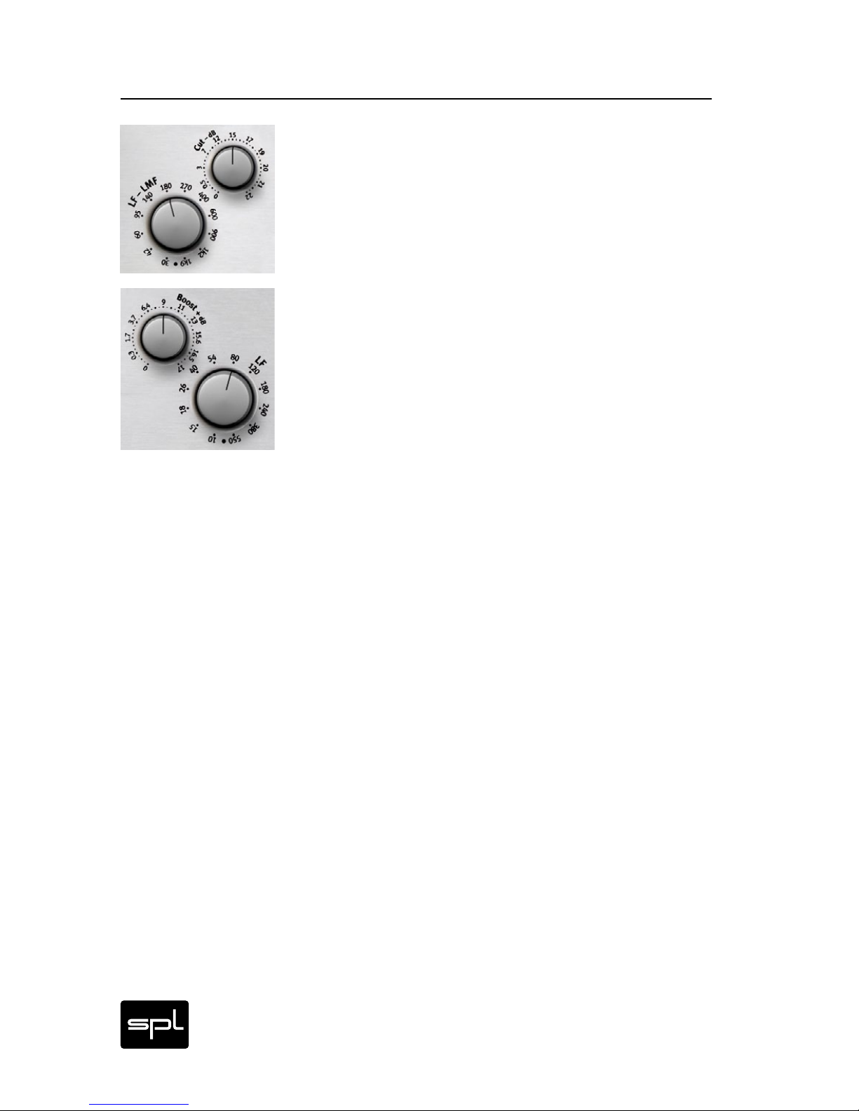
Allocation of Frequencies
One of the greatest Passeq design challenges was in determin-
ing the choice of frequencies, which in contrast to parametric EQ
designs, are fixed or nonadjustable. One could accept standard-
ized values from such as the so-called ISO frequencies, but such
measurements stem too much either from conventional measure-
ment standards or those from room corrections rather than choices
of what may be musically more sensible. In assigning the Passeq‘s
frequencies it was inevitable that we would rely on the nearly 30
years of experience of SPL’s chief developer, audio engineer and
musician, Wolfgang Neumann.
To enhance further our achieving this musical objective many audio
experts and musicians were consulted regarding their favored fre-
quencies. Among the many, David Reitzas, Michael Wagener, Bob
Ludwig, Ronald Prent and Peter Schmidt offered valuable advice.
From this point of departure we managed to determine that there
is definite agreement among professionals about their preferred
musical frequencies, and these differ clearly from the standard ISO
choices.
The results also showed that the closely meshed boost and cut fre-
quencies are important and sensible. Through them one can on the
one hand focus more precisely on a certain frequency, and on the
other, offer the option of influencing the Q factor (which is typically
rather small in passive designs) by creating so-called S curves. An
Example: Assume you wish to boost in the mids around 320 Hz, an
instrument or voice level while at the same time avoiding a boost
to the frequency range below it due to the small Q factor (high
bandwidth) of the filter, and perhaps even lower it. In this case,
let’s say you choose the LMF-MHF boost band and increase the
chosen (320 Hz) frequency range by about 3 dB. At the same time,
you chose a 4 dB reduction in the LF-LMF cut band. The close prox-
imity of the chosen frequencies allows you achieve an increase in
the slope between the two. This is “S slope EQ-ing” at its best, and
in this discipline, the Passeq is a world champion in both options
and results.