Splicecom S8000/718 Instruction Manual

Installation & Maintenance Manual
Version 4
June 2015

maximiser Installation and Maintenance Manual
Document No. 001
Version No. v4/0615/10
© Copyright SpliceCom Ltd
SpliceCom Ltd
The Hall Business Centre, Berry Lane
Chorleywood, Herts WD3 5EX
Tel: 01923 287700
Website: www.splicecom.com

Installation and Maintenance Manual
Contents
Installation and Maintenance Manual v4/0615/10 i
Contents
Introduction ......................................................................................................................................................... 1
Installing a System............................................................................................................................................... 2
Installing a S8000/S716 Call Server ................................................................................................................. 2
Installing a 5100/5108 Call Server .................................................................................................................. 3
System Configuration ......................................................................................................................................... 7
Manager .......................................................................................................................................................... 7
Configuring System Details ............................................................................................................................ 9
Configuring a Call Server .............................................................................................................................. 10
System Time .................................................................................................................................................. 13
Setting up Administrative Access ................................................................................................................. 14
Licencing ....................................................................................................................................................... 20
Connecting a Module .................................................................................................................................. 29
Connecting an Analogue Phone ................................................................................................................. 48
Connecting a PCS IP Phone ......................................................................................................................... 51
Installing User Software ............................................................................................................................... 62
Installing the SSL Gateway Application ........................................................................................................ 80
Connecting Multiple Call Servers ................................................................................................................. 83
Configuring system functionality ..................................................................................................................... 89
Configuring an Analogue Extension Port .................................................................................................... 89
Configuring an IP Phone .............................................................................................................................. 91
Working with Users ...................................................................................................................................... 94
Working with Dial Plans .............................................................................................................................. 130
Working with Groups .................................................................................................................................. 138
Routing calls via a Department .................................................................................................................. 146
Setting up the Contacts Database ............................................................................................................. 161
Using a Time Plan ....................................................................................................................................... 169
Conferencing .............................................................................................................................................. 173
Working with Companies ........................................................................................................................... 177
Working with Trunks ................................................................................................................................... 182
Working with DDI Plans .............................................................................................................................. 195
Working with LCR Plans .............................................................................................................................. 200
Using Area Codes ....................................................................................................................................... 202
Configuring Music Channels...................................................................................................................... 203
Using Events ............................................................................................................................................... 207
Using the TAPI Driver .................................................................................................................................. 209
Working with Voicemail .................................................................................................................................. 210
Voicemail Licensing .................................................................................................................................... 211
Voicemail Ports ........................................................................................................................................... 212
Voicemail for a User ................................................................................................................................... 216
Voicemail for a Department ....................................................................................................................... 233
Creating an Auto Attendant ....................................................................................................................... 246
Creating VXML Scripts ................................................................................................................................. 249
Call Recording ............................................................................................................................................. 256
Maintaining and Troubleshooting Voicemail ............................................................................................ 261
Internal Web Server......................................................................................................................................... 264
Data Routing ................................................................................................................................................... 267
Creating a WAN Link ................................................................................................................................... 267
Setting up IP Routes ................................................................................................................................... 268

Installation and Maintenance Manual
Contents
ii Installation and Maintenance Manual v4/0615/10
Setting up PPP ............................................................................................................................................. 268
Setting up Bandwidth on Demand (BOD) ................................................................................................ 269
Maintenance & Troubleshooting ................................................................................................................... 270
Manager Assist ........................................................................................................................................... 270
System Access ............................................................................................................................................. 272
Importing and Exporting the Configuration .............................................................................................. 273
Reset Switch ................................................................................................................................................ 281
Powering down a Call Server ..................................................................................................................... 282
Rebooting a module .................................................................................................................................. 283
Backing up the Database ........................................................................................................................... 283
Upgrading the System ................................................................................................................................ 286
Initial Configuration Boot Menu ................................................................................................................ 297
Accessing the log files ................................................................................................................................ 298
Using Setnet ............................................................................................................................................... 299
Using Telnet ................................................................................................................................................ 300
Field Descriptions ............................................................................................................................................ 302
Manage Company ...................................................................................................................................... 302
Users ........................................................................................................................................................... 302
Departments ............................................................................................................................................... 313
Groups ......................................................................................................................................................... 320
Time Plans ................................................................................................................................................... 321
Contacts ...................................................................................................................................................... 322
Meet Me Conference ................................................................................................................................. 324
Dial Plans ..................................................................................................................................................... 325
Companies .................................................................................................................................................. 331
Trunks .......................................................................................................................................................... 332
Trunk Groups .............................................................................................................................................. 336
DDI Plans ..................................................................................................................................................... 337
LCR Plans ..................................................................................................................................................... 337
Voicemail Ports ........................................................................................................................................... 338
Music Channels .......................................................................................................................................... 340
Events .......................................................................................................................................................... 341
VXML Scripts ................................................................................................................................................ 341
Auto Attendant ........................................................................................................................................... 343
Modules ...................................................................................................................................................... 343
Phones ........................................................................................................................................................ 350
Unassigned Phones ................................................................................................................................... 353
Unassigned Modules ................................................................................................................................. 354
System ......................................................................................................................................................... 354
Licences ...................................................................................................................................................... 355
Administrators ............................................................................................................................................. 355
Utilities ........................................................................................................................................................ 356
Area Codes .................................................................................................................................................. 357
WAN Links ................................................................................................................................................... 357
Index ................................................................................................................................................................ 361

Installation and Maintenance Manual
Introduction
Installation and Maintenance Manual v4/0615/10 1
Introduction
The purpose of this manual is to give a step by step guide on how to install, configure, maintain and
troubleshoot a maximiser system. This manual should be used in conjunction with the maximiser
Technical Reference manual which provides a feature guide of each element of a system together with
an understanding of the architecture used and in-depth technical data.
Please note that where the phrase “Call Server” is used this refers to the S8000, S716, 5100 Call Server,
5108 Call Server, 4100 Call Server and the 4140 Remote Call Server unless specified.

Installation and Maintenance Manual
Installing a System
2 Installation and Maintenance Manual v4/0615/10
Installing a System
This section of the manual describes how to set up a S8000/718 and 5100/5108 Call Server where one of
these will be the first unit to be installed on the customer site. Subsequent modules should then be
connected to this Call Server as described in the Connecting a Module from page 29. Where more than
one Call Server will be operational on a site these additional call servers should also be connected after
the initial S8000/718/5100/5108 has been set up, as described in the Connecting Multiple Call Servers
section from page 83.
Installing a S8000/S716 Call Server
Initial consideration
S8000 must be in installed on PC running OpenSUSE 12.3
Minimum hardware requirements:
S8004 to S8050 – 1 Gbps processor, 2 GB memory
S8100 and above – 3 Gbps Dual core processor, 8 GB memory
S8000 software is 32 bit so will run on 32 or 64 bit Linux (64 bit is recommended if a choice is
available)
Can reside on the same PC as SSL Gateway and Vision (except Vision Call Centre)
Linux configuration:
The IP address of the S8000 Call Server is the IP address of the Linux PC. This IP address must be
associated with eth0.
DHCP, IP routing, DNS, NFS Server and NTP services are all configured within Linux
The Linux PC must have a User called “splicecom”. It is recommended that Auto Login is turned
off for this User account.
Ensure that the Firewall available on the Linux PC is turned off
Enable Remote Administration (VNC)
Enable the sshd service
Ensure that Linux PC does not hibernate or shut down
Time must be obtained via NTP
The Linux Server must have an Internet connection
During the installation the Linux PC must be connected to the Internet or have access to the Linux
installation CD
If operating standalone for demonstration or training purposes Linux PC must be configured
with a Default Gateway IP address
The Linux Server must have an Internet connection to communicate with SpliceCom’s licence
authentication servers. The Heartbeat process will check every 30 days after initial 60 days trial
period. Terms and Conditions of “Heartbeat” accepted during installation. (Please refer to the
Installing the S8000/S716 licences section from page 27 for further details.)
When a standalone S8000 Call Server is installed it will become a Primary Call Server. All subsequent
Call Servers connected to this initial Call Server will become secondary call servers. Ensure that you
install the Call Server you wish to be the Primary first. If the Linux PC is connected to a network
during the installation and it detects that another Call Server exists on the network it will attempt to
join this system. Ensure the Linux PC is disconnected from the network during installation if this is
not required. (Please refer to Connecting Multiple Call Servers from page 83 for further details.)
Routine configuration via SSH for command line work or VNC for GUI work
Remote Management via Team Viewer or openvpn

Installation and Maintenance Manual
Installing a System
Installation and Maintenance Manual v4/0615/10 3
Installing the S8000 software
1It is recommended that the installation file, eg S8000-Linux.4.0.70.tar.gz, is placed in
/home/splicecom
2Open Terminal or ssh in.
3Go to \home\splicecom
4Extract the software into the folder /home/splicecom/S8000 by entering:
tar –xf filename
eg tar –xf S8000-Linux.4.0.70.tar.gz or tar –xf S8000- then press Tab
5Enter cd S8000 to go to this directory
6Enter ls and you will see the install script - install.SUSE
7The install script will also install the web server, ftp server and tftp software packages from the
Linux installation CD or from the Internet.
8Enter sudo ./install.SUSE
(use this command if you are using the Linux installation CD)
or
Enter sudo ./install.SUSE - net
(use this command if the installation files are to be retrieved via the Internet, preferred method)
9When requested for the password, enter the password for the root user on the Linux PC (if
splicecom is the only user on this PC then this will be the password to use).
10 Once the “Installation Complete” message appears and the prompt returns enter
11 sudo /sbin/reboot
Please note:
The maximiser root password will overwrite the system root password you may have set up earlier.
So be aware next time you ssh / telnet in.
The RTP port range of an S8000 is different from a 5100 call-server, this must be taken in account
when programming firewalls. Please make sure that ports 6900 to 7859 are open for use.
It has been found that in openSUSE 12.2 a change was made to way ftp works, if the S8000 is going
to be used with Vision then the following change MUST be made.
From the command line enter:-
cd /etc <enter>
Edit the vsftd.conf file and add the following line to bottom of the file:-
allow_writeable_chroot=yes
Save the change. And then enter the following command:-
/etc/init.d/vsftpd restart
Please now go to the System Configuration section from page 7 to start configuring the system.
Installing a 5100/5108 Call Server
Initial considerations
The Call Server will always have an IP address of 192.168.0.1 on initial boot up, until configured
otherwise. (Please refer to the Setting the IP Address of a 5100/5108 Call Server section from page
11 for further details.)
During power up the Call Server will search for a DHCP Server. If the Call Server is connected to the
network and it finds a DHCP Server its internal DHCP facility will be disabled, if it does not find a
DHCP server the internal DHCP server functionality will be enabled. If the Call Server is not
connected to the network, it will not find a DHCP server and the internal DHCP server functionality

Installation and Maintenance Manual
Installing a System
4 Installation and Maintenance Manual v4/0615/10
will be enabled. All this configuration can be re-configured afterwards however you may wish to
save yourself time by determining which of these scenarios you require before you boot up the Call
Server. (Please refer to the
Setting DHCP section from page 12 for further details.)
When a standalone 5100/5108 Call Server is powered up it will become a Primary Call Server. All
subsequent Call Servers connected to the initial Call Server will become secondary call servers.
Ensure that you install the Call Server you wish to be the Primary first. If a Call Server is connected to
a network during power up and it detects that another Call Server exists on the network it will
attempt to join this system. Ensure the Call Server is disconnected from the network during power
up if this is not required. (Please refer to Connecting Multiple Call Servers from page 83 for further
details.)
5100 Call Server – Front and Rear view
5108 Call Server – Front and Rear view

Installation and Maintenance Manual
Installing a System
Installation and Maintenance Manual v4/0615/10 5
Please note that the front view diagram is incorrect, the first LED is the LINK LED and the second is the
DISK drive LED.
4100 Call Server – Front and Rear view
4140 Remote Call Server – Front and Rear view

Installation and Maintenance Manual
Installing a System
6 Installation and Maintenance Manual v4/0615/10
Powering up the 5100/5108 Call Server
1Power up the Call Server by plugging in the power supply provided.
2On the 5100 and 5108 Call Servers the Disk Drive LED will flash to indicate a system check. (On the
4100 and 4140 Call Servers the NET LED will flash to indicate a system check.)
3The SpliceCom LED will become solid when the unit is ready.
Once the 5100/5108 Call Server has been powered up the following should be noted:
If the Call Server’s DHCP Server functionality has been enabled the Call Server will give out an
address range of 192.168.0.2 to 192.168.0.250, with 192.168.0.250 being the first address given out.
(For further information please refer to the
Setting DHCP section from page 12 for further details.)
When connecting to the LAN ports on the front of the 5100, 5108 or 4100 Call Server straight or
crossover cables can be used because each port automatically changes to MDI/MDX. (When
connecting to the LAN port at the back of the 4140 Remote Call Server a crossover cable is required.)
The ISDN Trunk ports available on a Call Server can be used to connect to the exchange or to
another system. Please refer to the Working with Trunks section from page 182 for further
information.
The system operates in native mode at G.711 64k with echo cancellation. If the maximiser system is
connected to the company LAN and that LAN is used to carry voice then that LAN must provide
Quality of Service via LAN switches.
The 5100 and 5108 Call Server and the 4140 Remote Call Server provide 16/4/8 analogue extension
ports respectively. When either of these Call Servers is the first to be installed each port will be
automatically assigned to a User named Extn2001, Extn2002 etc and given an extension numbers of
2001, 2002 etc. Please refer to the Connecting an Analogue Phone section from page 48 for further
information.
Please note that the first 8 analogue ports on the 5100 Call Server are activated, the remaining 8
ports will require a POTS licence to activate each port. Please refer to the Licenc section from page
20 for further information.
Please now go to the System Configuration section from page 7 to start configuring the system.

Installation and Maintenance Manual
System Configuration
Installation and Maintenance Manual v4/0615/10 7
System Configuration
Manager
The configuration of the maximiser system is controlled and stored on the LDAP database within the Call
Server. Manager is the application that is used to view and configure this database.
Changes to the configuration made via Manager or by a User via their handset are stored in the RAM and
copied regularly to the hard disk to be stored permanently. It is important to perform an orderly shut
down of the system before power down to ensure all changes are copied to the hard disk and so that the
hard disk is shut down cleanly - please refer to the Orderly Shut down of the File System section from
page 281 for further details.
Manager is a web based application which can be run from any Web browser (Internet Explorer v5 or
higher, or Apple Safari v3.2 or higher) that can connect to the maximiser system.
On initial installation/boot up of a Call Server full administrative access is available by logging in as
Manager
which has a password of
managerpassword
. For security, it is advisable to at least change the
password for this Administrator once access has been achieved. Please refer to the Setting Up
Administrative Access section from page 14 for further details.
Running Manager
1Your PC must have an IP connection to the Call Server.
2Via a web browser, open
http://
ip address of 5100/5108
/manager eg http://192.168.0.1/manager
or
http://
ip address of the Linux PC
/manager or http://localhost/manager
3Enter the Administrator name and password into the log in dialogue box. For the very first log in
after installation full access is available by logging in as follows:
User Name = Manager
Password = managerpassword
Working in Manager
On opening Manager a list of the configurable objects on the database is displayed in orange within the
navigation pane on the left hand side (please refer to the Manageable Objects section in the Technical
Reference manual for a description of each object). A single click on one of the objects will display a list
of the relevant entries in the database. The User’s list is displayed by default.

Installation and Maintenance Manual
System Configuration
8 Installation and Maintenance Manual v4/0615/10
The following options will assist you to navigate and configure the database:
Navigate within a list of entries
Display the first page of entries
Display the previous page of entries
Display the next page of entries
When a list of entries is displayed the Search box will be available at
the top of the navigation pane. Enter the specific entry you wish to
find in the Search box and then select Find or press Enter. The entry
required will appear at the top of the list. If the Search box is empty,
the Find button will take you to the top of the list.
Create a new entry. In most instances this will open a new configuration form for completion.
If you have created a new entry in error you must select the Delete button to remove it.
Cancel will only exit the configuration form and the new entry will be listed as
newDepartment, newTimePlan and so on.

Installation and Maintenance Manual
System Configuration
Installation and Maintenance Manual v4/0615/10 9
Configure an entry
To open, view and edit an entry click on the blue link
To save the changes and return to the previous screen
To save the changes and remain in the current entry.
To return to the previous screen. If changes have been made these will not be saved.
To delete the entry currently displayed. A confirmation message will be received.
To delete the current entry within the field
An entry may consist of more than one page and the names of these pages are
display at the top of the screen. Click on the page name to access that page. Use
the Apply button to save a change in one page before moving to another page.
When a field name is displayed in blue the entry for this field can be selected from
a list. Click on the field name and select the new entry required. The Cancel
button will return you to the previous screen. The Clear button will delete the
entry and leave the field empty.
If an entry for a field is orange, clicking on this link will display the configuration
form for this particular entry. The Cancel button will return you to the previous
screen.
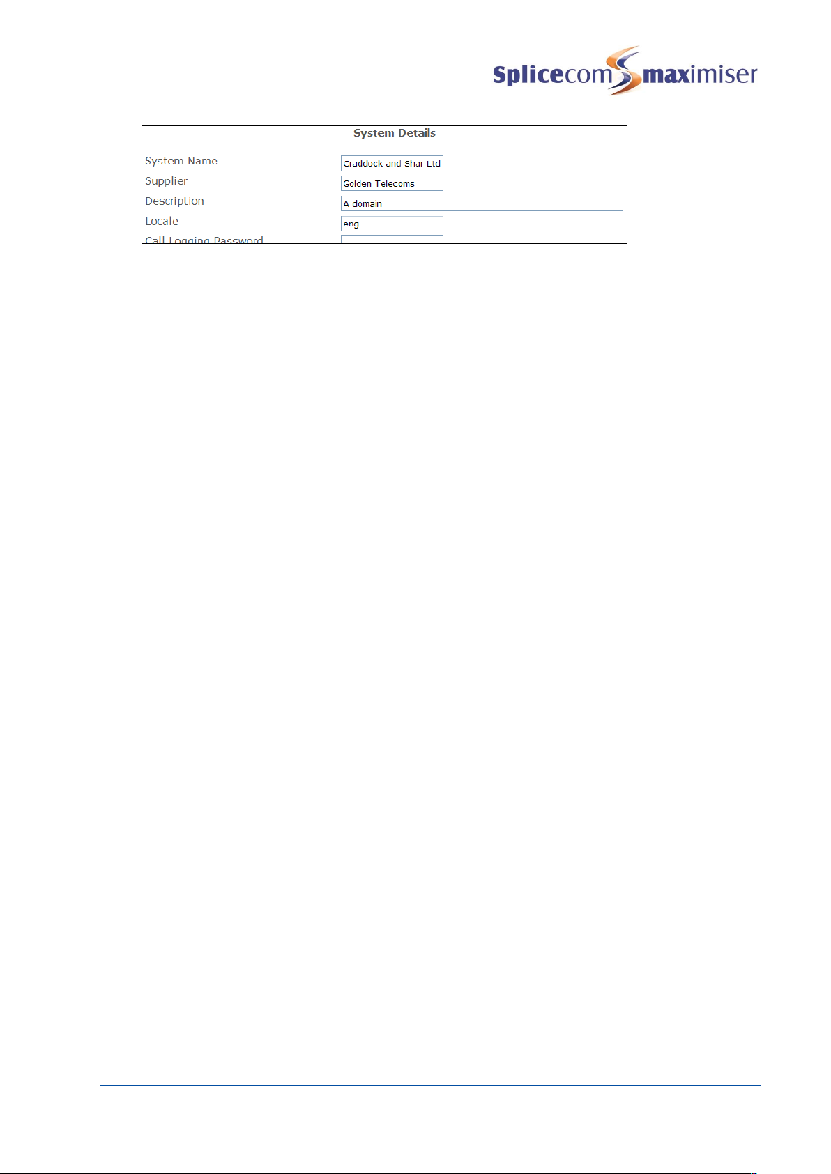
Configuring System Details
The System Details form of the configuration is used to enter information to identify the system such as
the customer’s name, the supplier’s name and any other text that will help to distinguish the system. If
licences have been purchased the text entered must match that provided with the licences. For further
information please refer to the Installing Licences section from page 20.
1In Manager, click on System
2The System Details form will be displayed.
3Enter a name for your system in the System Name field. Do not use punctuation in this field. This
field is useful to identify the system for troubleshooting purposes. If you have purchased licences
enter your given System Name. (This information will appear on the right hand side of the
Manager screen at the top and bottom once this entry has been updated.)
4The Supplier field is provided purely for information unless licences have been purchased. Enter
the Supplier Name provided with the licences. (This information will appear on the left hand side of
the Manager screen at the bottom once this entry has been updated.)
5The Description field is provided purely for information to help you identify the system. This
information will appear on the left hand side of the Manager screen at the top.
6The System Locale field will determine the language used for voicemail, ring sequences and Caller
Display.
7Select Update or Apply when ready.
Installation and Maintenance Manual
System Configuration
10 Installation and Maintenance Manual v4/0615/10
For information on the use of the Diagnostic Engineering Password, Web Password and Maintainer
Password please refer to the System Access section on page 272.
Call Logging
Call information to be used by third party call logging applications can be obtained from the system via
Telnet to port 4001. Please refer to the Call Logging Format document available via the SpliceCom
website>Reseller Area>Technical Resource>Manuals>SpliceCom APIs>Call Logging Output vx.x.x for
details on the description of each field.
Changing the Call Logging Password
The Call Logging Password is configurable within Manager and can be used to protect access to the call
logging data.
1In Manager select System
2In the Call Logging Password field enter the password required.
3Select Update or Apply when ready.
No logging output will occur without the Call Logging password being received (new line terminated).
The password must be transmitted in one block/packet.
Configuring a Call Server
A Call Server can be configured within Manager by selecting Modules and then the relevant Call Server.
The Module Details form for that Call Server will appear.
The Call Server’s Name can be changed to help identify the Call Server. The name must be unique,
should consist of alphanumerical characters only, not contain any punctuation and begin with a letter.
The Call Server must then be rebooted (please refer to page 283 for information on how to reboot a Call
Server).
The module’s hardware ID (Serial Number) is displayed together with its IP address and the current
version of software being run on this Call Server.

Installation and Maintenance Manual
System Configuration
Installation and Maintenance Manual v4/0615/10 11
The Flash LED button will instruct the Call Server’s SpliceCom LED to flash 20 times. This feature is useful
when multiple Call Servers are being used on a system and will identify the physical Call Server from its
configuration form. For information on working with multiple Call Servers please refer to page 83.
Please note: that for a S8000/S716 Call Server the IP address field cannot be changed and the IP Routes
tab will not be available as this information is taken from the Linux PC.
For further information on upgrading the software on a Call Server please refer to Upgrading a System
from page 286. For further information on using the Module Status field please refer to Connecting
Mulitple Call Servers on page 83.
Setting the IP Address of a 5100/5108 Call Server
By default, a 5100/5108 Call Server will have an IP address of 192.168.0.1. To change this address the
following configuration can be made:
1In Manager, select Modules
2From the Modules list select the Call Server required
3The Module Details form for that Call Server will be displayed.
4Within the IP Address field enter the IP Address to be used by the Call Server.
5Select Apply when ready.
6Select the Call Server page and within the DHCP Base Address field enter address for the network
the Call Server is to connect to (default = 192.168.0.0).
7Within the DHCP Base Mask field enter the subnet mask for the network that the Call Server is to
connect to (default = 255.255.255.0).
8Select Update or Apply when ready.
9Reboot the Call Server (please refer to page 283 for information on how to reboot a Call Server.)
Please note that if the Call Server has DHCP enabled (as described below) and this IP address is not on
the same network as the DHCP Start and End Address, DHCP will not be operational.

Installation and Maintenance Manual
System Configuration
12 Installation and Maintenance Manual v4/0615/10
A list of each module’s IP address
can be viewed in Manager by
opening Manager Assist and
selecting System Utilities and
then IP Addresses.
Setting DHCP on a 5100/5018 Call Server
During power up a 5100/5018 Call Server will search for a DHCP Server, if not found, its internal DHCP
server functionality will be enabled and will give out an address range of 192.168.0.1 to 192.168.0.250. If
the Call Server finds a DHCP Server the DHCP facility will be disabled.
To change this default configuration the following changes can be made.
1In Manager, select Modules
2From the Modules List select the required
Call Server.
3The Module Details form for that Call Server will
be displayed.
4At the top of the form select the Call Server
page. The Call Server Details form will appear.
5From the DHCP Server Mode list the following
options can be selected:
Enable - The Call Server will act as the DHCP
server using the IP Address range specified in
the DHCP Start Address and DHCP End Address
fields.
Please note: If another DHCP Server is detected
on the network and the Call Server is rebooted it
will continue to use 192.168.0.1 or it’s previously
configured IP Address and disable its own DHCP
Server which means it will no longer give out IP
addresses.
If the DHCP Server mode is re-enabled having
previously been disabled, the Call Server will
firstly check whether another DHCP Server exists
on the network. Only if it does not receive an IP address will it become a DHCP Server.
Disable – DHCP is disabled; the Call Server will use the IP address entered in the IP Address field
within the General page. (This is the recommended option if DHCP is being provided from another
vendor.)
Client – the Call Server will act as the DHCP client obtaining an IP address from a DHCP Server on
the network.

Installation and Maintenance Manual
System Configuration
Installation and Maintenance Manual v4/0615/10 13
6The DHCP Start Address and DHCP End Address fields specify the range of IP addresses to be given
out when the DHCP Server Mode is set to Enable. (Please note that these fields are irrelevant if the
DHCP Server Mode is set to Disabled.)
7The DHCP Base Address specifies the network on which the Call Server will be allocating IP
addresses (default = 192.168.0.0). If DHCP is disabled this must be configured to match the
network that the Call Server is on.
8The DHCP Base Mask specifies the subnet mask to be used by the Call Server and if the DHCP
Server Mode is set to Enable this is subnet mask given out. If DHCP is disabled this must be
configured to match the network that the Call Server is on.
9The DHCP Router field specifies the default gateway IP address to be used by the Call Server, and if
the DHCP Server mode is set to Enable this will be the Default Gateway address given out.
10 Select Update or Apply when ready.
11 Reboot the Call Server (please refer to page 283 for information on how to reboot a Call Server.)
Please note:
When using the default configuration, 192.168.0.250 will be the first IP address to be given out,
followed by 192.168.0.249 etc.
On initial connection a PCS 58x, 57x, 56x, 55x, 410, 400 and 100 will obtain its IP address from a DHCP
server.
On initial connection a Phone Module will obtain its IP address from a DHCP server.
If the DHCP Server Mode is set to Client and the Call Server is unable find a DHCP server on reboot
the SpliceCom LED will turn on for 5 seconds then off for 5 seconds continually until a DHCP server is
found.
Using Auto Add Phones
This feature determines whether phones (analogue or IP) will be able to automatically register with the
system. If turned on (default), each Phone Module and IP Phone will be able to automatically register on
the relevant Call Server, each port and phone will be listed in the configuration and a User automatically
created. If turned off, each Phone Module and IP Phone must be manually registered on the system.
Turn On/Off Auto Add Phones
1In Manager, select Modules
2Select the Call Server required
3Select the Call Server page.
4In the Auto Add Phones check box tick to turn on or untick to turn off this feature.
Please refer to the Connecting a Phone Module section from page 39 and the Connecting a PCS IP Phone
section from page 51 for further details.
System Time
The System configuration form displays the current date and time used by the system. This setting can be
changed as follows:
1In Manager Assist, select System Utilities then Set Time
2Enter the date and time required
3Select Update when ready.
4This information will be sent and updated on all handsets on the system

Installation and Maintenance Manual
System Configuration
14 Installation and Maintenance Manual v4/0615/10
Please note:
The system will take into account British Summer Time.
If multiply Call Servers are being used on one system the above time will be the time used by the
Call Server whose Manager is being viewed. Each Call Server can have a different date and time.
This information will be sent and updated on all handsets registered to the specific Call Server.
On a S8000/S716 the time must be obtained via an NTP server.
A Time Zone can be set when the time displayed in, for example, call logging information needs to be
identified with its Time Zone. This is useful when, for example, one maximiser system with multiple Call
Servers is working across multiple countries or states and the time of a call needs to be identified with its
correct Time Zone. (For further information on working with multiple Call Servers please refer to page
83.)
Each Call Server can have a different Time Zone and is configured as follows:
1Open Manager on the Call Server to be configured
2Within Manager Assist, select System Utilities and then Set Time
3From the Time Zone list box select the option required
4Select Update when ready.
5Reboot the Call Server (please refer to page 283 for further information)
Please note: Setnet can be used to set the time zone for a specific Phone Module. For further
information please refer to the Using Setnet section from page 299.
Setting up Administrative Access
Default Administrator
By default administration access to the database via Manager is available by logging in as “Manager”
using the password “managerpassword”. This Administrator has full access to the database. For security,
it is advisable to at least change the password for this Administrator once access has been achieved.
1In Manager, select Administrators
2The Administrator List will be displayed
3Select Manager
4In the Password field enter the password required. Alpha-numeric characters only.
5Select Update or Apply when ready
Please note: This default Administrator, Manager, gives Authorised Access to new Administrators as
described below. It is therefore recommended that Manager is not deleted.

Installation and Maintenance Manual
System Configuration
Installation and Maintenance Manual v4/0615/10 15
Additional Administrators
Additional administrators can also be created to enable staff to log on to Manager but have limited
access to the configuration. A new administrator can be created as follows.
Creating a new Administrator via the wizard
1In Manager, open Manager Assist and select System Wizards
2Select System Administrators
3Enter a Name, Description and Password for the new administrator.
4Ensure Show Enabled Values is ticked (this will enable you to select the sections of the
configuration this administrator can have access to, otherwise all pages will be visible and editable
dependent on the rights given).
5If the Companies feature is being used on this system select the company that this administrator
can have access to (otherwise the administrator will have access to all Users, Departments etc). For
further information on the Companies feature please refer to page 177.
6From the Default Page list select the page that will be displayed when Manager is first opened by
this Administrator.
7Select the Next Page button.
8From the Show: list box select one of the pages that this Administrator will need access to, eg
Users.
9From the Add/Delete list box select one of these options:
Yes – the Administrator will be able to add and delete entries within this page.
No – the Administrator will be able to amend existing entries, but the Add and Delete buttons
will not be available.
10 Click on the Add Row button, if more pages are required
11 Repeat steps 8-10 for all the pages that this Administrator need access to.

Installation and Maintenance Manual
System Configuration
16 Installation and Maintenance Manual v4/0615/10
12 Select the Next Page button.
13 From the Add Default Rights list box select either:
Yes – all rights will be given to each page listed below, however full access will be dependent
on whether Yes or No was selected within the previous page.
No – specify the rights required to each page in the Custom Admin Rights section, however full
access will be dependent on whether Yes or No was selected within the previous page.
14 Select the Next Page button.
15 An overview of the options selected will be displayed.
16 Select the Create Administrator button
17 The New Administrator Complete screen will display the new Administrator you have completed.
You will also see this new Administrator within the Administrators section of the configuration.
This manual suits for next models
4
Table of contents
Popular Server manuals by other brands

Brocade Communications Systems
Brocade Communications Systems FC4 Brocade 5000 Hardware reference manual

Bosanova
Bosanova LTC-1300 Specifications

Acnodes
Acnodes RMC 7182 user manual

Wegener
Wegener iPump 562 user manual

Wieland
Wieland WIENET SDS Series installation instructions

Fujitsu
Fujitsu PRIMERGY BX600 reference guide


Dell
Dell PowerEdge 1500SC Attachment guide

Sun Microsystems
Sun Microsystems Sun Fire X4150 Server Administration guide

NMS Communications
NMS Communications Vision VS 5000 Installing

ACTi
ACTi TVW-100 Quick installation guide

HP
HP T5530 - Compaq Thin Client Administrator's guide

Gigabyte
Gigabyte R123-C00-AA01 user manual