Sport Flyers WildFly 3D User manual

1
WILD FLY 3D EP BIPLANE SPECIFICATIONS:
●Wing Span: 27.5 Inches
●Wing Area: 330 Square Inches
●Length: 31.5 Inches
●Weight RTF: 12.5-13.75 Ounces
●Wing Loading: 5.5-6 Ounces/Square Foot
●Functions: Ailerons, Elevator, Rudder and Throttle
●Radio Required: 4 Channel or More w/3 Micro Servos and Micro Rx
Recommended Power System:
●370 with Gear Box or Brushless Direct Drive
●2 Cell 910mAH - 1250mAH LiPO Flight Battery
●14 Amp Micro ESC
ASSEMBLY INSTRUCTIONS
The Sport Flyers Wild Fly 3D EP Biplane
is sold exclusively in the USA by Hobby People
18480 Bandilier Circle, Fountain Valley, CA 92708
All contents copyright © 2005, Hobby People
Version V1.0 May 2005
Kit Product Number
160530 (Includes Motor and Gear Box)
160531 (Does Not Include Motor or Gear Box)
Love Foamies? Tired of ones that are a hassle to build, have a finish that is just not up to par, and when you're done, flex like a
wet noodle? We've got you covered with the new, simple, easy-to-assemble Wild Fly 3D EP. Because of the Wild Fly 3D EP's
factory-applied color scheme and interlocking parts, you'll be out to the field in no time. You'll just need some Zap-O C/A+ for
foam and foam-friendly kicker, and a few simple tools to get your Wild Fly 3D EP in the air.
Once you're at the field, get ready to hang on! Even with the stock 370 brushed motor, you'll see great performance. Get ready
to wring it out with all the maneuvers that only a lightweight aircraft can provide. Drop in a brushless motor and you'll see
INCREDIBLE hovering performance. If you're an experienced 3D pilot, the Wild Fly 3D EP takes you to the next step in
precision because of its 3-Dimensional fuselage shape. If you're just learning to hover, you've found the right bird. This one was
made to hover and you'll fly lower and better than ever before.

2
TABLE OF CONTENTS
This R/C airplane is not a toy! If misused or abused, it can cause serious bodily injury and/or damage to property. Fly only in open
areas and preferably at a dedicated R/C flying site. We suggest having a qualified instructor carefully inspect your airplane before
its first flight. Please carefully read and follow all instructions included with this airplane, your radio control system and any other
components purchased separately.
OUR GUARANTEE
Hobby People guarantees this kit to be free from defects in both material and workmanship at the date of purchase. This does not cover
any component parts damaged by use, misuse or modification. In no case shall Hobby People's liability exceed the original cost of the
purchased kit.
In that Hobby People has no control over the final assembly or material used for final assembly, no liability shall be assumed for any damage
resulting from the use by the user of the final user-assembled product. By the act of using the final user-assembled product, the user accepts all
resulting liability.
FOR YOUR INFORMATION
To make your modeling experience totally enjoyable, we recommend that you get experienced, knowledgeable help with assembly and during
your first flights. Your local hobby shop has information about flying clubs in your area whose membership includes qualified instructors. If there
is no hobby shop in your area, we recommend that you contact the AMA at the address below. They will be able to help you locate a flying field
near you.
Academy of Model Aeronautics
5151 East Memorial Drive
Muncie IN 47302-9252
(800) 435-9262
www.modelaircraft.org
SAFETY WARNING
Check out our website for more information on
this and other exciting Sport Flyers aircraft
http://www.hobbypeople.net
Safety Warning ...................................................................................... 2
Introduction ............................................................................................ 3
Customer Service Information .............................................................. 3
Section 1: Our Recommendations ....................................................... 4
Section 2: Lithium Polymer Battery Warnings - Please Read ............ 5
Section 3: Tools and Supplies Required ............................................. 6
Section 4: Kit Contents ........................................................................ 6
Section 5: A Warning About Working with Foam ................................. 7
Section 6: Fuselage Assembly ............................................................. 7
Section 7: Stabilizer Installation ......................................................... 10
Section 8: Top and Bottom Wing Installation .................................... 13
Section 9: Control Linkages Installation ........................................... 16
Section 10: Final Assembly ................................................................ 20
Section 11: Balance Point and Control Throws ................................ 22
Product Evaluation Sheet ................................................................... 23

3
Thank you for purchasing the Sport Flyers Wild Fly 3D EP Biplane. Before completing the final assembly of your new
airplane, please carefully read through this instruction manual in its entirety. Doing so will ensure your success the
first time around!
WILD FLY 3D EP BIPLANE FEATURES
●Factory-Cut and Printed Foam Parts
●Simple, Interlocking Assembly
●Full-Shape Fuselage for Stiffness. No Tail Flexing Problems
●Accepts a Wide Range of Power Systems and Radio Equipment
●Different Color Scheme on Top and Bottom Presents Well During Maneuvers
●Adjustable Firewall Makes Installation of Different Motors Simple and Easy
●Includes all Necessary Hardware
●Fast and Easy Assembly - Over 75 High-Resolution Digital Photos to Guide You
This instruction manual is designed to guide you through the entire assembly process of your new airplane in the least amount of
time possible. Along the way you'll learn how to properly assemble your new airplane and also learn tips that will help you in the
future. We have listed some of our recommendations below. Please read through them before beginning assembly.
●Please read through each step before beginning assembly.
You should find the layout very complete and straightforward.
Our goal is to guide you through assembly without any of the
headaches and hassles that you might expect.
●There are check boxes next to each procedure. After you
complete a procedure, check off the box. This will help prevent
you from losing your place.
●Cover your work table with brown paper or a soft cloth, both
to protect the table and to protect the parts.
●Keep a couple of small bowls or jars handy to put the small
parts in after you open the accessory bags.
●We're all excited to get a new airplane in the air, but take your
time. This will ensure you build a straight, strong and great
flying airplane.
●If you come across this symbol ☞, it means that this is an
important point or an assembly hint.
If you should find a part missing or damaged, or have any questions about assembly, please contact us at the address below:
To enable us to better serve your needs, please include your email address with any correspondence you send to us. Your email
address will be added to our Customer Service Database so you will automatically receive free updates and tech notices for your
particular product. You will also receive repair status updates (if applicable) and other important information about your product
as it becomes available.
IMPORTANT INFORMATION ABOUT YOUR EMAIL ADDRESS
INTRODUCTION
CHECK IT OUT! We urge you to come check out our website at http://globalservices.globalhobby.com. There you will find public message
boards frequented by other Sport Flyers product owners and the Sport Flyers support staff. This is a great place to learn about new products,
get help and suggestions for your product or just simply hang out and chat with people that share your same interests.
Hobby People will not disclose the information it collects to outside parties. Hobby People does not sell,
trade, or rent your personal information to others . Your privacy is important to us.
CUSTOMER SERVICE INFORMATION
Global Services
18480 Bandilier Circle
Fountain Valley, CA 92708
Phone: (714) 963-0329
Fax: (714) 964-6236
Email: service@globalhobby.net

4
This section describes our recommendations to help you in deciding which types of accessories to purchase for your new
Wild Fly 3D EP Biplane. Please read through this entire section very carefully. We have provided you with tips and
recommendations that, if followed, will result in a great flying airplane. Failure to follow our recommendations may
result in a poor flying airplane.
SECTION 1: OUR RECOMMENDATIONS
What Motor, Speed Control and Flight Battery Should I Use?
The Wild Fly 3D EP Biplane accepts a wide range of power systems. The stock power system (included with kit # 160530) features
a 370 motor with gear box. For this setup, we suggest using an 10x4.5 Slow-Flyer propeller, a 14 amp brushed ESC and a 2 cell
910mAH-1250mAH LiPO flight battery. This power system will provide spirited
performance and pull the airplane through basic aerobatics.
For all-out 3D-style flying, we suggest using a brushless
power system. A good combination would be an AXI
2208/34 brushless direct-drive motor with a 10x3.8 Slow-Flyer propeller, a 10 amp brushless ESC and a
2 cell 910mAH-1250mAH LiPO flight battery. WHEN CHOOSING YOUR OWN POWER SYSTEM, MAKE
SURE TO CHOOSE AN ESC THAT IS RATED FOR THE AMOUNT OF AMPERAGE YOUR MOTOR,
PROPELLER AND FLIGHT BATTERY WILL DRAW.
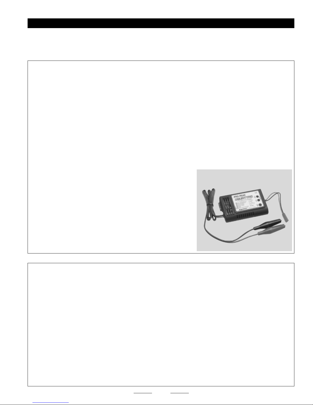
To charge your LiPO flight battery, you MUST use a LiPO-compatible charger. We suggest using the Pro-Peak LiPO charger.
What Radio, Receiver and Servos Should I Use?
You will need to use a 4 or more channel transmitter with a 4 or more channel
micro receiver. The receiver should be as light as possible, preferably 1/2oz.
or less. We suggest using the Cirrus MRX-4II Micro receiver.
The servos you use should be the lightest available, yet still have an adequate
amount of torque. We suggest using servos that weigh no more than 9-10
grams and have a torque rating of no less than 11 ounces per square inch.
Cirrus CS-09 servos or Hitec HS-55 servos would be a perfect choice.
✦✦
✦✦
✦IMPORTANT✦✦
✦✦
✦The MRX-4II receiver has a range of approximately 500 yards (~1/4 mile). Keep this in mind when flying the
airplane while using this receiver.
QTY. 1 Hitec Laser 4 FM Transmitter
QTY. 1 443534 Cirrus MRX-4II FM Micro Receiver
QTY. 1 444216 Cirrus Crystal for MRX-4II
QTY. 3 444045 Cirrus CS-09 Micro Servos
QTY. 2 444713 Cirrus 12" Servo Extensions
QTY. 1 131384 WattAge 10x4.5 Propeller
QTY. 1 866129 Dubro 1-1/2" Plastic Spinner
QTY. 1 158112 XTRA 14A Micro Electronic Speed Control
QTY. 1 128755 WattAge 2 Cell 1250mAH LiPO Flight Battery
QTY. 1 158370 Pro-Peak Quattro LiPO Charger
QTY. 1 869020 Dubro Double-Sided Tape
QTY. 1 568906 Dubro Hook & Loop Material (Velcro)
QTY. 1 Clear Vinyl Tape for Hinging
QTY. 1 Nylon Cable-Ties (Small)
Here's a List of What We Used to Finish Our Wild Fly 3D EP Biplane
✦✦
✦✦
✦IMPORTANT✦✦
✦✦
✦The part number for the Cirrus servos is compatible with all name-brand radio control systems. These servos use a universal
connector. The Cirrus receiver is compatible with all connector types and is auto-shift capable. The part number for the Cirrus servo extensions
is compatible with S/JR connectors.
QTY. 1 648586 AXI 2208/34 Direct Drive Brushless Motor
QTY. 1 701448 Castle Creations Phoenix 10 Brushless ESC
QTY. 1 608438 APC 10 x 3.8SF Propeller
QTY. 1 128755 WattAge 2 Cell 1250mAH LiPO Flight Battery
In addition to the items listed above, here's a list of the items we recommend for a brushless setup.
Use this setup for extreme power and 3D aerobatics and hovering capability.
5
SECTION 2: LITHIUM POLYMER BATTERY WARNINGS - PLEASE READ
Please read and understand the warnings listed in this section. Make sure to read any and all warnings
included in the packaging with your flight battery, too. If used improperly, lithium polymer batteries can be
very dangerous, so please follow these warnings and suggestions at all times.
WARNINGS AND SAFETY PRECAUTIONS FOR ALL BRANDS OF LITHIUM POLYMER BATTERIES
●This product may explode or catch fire. Serious injury can result from misuse. Serious injury, loss of property, fire and death
can result from misuse of this product.
●All instructions, warnings and cautions must be followed at all times. Failure to do so can lead to serious injury or fire.
●Do NOT use this product before reading and understanding all directions and warnings.
●Do NOT overcharge. Maximum voltage for each pack must be followed.
●Do NOT over-discharge. NEVER discharge below minimum volts.
●Do NOT discharge at a rate greater than the maximum continuous discharge.
●Do NOT use or charge if the battery is hot.
●ONLY use a charger made for Lithium Polymer batteries.
●Do NOT charge at a rate higher than 1C. Example: if the battery’s rating is 340mAH, then the charger’s charge rate must be set
at 340mAH or less.
●Do NOT leave in direct sunlight or in a hot car or storage area.
●Do NOT get wet or expose to moisture.
●Do NOT short-circuit the battery.
●ONLY discharge and charge the battery outdoors or in a firesafe container.
●Do NOT charge with reverse polarity.
●Do NOT leave the battery connected when not in use.
●Do NOT operate or charge unattended.
●Do NOT solder to the battery directly and do not get the battery hot in any way.
CHARGING PRECAUTIONS FOR ALL BRANDS OF LITHIUM POLYMER BATTERIES
●Do NOT use the product if you do not understand the warnings and proper use of the product.
●Always let the battery cool and "rest" between uses and charging.
●To avoid over-discharging, only use a speed control that is made for LiPO batteries.
●We recommend the use of a firesafe container when charging or storing.
●Do NOT charge inside your car or inside your house.
●Inspect the battery before each use for swelling or other malformation. If the cell has ballooned, it MUST be discarded.
●Set the charger to 1C (charge at 1/2C or less for the first 5 cycles).
●Check polarity and then connect battery to charger.
●In use, do not over-discharge or exceed maximum discharge.
●When handling the battery, remember not to poke, bend or damage the cell. The cell outer casing is soft and can be damaged.
●Remember, the cells must never exceed 160 degrees Fahrenheit for any reason.
You MUST use a LiPO-compatible
charger, like the Pro-Peak Quattro,
to charge LiPO batteries
P/N 158370

6
We have organized the parts as they come out of the box for easier identification during assembly. Before you begin assembly,
group the parts as we list them below. This will ensure that you have all of the parts before you begin assembly and it will also help
you become familiar with each part.
If you find any parts missing or damaged, please contact us as soon as possible, using the Customer Service
Information on page # 3. A complete replacement parts list can be found on page # 23.
SECTION 4: KIT CONTENTS
❑(A) Fuselage - 1
❑(B) Top Wing - 1
❑(C) Bottom Wing - 1
❑(D) Horizontal Stabilizer w/Elevator - 1
❑(E) Vertical Stabilizer w/Rudder - 1
❑(F) Wing Struts - 2
❑(G) Rear Fuselage Bottom - 1
❑(H) Front Fuselage Bottom - 1
❑(I) Inner Fuselage Supports - 3
❑(J) Landing Gear Wire - 1
❑(K) Assorted Reinforcement Board - 1
❑(L) Assorted Plywood Supports - 1
❑(M) Pushrod Wires - 6
❑(N) Plastic Parts Tree - 1
❑(O) Carbon Support Rods - 2
❑(P) Motor and Gear Box - 1
❑(Q) Motor Mounting Screws - 3
❑Pencil
❑Dubro T-Pins # 567677
❑Builder's Triangle
❑220 Grit Sandpaper w/Sanding Block
❑Paper Towels
❑K&S 30 Watt Soldering Iron # 598120*
❑Solder*
❑Heat-Shrink Tubing (Assorted Sizes)*
❑Pacer Zap-O C/A+ # 338995
❑Pacer Aerosol Zip-Kicker # 338772
❑#1 Phillips Head Screwdriver
❑Wire Cutters
❑Needle Nose Pliers
❑Magnum Z-Bend Pliers # 237473
❑Adjustable Wrench
❑Excel Modeling Knife # 692801
❑Scissors
❑Electric or Hand Drill
❑Assorted Drill Bits
❑Ruler
SECTION 3: TOOLS AND SUPPLIES REQUIRED
The tools and supplies listed below will be necessary to finish the assembly of your new Wild Fly 3D EP Biplane. We suggest having
these items on hand before beginning assembly.
*These items may be necessary for the installation of your power system.
O
N
M
Q
P
KL
J
I
H
G
F
E
D
C
B
A
NONO
NONO
NOTICE!TICE!
TICE!TICE!
TICE!
The motor and gear box is included only in
kit # 160530.
Kit # 160531 does not include a motor
and gear box.

7
The Wild Fly 3D EP Biplane is constructed from sheet foam. To save weight and make building time quicker, we suggest using
foam-friendly C/A instead of epoxy to assemble the airplane. If you use C/A, you MUST USE FOAM-FRIENDLY C/A AND FOAM-
FRIENDLY C/A "KICKER." If you use C/A and C/A "Kicker" that is not foam-friendly, the C/A will melt the foam and ruin the airplane.
If you use the Pacer Aerosol Zip-Kicker that is recommended, it is very important that you use it properly to prevent
melting the foam. Always spray a very light "mist" from no less than 12" from the surfaces to be glued. After spraying the
surfaces, immediately wipe off any excess with a soft towel. If you spray too much on one area or leave it on too long, it
will melt the foam. All assembly shown is done with foam-friendly C/A and Aerosol Zip-Kicker.
SECTION 5: A WARNING ABOUT WORKING WITH FOAM
❑Pacer Zap-O C/A+
❑Pacer Aerosol Zip-Kicker
❑Excel Modeling Knife
❑Fuselage - 1
❑Inner Fuselage Supports - 3
❑Rear Fuselage Bottom - 1
❑Electric or Hand Drill
❑3/32" Drill Bit
❑Builder's Triangle
YOU'LL NEED THE FOLLOWING PARTS FROM THE KIT:
YOU'LL NEED THE FOLLOWING TOOLS AND SUPPLIES:
SECTION 6: FUSELAGE ASSEMBLY
❑Landing Gear Wire - 1
❑Assorted Reinforcement Board - 1
❑Assorted Plywood Supports - 1
STEP 1: INSTALLING THE LANDING GEAR WIRE
❑Drill four 3/32" diameter holes through the plywood landing gear
mounting bulkhead, using the punch marks as a guide.
❑Secure the landing gear wire to the bulkhead, using two small nylon
cable-ties (not included).
☞If you don't have cable-ties, thin wire can also be used.
❑Apply a bead of glue around the joints to lock the cable-ties (or wire,
if that's what you used) into place.
STEP 2: INSTALLING THE FIREWALL AND FUSELAGE SUPPORT BULKHEADS
❑Carefully punch out the die-cut parts from the fuselage.
❑Carefully flex the fuselage sides several times back and forth, at the
two molded upper seams.
Continued On Next Page ☛☛
☛☛
☛

8
❑Line up the tabs in the side of the plywood firewall with the notches
in one side of the fuselage, then glue the firewall to the fuselage side,
using a builder's triangle to ensure that the firewall is square.
✦✦
✦✦
✦IMPORTANT✦✦
✦✦
✦The die-cut circle in the firewall should be toward
the bottom of the fuselage side.
❑Glue the landing gear bulkhead to the fuselage side, using the same
techniques.
✦✦
✦✦
✦IMPORTANT✦✦
✦✦
✦You may need to cut a narrow slot in the bottom of
the fuselage side to clear the landing wire.
❑Glue the foam vertical support bulkhead to the fuselage side, then
glue the foam horizontal support tray to the fuselage side, to the landing
gear bulkhead and to the vertical support bulkhead.
☞Notice how the tabs on the foam parts fit into the corresponding
notches. The parts will fit together properly only one way.
❑Glue the foam forward horizontal support tray to the fuselage side,
and to the landing gear bulkhead and firewall.
❑Glue the foam firewall support doubler to the fuselage side. Make
sure that it butts up firmly against the back of the firewall and the top of
the support tray.
STEP 3: INSTALLING THE FIREWALL AND LANDING GEAR BULKHEAD SUPPORT DOUBLERS
❑Glue the plywood landing gear bulkhead support doubler to the
fuselage side. Make sure that it butts up firmly against the back of the
landing gear bulkhead and the bottom of the support tray.
Continued On Next Page ☛☛
☛☛
☛

9
STEP 4: ASSEMBLING THE FUSELAGE
❑Carefully bend the fuselage top and side over the firewall and support
bulkheads, then secure the mounting tabs into the corresponding notches
in the fuselage side.
❑Glue the firewall, landing gear mounting bulkhead and the support
bulkheads to the fuselage side.
❑Glue the second plywood landing gear bulkhead support doubler to
the fuselage side. Make sure that it butts up firmly against the back of
the landing gear bulkhead and the bottom of the support tray.
❑Glue the second foam firewall support doubler to the fuselage side.
Make sure that it butts up firmly against the back of the firewall and the
top of the support tray.
❑Cut off the foam notches flush with the fuselage sides.
STEP 5: INSTALLING THE ELEVATOR AND RUDDER SERVOS
Continued On Next Page ☛☛
☛☛
☛
❑Install the elevator and rudder servos into the fuselage sides. Use
foam-friendly C/A to secure them into place.
✦✦
✦✦
✦IMPORTANT✦✦
✦✦
✦Both servo output shafts should be toward the front
of the fuselage.
☞Because the size of servos differs, you may need to cut the servo
mounting holes larger to fit your particular servos.
✦✦
✦✦
✦IMPORTANT✦✦
✦✦
✦The elevator servo mounts on the right side of the
fuselage and the rudder servo mounts on the left side of the fuselage.
❑Plug a 12" servo extension lead onto your elevator and rudder servos.

10
❑Run the servo extension leads through the precut hole in the vertical
support bulkhead and into the radio compartment.
STEP 6: INSTALLING THE FUSELAGE BOTTOM
❑Glue the back of the fuselage sides together, making sure that both
sides are even with each other and that they are straight.
❑Glue the fuselage bottom into place, then cut off the foam tabs flush
with the sides of the fuselage.
❑Pacer Zap-O C/A+
❑Pacer Aerosol Zip-Kicker
❑Needle Nose Pliers
❑Excel Modeling Knife
❑Horizontal Stabilizer w/Elevator - 1
❑Vertical Stabilizer w/Rudder - 1
❑Ruler
❑Pencil
❑Builder's Triangle
❑220 Grit Sandpaper w/Sanding Block
YOU'LL NEED THE FOLLOWING PARTS FROM THE KIT:
YOU'LL NEED THE FOLLOWING TOOLS AND SUPPLIES:
SECTION 7: STABILIZER INSTALLATION
❑Assorted Reinforcement Board - 1
❑Pushrod Wire - 1
STEP 1: INSTALLING THE HORIZONTAL STABILIZER
❑Sand a 45º bevel into the bottom leading edge of the elevator.
Continued On Next Page ☛☛
☛☛
☛

11
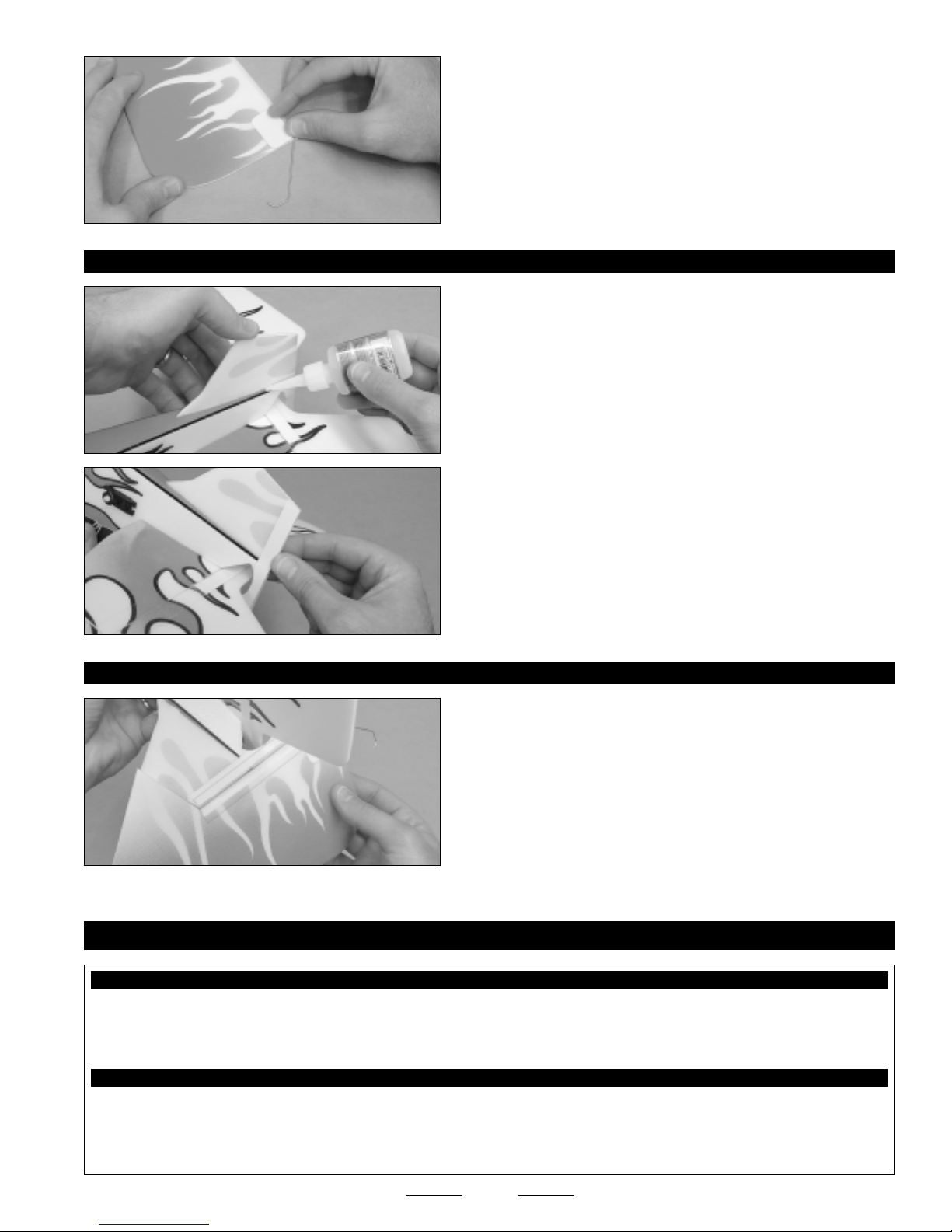
❑Carefully apply one piece of reinforcement board to the top and to
the bottom of the elevator, to reinforce the center section.
☞The reinforcement board is self-adhesive. Make sure to remove
the protective backing before applying it.
❑Slide the elevator into the stabilizer mounting slot, making sure that
the top of the elevator is toward the top of the fuselage.
✦✦
✦✦
✦IMPORTANT✦✦
✦✦
✦You MUST slide the elevator into the stabilizer
mounting slot BEFORE installing the stabilizer. If you don't, it will be
impossible to install the elevator after the stabilizer is glued in place.
❑Measure and draw a vertical centerline across the top of the
stabilizer, perpendicular to the trailing edge.
❑Slide the stabilizer into the fuselage and align it, using the centerline
that you drew as a reference.
❑When satisfied with the alignment, glue the stabilizer to the fuselage.
Make sure to apply a bead of glue to all four joints.
STEP 2: HINGING THE ELEVATOR
❑While holding the elevator tight against the trailing edge of the
stabilizer, apply a strip of clear hinge tape to each side of the top of the
hinge line.
Continued On Next Page ☛☛
☛☛
☛

12
❑Turn the airplane upside down and deflect the elevator up approximately
45º. While holding the elevator up at a 45º angle, apply a strip of clear
tape to each side of the bottom of the hinge line.
❑Push the clear tape gently into the hinge line, then pivot the elevator up
and down several times to ensure free hinge movement in both directions.
❑Apply one piece of reinforcement board to the bottom of each side of
the stabilizer and fuselage glue joint.
STEP 3: INSTALLING THE TAIL SKID
❑Sand a 45º bevel into the right side of the leading edge of the rudder.
Continued On Next Page ☛☛
☛☛
☛
❑Cut a 6" long piece of wire from one pushrod wire.
❑Bend the 6" long pushrod wire into the shape shown and cut off the
excess.
❑Place the landing skid onto the right side of the rudder.
❑Align the landing skid with the front of the beveled leading edge,
then push the wire down firmly to make an impression of the tail skid
onto the foam.
❑Carefully cut a shallow groove in the rudder, using the impression
left in the foam as a guide.
☞Don't cut too deeply. You don't want to cut through the other side of
the rudder.
13
STEP 4: INSTALLING THE VERTICAL STABILIZER
❑Glue the vertical stabilizer to the fuselage, making sure that the
stabilizer is lined up straight and that the trailing edge is centered with
the back of the fuselage.
❑Apply one piece of reinforcement board onto each side of the stabilizer
and fuselage to strengthen the glue joint.
❑Glue the tail skid into the rudder, then apply a piece of reinforcement
board over the glue joint to strengthen the mounting area.
STEP 5: HINGING THE RUDDER
❑Hinge the rudder, using the same techniques that you used to hinge
the elevator.
❑Pacer Zap-O C/A+
❑Pacer Aerosol Zip-Kicker
❑Excel Modeling Knife
❑Scissors
❑Top Wing - 1
❑Bottom Wing - 1
❑Wing Struts - 2
❑Ruler
❑Pencil
❑Builder's Triangle
YOU'LL NEED THE FOLLOWING PARTS FROM THE KIT:
YOU'LL NEED THE FOLLOWING TOOLS AND SUPPLIES:
SECTION 8: TOP AND BOTTOM WING INSTALLATION
❑Assorted Reinforcement Board - 1
❑Carbon Support Rods - 1
Continued On Next Page ☛☛
☛☛
☛

14
STEP 1: INSTALLING THE AILERON SERVO
❑Carefully punch out the die-cut pieces from both wings, then flex the
ailerons up and down several times to free up the hinge joints.
❑Install the aileron servo into the bottom of the bottom wing. Use
foam-friendly C/A to secure it into place.
✦✦
✦✦
✦IMPORTANT✦✦
✦✦
✦The servo output shaft should be toward the front
of the wing.
☞Make sure to install the servo onto the bottom of the wing. The
bottom has the large Wild Fly 3D logo on it.
STEP 2: INSTALLING THE BOTTOM WING
❑Run the aileron servo lead through the precut hole in the support
tray, then glue the wing to the fuselage, making sure that the wing is
seated firmly against the fuselage. There should be no gaps between
the two parts.
STEP 3: INSTALLING THE RECEIVER AND ESC
❑Plug the elevator, rudder, aileron and ESC leads into your receiver,
then mount the receiver to the top of the support tray, using a piece of
double-sided tape (not included).
❑Run the antenna down through the support tray and out the bottom
of the fuselage. Secure the end of the antenna to the back of the
fuselage, using a piece of clear tape.
❑Mount your ESC to the fuselage side in the forward compartment,
using a piece of double-sided tape (not included).
✦✦
✦✦
✦IMPORTANT✦✦
✦✦
✦The ESC battery plug will need to be pulled through
the precut hole in the top of the fuselage. Position your ESC far
enough forward so that the plug will reach through the hole.
✦✦
✦✦
✦IMPORTANT✦✦
✦✦
✦The receiver and ESC are mounted inside the fuselage. Once the top section of the fuselage is glued into
place, the receiver and ESC will become inaccessible. Later, we will show you how to make an inconspicuous hatch cover in the
side of the fuselage to access the receiver and ESC whenever necessary. So, for now, make sure that when you install your
receiver and ESC, you make all the necessary connections for proper operation.
Continued On Next Page ☛☛
☛☛
☛

15
❑Glue the fuselage top section into place, then cut off the foam tabs
flush with the sides of the fuselage.
✦✦
✦✦
✦IMPORTANT✦✦
✦✦
✦Remember to pull the ESC battery plug out through
the precut hole in the fuselage top. The flight battery will be mounted
conveniently on top of the fuselage, between the two top wing supports.
STEP 4: INSTALLING THE TOP WING
❑Fold one piece of reinforcement board 90º along the molded crease.
❑Carefully make four centered cuts, each spaced 3/32" apart, through
both sides of the reinforcement board.
❑Cut away the material from inside the two center cuts.
❑Push the two 3/32" wide sections out 90º to form a bracket, as shown.
☞The end of the carbon support rod will mount into the middle of the
bracket.
❑Repeat the previous procedures to make three more reinforcement
board brackets. You should make a total of four.
❑Apply one reinforcement board bracket to each side of the fuselage
and wing joint. Position the center of each piece 1-9/16" back from the
leading edge of the wing (at the fuselage side).
❑Glue the two wing struts to the top of the wing. Use a builder's
triangle or square to make sure that the wing struts are perpendicular to
the wing.
✦✦
✦✦
✦IMPORTANT✦✦
✦✦
✦Note the direction the wing struts are mounted. They
should both be angled forward when viewed from the side.
Continued On Next Page ☛☛
☛☛
☛
16
❑Glue the top wing to the top wing supports and to the wing struts.
✦✦
✦✦
✦IMPORTANT✦✦
✦✦
✦Glue the top wing on with the airplane upside down.
This will ensure that the top wing is glued into place flat with no twists
or bows.
❑Apply the two remaining reinforcement board brackets to the inside
of the top wing and wing strut joint. Position the center of each piece
1-3/16" back from the leading edge of the top wing (at the wing strut).
✦✦
✦✦
✦IMPORTANT✦✦
✦✦
✦Make sure to apply the reinforcement board
brackets to the underside of the TOP wing.
❑Insert the ends of each carbon support rod into the pocket in the
reinforcement board brackets, then glue the carbon support rods to the
brackets, using a generous amount of glue.
❑Apply the remaining pieces of reinforcement board to the top of both
center wing supports and to the bottom of both wing struts.
❑# 1 Phillips Head Screwdriver
❑Wire Cutters
❑Needle Nose Pliers
❑Magnum Z-Bend Pliers
❑Assorted Reinforcement Board - 1
❑Pushrod Wires - 6
❑Excel Modeling Knife
❑Ruler
❑Pencil
YOU'LL NEED THE FOLLOWING PARTS FROM THE KIT:
YOU'LL NEED THE FOLLOWING TOOLS AND SUPPLIES:
SECTION 9: CONTROL LINKAGES INSTALLATION
❑Plastic Parts Tree - 1
Continued On Next Page ☛☛
☛☛
☛
17
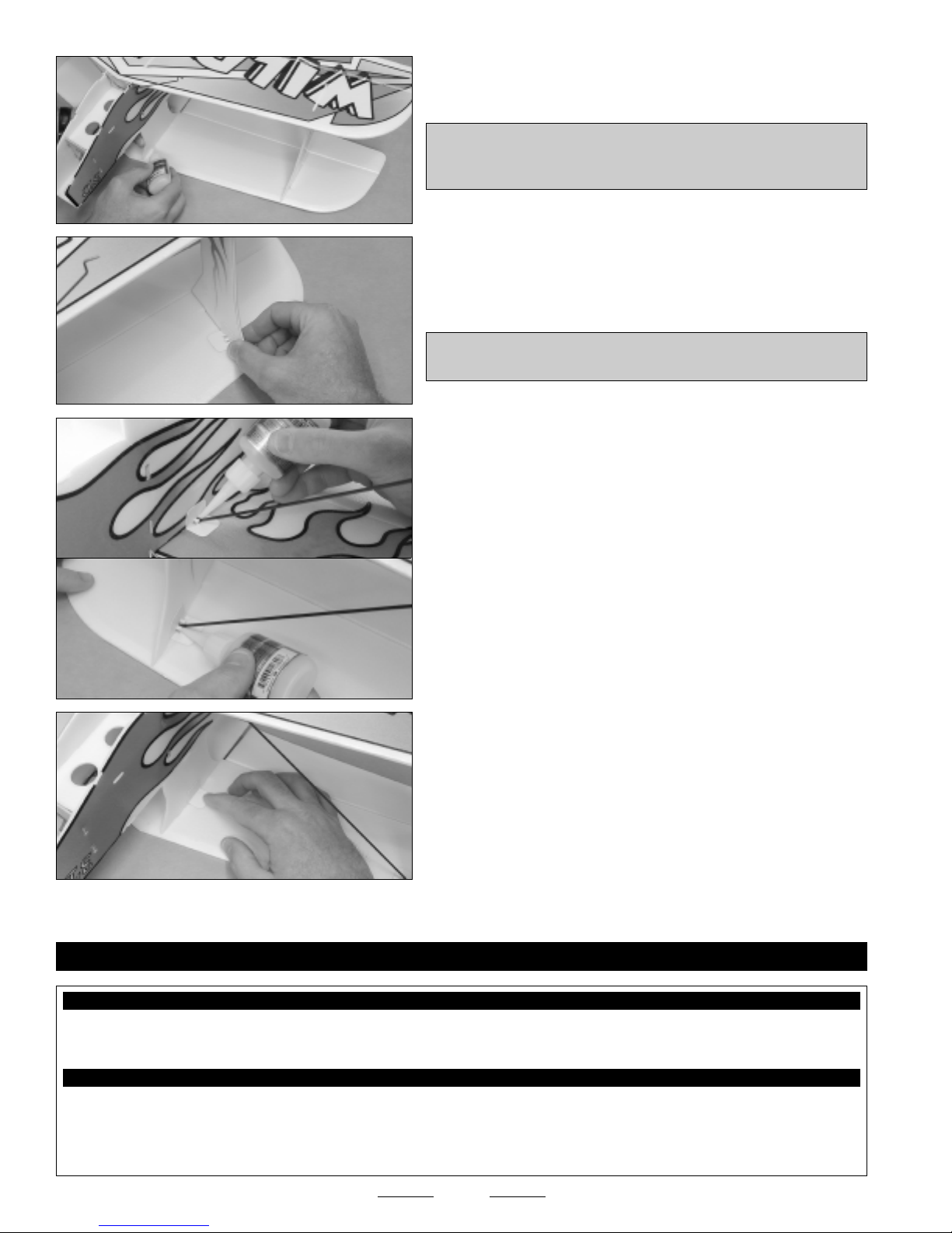
STEP 1: INSTALLING THE ELEVATOR AND RUDDER PUSHRODS
❑Cut a 3/8" long slot through the right side of the elevator for the
elevator control horn. Position the slot 3/4" out from the fuselage side
and 1/2" behind the hinge line.
❑Push a control horn through the slot, then secure it into place with a
control horn backplate.
✦✦
✦✦
✦IMPORTANT✦✦
✦✦
✦Make sure that the flat portion of the control horn
backplate faces away from the elevator, and push the backplate over
the end of the control horn until you hear it "click" firmly into place.
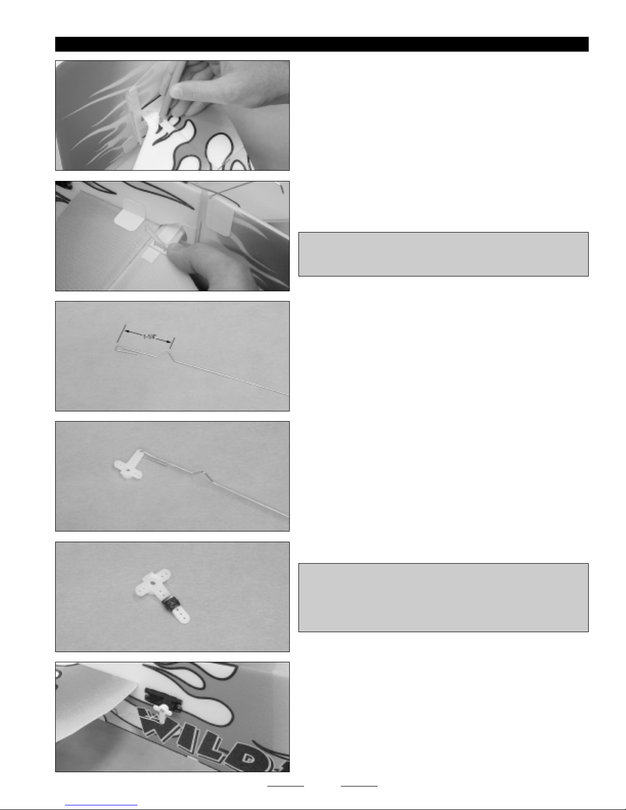
❑So that you can adjust the length of the pushrod after it's installed,
carefully make a V-Shaped bend 1-1/4" behind the prebent loop in one
pushrod wire.
❑Install the pushrod wire into the outermost hole in your servo arm.
✦✦
✦✦
✦IMPORTANT✦✦
✦✦
✦Depending on the length of your servo arm, you
may not be able to get full 3D control throws. If this is the case, you
can attach the servo arm extension from the plastic parts tree to your
servo arm using thread and glue. This will effectively lengthen your
servo arm, making it possible to get extreme 3D control throws.
❑Center the elevator servo, then attach the servo arm to the servo,
making sure that it's centered and pointing down.
Continued On Next Page ☛☛
☛☛
☛

18
❑Center the elevator, then mark where the pushrod wire crosses the
holes in the control horn.
❑Make a Z-Bend in the pushrod wire, then attach the pushrod wire to
the middle hole in the control horn.
❑Double-check that both the servo arm and the elevator are centered.
If the elevator is not centered, adjust the width of the V-Shaped bend
to lengthen or shorten the pushrod wire and center the elevator.
❑Apply one piece of reinforcement board onto the left side of the
rudder. To position the reinforcement board properly, the precut slot in
the reinforcement board should be lined up with the molded slot in
the rudder.
☞The molded slot is located 3-3/8" up from the bottom of the rudder.
❑Cut a slot through the rudder, using the precut slot in the reinforcement
board as a guide.
❑Install the control horn and back plate onto the rudder.
❑Install the rudder servo arm and pushrod, using the same techniques
that you used to install the elevator servo arm and pushrod. Note that
the servo arm should point up and that the pushrod wire should be
installed into the middle hole in the control horn.
❑Double-check that both the servo arm and the rudder are centered.
Adjust the width of the V-Shaped bend to lengthen or shorten the
pushrod wire and center the rudder.
STEP 2: INSTALLING THE AILERON PUSHRODS
❑Apply one piece of reinforcement board onto the bottom of each
bottom wing aileron. To position the pieces of reinforcement properly,
the precut slot in the reinforcement board should be lined up with the
molded slot in the ailerons.
Continued On Next Page ☛☛
☛☛
☛

19
❑Install the control horns, using the same techniques that you used to
install the rudder control horn.
❑Make a V-Shaped bend in two pushrod wires, then install the two
pushrod wires into the outermost holes in your servo arm.
❑Install the aileron servo arm and the two pushrod wires, using the
same techniques that you used to install the elevator and rudder
pushrod assemblies.
❑Double-check that the servo arm and both ailerons are centered.
Adjust the width of the V-Shaped bends to lengthen or shorten the
pushrod wires and center the ailerons.
STEP 3: INSTALLING THE AILERON LINK RODS
❑Make a 90º bend in the end of one pushrod wire, then slide the end
of the pushrod wire through one link rod mounting bracket.
❑Carefully make a second 90º bend in the pushrod wire to prevent the
pushrod wire from pulling out, then cut off the excess.
❑Install the link rod bracket onto the top of one bottom wing aileron,
using the same techniques that you used to install the control horns.
✦✦
✦✦
✦IMPORTANT✦✦
✦✦
✦The center of the link rod mount should be 6-1/4"
out from the inside edge of the aileron and the back edge of the link
rod mount should be 1/16" in front of the trailing edge of the aileron.
❑Install a second link rod mount on the bottom of the corresponding
top wing aileron. Like the bottom link rod mount, the top link rod mount
should be installed 6-1/4" out from the inside edge of the aileron.
❑Center both ailerons, then measure and bend the pushrod wire, and
secure it to the top link rod mount.
❑Repeat the previous procedures to install the second link rod assembly.
20
❑Pacer Zap-O C/A+
❑Pacer Aerosol Zip-Kicker
❑# 1 Phillips Head Screwdriver
❑Front Fuselage Bottom - 1
❑Plastic Parts Tree - 1
❑Excel Modeling Knife
❑Electric or Hand Drill
❑1/16" Drill Bit
YOU'LL NEED THE FOLLOWING PARTS FROM THE KIT:
YOU'LL NEED THE FOLLOWING TOOLS AND SUPPLIES:
SECTION 10: FINAL ASSEMBLY
❑Motor and Gear Box - 1
❑Motor Mounting Screws - 3
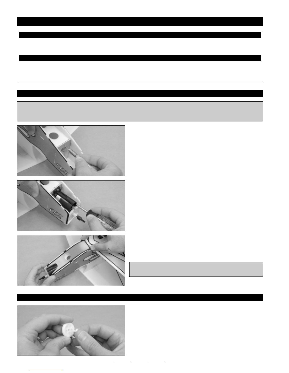
STEP 1: INSTALLING THE MOTOR
❑Drill three 1/16" diameter pilot holes through the firewall, using the
punch marks on the firewall as a guide.
✦✦
✦✦
✦IMPORTANT✦✦
✦✦
✦If you're using your own motor, check to see if one of the extra motor mounting plates is compatible with your
motor mounting system. If so, you can glue the plate to the front of the firewall and use that to mount your motor to. The firewall
that is installed has prepositioned holes to mount the stock motor and gear box.
❑Install the motor and gear box assembly, using the three wood screws
provided.
☞If the plug on the motor does not match the plug on your ESC, you'll
need to change the plug on the motor before installing it.
❑Glue the front fuselage bottom into place, then cut off the foam tabs
flush with the sides of the fuselage.
✦✦
✦✦
✦IMPORTANT✦✦
✦✦
✦You may need to trim the front edge of the fuselage
bottom to fit around the bottom of the motor and gear box assembly.
STEP 2: INSTALLING THE WHEELS
❑Slide one plastic wheel retainer into one plastic wheel.
Continued On Next Page ☛☛
☛☛
☛
Table of contents
Other Sport Flyers Toy manuals


Popular Toy manuals by other brands

FUTABA
FUTABA GY470 instruction manual

LEGO
LEGO 41116 manual

Fisher-Price
Fisher-Price ColorMe Flowerz Bouquet Maker P9692 instruction sheet

Little Tikes
Little Tikes LITTLE HANDIWORKER 0920 Assembly instructions

Eduard
Eduard EF-2000 Two-seater exterior Assembly instructions

USA Trains
USA Trains EXTENDED VISION CABOOSE instructions


