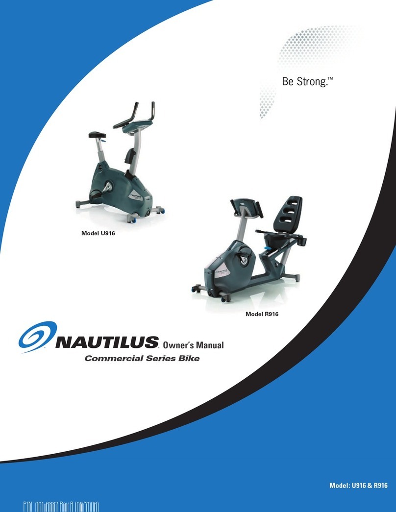
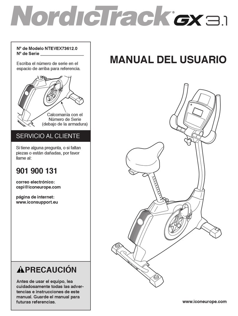
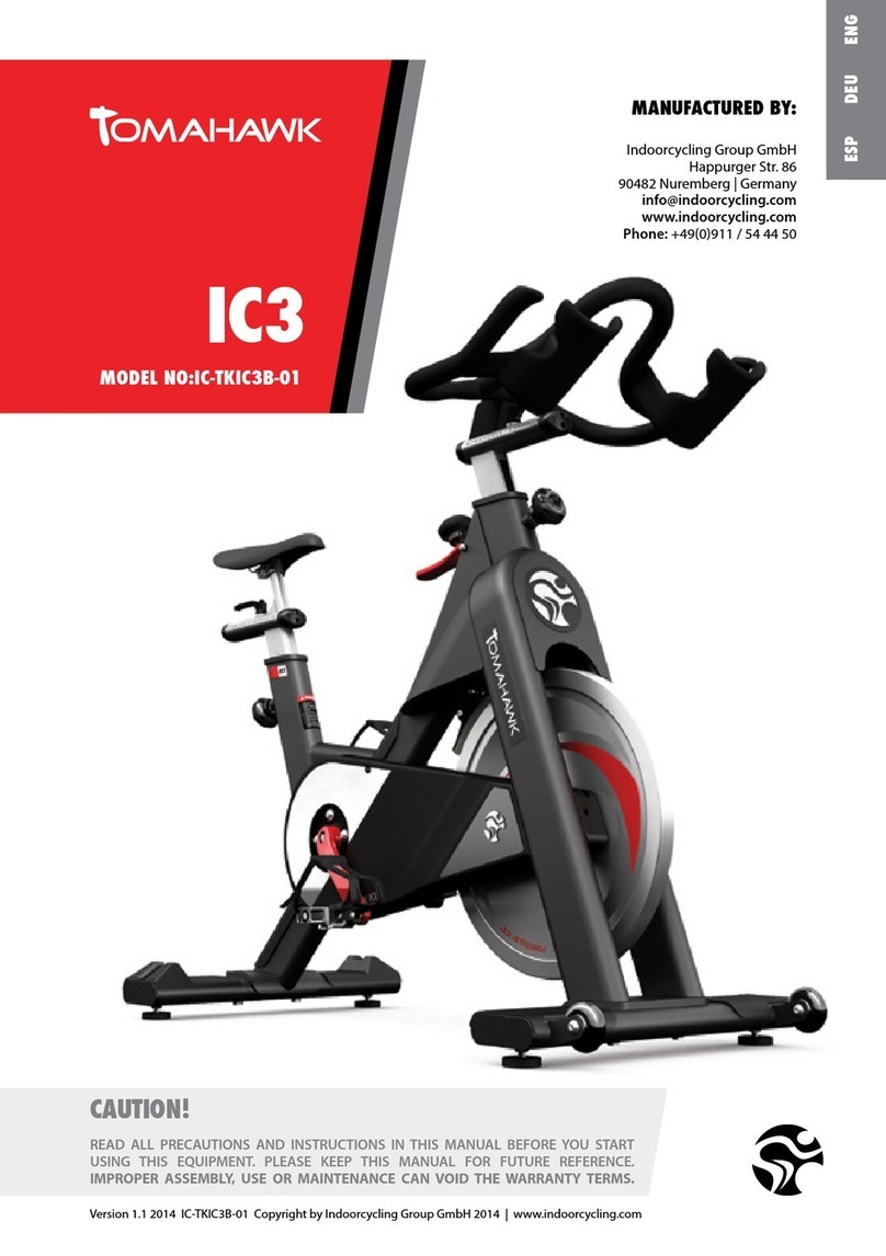
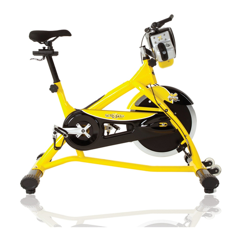
Sportop RB300 Operation manual

ENGLISH
RB300
MODEL:
Owner's Operating Ma nua l

Main Frame Front Stabilizer
Rear Stabilizer
Central Support Tube
Front Handle Bar
Monitor Saddle Pad
Back Pad
Back Pad Support Tube
-1-
Side Handle Bar
(J1) Water Bottle
(J2) Bottle Holder


-3-
Turn the arron of adjust handle (N11) toward
the left and then insert adjust handle (N11)
into alxe .
N11
A
FIGURE_1
ASSEMBLY THE REAR & FRONT STABILIZER
Fix the rear stabilizer(C) with the main frame(A) by screw(N1), washer(N2) and spring washer(N15).
Then, fix the front stabilizer(B) with the main frame(A) by screw(N3), washer(N2)
and spring washer(N15).
** After you finish assembly FIGURE 1, if the machine can’t stand stable,
you can use adjusted stabilizer(C1) to adjust the machine.
A
C
B
N2
N3
N1
N2
C1
N15
N15

-4-
FIGURE_2
ASSEMBLY THE CENTRAL SUPPORT TUBE
A
First, release the screws(N12) from the main frame.
N12
M4
M3 N6
E1
E2
A2
A1
E
Step 1. Connect the sensors, (E2) with (A1), (E1) with(A2).
Step 2. Equip central support tube(E) into main frame(A) and
use screws(N12) to tighten.
Step 3. Slide decoration cover(M3,M4) assembly
the central support tube(E) by screw(N6).
FIGURE_3
ASSEMBLY THE FRONT HANDLE BAR & THE
MONITOR & THE BOTTLE HOLDER
H
D
N9
H1
E
Equip front handle bar(D) onto the iron plate of
central support tube(E) and tighted it by nuts(N9).
E2 E1
Step 1. Remove 4 pieces of screws (H1) from
console (H).
Step 2. Connect console wires (E1 & E2 ) to the
console.
Make sure that the wires are connected together
properly.
Fix the console (H) onto the central supporting
tube (E) using screws (H1).
J1
Release the two screws(N14) from the central
tube (E), equip the bottle holder (J2) with the
central tube (E) by the two screws(N14).
After then, put water bottle (J1) into bottle holder.
J2
N14*2

Fix the back pad support tube(G) with the main frame(A)
by screws(N4) & washers(N2).
Step 1. Then, connect the sensor(F5 & F4)) with the
control sensor(A2).
FIGURE_4
ASSEMBLY FOR BACK PAD TUBE &
THE SIDE HANDLE BAR
A
N2
Step 2. Fix the side handle bar(F) on the main frame(A)
using the disassembled screws(N16) and washer(N2).
F
K
L
G
N7
N2
N10
Step 1. Equip back pad(L) onto back pad tube(G) and
tight it by screws(N7).
Secure the saddle pad(K) onto the side handlebar (F)
by washers(N2) and screws(N10).
FIGURE_5
ASSEMBLY FOR BACK PAD & THE SADDLE PAD
G
F
N16
N2
F5
F4
N4
A2

-6-
M5
FIGURE_6 ASSEMBLY THE BAR
Insert the bar(M5) into the main frame
(A) and use stopping screws(N13)
to fix it.
A
N13
FIGURE_7 ASSEMBLY THE PEDAL
Attach the right pedal to right crank. The right pedal
thread into the crank in a clockwise direction.
The same assembly way for left pedal with left crank.

-7-
FIGURE_8 HOW TO USE THE ADAPTOR
Position machine consideration for convenience,
using the adaptor, there is one adaptor hole located
at the rear of the machine.
Push the handle bar and adjust the back pad
section to have different position as required.
FIGURE_9 HOW TO ADJUST THE BACK PAD
FIGURE_12 HOW TO ADJUST THE
SEAT PAD
Step 1. Pull up the stop bar(G44) and adjust the
seat to a comfortable distance you required,
then pull down.
PULL UP
G44

-8-
PULL
UP
PUSH
DOWN
M7
The front stabilizer has built-in transport wheels. Stand at front of the machine
and lift it up until the weight of the machine is transferred to the transport wheels.
You can now easily move the machine to a new location.
FIGURE_12 HOW TO MOVE THE MACHINE
FIGURE 11
HOW TO ADJUST SITTING POSITION ANGLE
Using bar (M7) via pull up direction for inclination and
push down for declination.

A
J1
J2
M1
M2
M6
N11*3
B
C
N1*2
N2*15
N2*15
N3*2
B1*2
B2*2
B3*4
C1
M3
M4
N6
E
H1*4
E1
E2
N9*2
N14*2
D
D1*4
H
K
N2*15
N10*4
L
N7*4
F
N16*3
F1*2
F2
F3*2
F4
F5
F6*2
F7*2
F8*2
F9*2
F10*2
F11*2
F12
F13
F14*4
F15*4
F16*4
N2*15
M5
A2
N4*4
N2*15
N12*4
N13
G
G1
G2
G3 G4
G5
G6
G7*2 G8*2
G9*2 G10
G11
G12 G13*4
G14
G15
G16
G17
G18
G19*2
G20*4
G21*4
G28*6
G23*4
G24*6
G25*6
G26*6
G27*6
G27*6
G29*2
G30
G31
G32
G33*4
G34*4
G35
G36
G37
G38
G39
G40*2
G41
G42
G43 G44
G45G46
G47
G48
G49
G50
G51
A2
A1
N15*4
N15*4
N13-1
C1-1
G52
G53*2
G51-1

A1
A2
A
A3
A4*4
A5
A6
A7
A8*2
A9
A10
A11*4
A12
A13*2
A14*2
A15
A16
A17
A18
A19
A20*2
A21
A22
A23
A25
A26*2
A27
A30*2
A29*2
A30*2
A31*2
A32*2
A33
A34
A35
A41 A42*8
A44*2
A45
A47
A48
A49*4
A50*8
A52
A53
A54
A55*4 A56*2
A57
A58
A59*8
A60
A61*4
A62*4
A63*2
A64*2
A65
A66
A67
A68
A69*16
A24
A60-1
A70
A71
A40
A39
A38
A37
A36
A72
A51
A43*4
A50-1*4

P/N DESCRIPTION Q”TY P/N DESCRIPTION Q”TY
1 TUN 15A 1 EMARF NIAM A
1 )MM0011(ROSNES 1A 1 LEEHW GNIVIRD 25A
1 CITENGAM 35A 1 )MM0531(ROSNES 2A
1 ELXA 45A 1 ROTOM 3A
4 WERCS 55A 4 GNISUOH ROSNES 4A
2 GNIRAEB 65A 1 )MM059(ROSNES 5A
1 ) L( GNISUOH YELLUP 75A 1 WERCS 6A
1 ) R( GNISUOH YELLUP 85A 1 REDLOH ROSNES 7A
8 WERCS 95A 2 GNIRAEB 8A
1 TUN 06A 1 HSUB 9A
1-06A 1 TUN 01A 1 TUN
4 REHSAW 16A 4 WERCS 11A
26A 1 ELBAC NOISNET 21A SCREW 4
2 TUN 36A 2 WERCS 31A
2 PAC DNE 46A 2 REHSAW 41A
1 )L(REVOC NIAHC TNORF 56A 1 GNISUOH CITENGAM 51A
1 )R(REVOC NIAHC TNORF 66A 1 )MM059(ERIW ERONES 61A
1 )R(REVOC NIAHC RAER 76A 1 TLEB 71A
1 )L(REVOC NIAHC RAER 86A 1 CITENGAM 81A
61 WERCS 96A 1 ELXA 91A
1 )L(KNARC 07A 2 GNIRAEB 02A
1 )R(KNARC 17A 1 GNIRAEB YAW ENO 12A
1 GNIRPS 27A 1 GNIRAEB 22A
1 REZILIBATS TNORF B 1 YLLUP 32A
2 PAC DNE 1B 1 REHSAW 42A
2 LEEHW 2B 1 GNIRAEB 52A
4 WERCS 3B 2 PILC C 62A
1 REZILIBATS RAER C 1 TUN 72A
1 PAC DNE 1C 2 WERCS 92A
2 TUN 03A C1-1 1 PAC DNE
2 TUN 13A DFRONT HANDLE BAR 1
2 DLEIHS LEETS 23A D1 4 PAC DNE
1 EBUT TROPPUS LARTNEC E 1 GNISUOH CITENGAM 33A
1 )MM005(ERIW ROSNES 1E 1 TUN 43A
1 )MM005(ERIW ROSNES 2E 1 WERCS 53A
1 RAB EKDNAH EDIS F 1 WERCS 63A
2 PAC DNE 1F 1 TUN 73A
1 PAC DNE 2F 1 REHSAW 83A
2 PAC DNE 3F 1 REHSAW 93A
1 )MM056()L(ERIW ROSNES 4F 1 TUN 04A
A41 STRIP OF TRACKING HOUSING 1 F5 SENSOR WIRE(L)(650MM) 1
2 PAC DNE 6F 8 WERCS 24A
4 WERCS 34A F7 SENSOR BOX(BELOW) 2
2 GNISUOH MUNIMULA 44A F8 SENSOR BOX(ABOVE) 2
1 KCART MUNIMULA 54A F9 SCREW 2
A47 ALUMINUM HOUSING (REAR) 1 F10 CONTROL BOX(BELOW) 2
A48 ALUMINUM HOUSING (FRONT) 1 F11 CONTROL BOX(ABOVE) 2
A49 SCREW 4 F12 1 )R(NOTTUB RALYM
31F 8 WERCS 05A 1 )L( NOTTUB RALYM
41F 4 WERCS 1-05A SCREW 4

P/N DESCRIPTION Q”TY P/N DESCRIPTION Q”TY
F16 4 LATEM TEEHS ROSNES 1 ELXA 14G
GBACK PAD SUPPORT TUBE 1 1 TUN 24G
G1 1 PAC DNE 1 GNIRPS 34G
G2 SADDLE BASEMENT 1 TFAHS ETATOR 44G 1
G3 ROTATE RECIPROCATOR 1 WERCS 54G 1
G4 SCREW 1 HSUB 64G 1
1 TUN 74G 1 REHSAW 5G
1 WERCS 84G 1 TUN 6G
1 TUN 94G 2 WERCS 7G
2 REHSAW 8G 1 PIRG ELXA 05G
G9 POWDER METALLURGY 1 ELXA GNITSUJDA 15G 2
1-15G 1 HSUB 01G 1 TEKCARB
1 HSUB 25G 1 )L( EBUT TAES FO REVOC 11G
2 REHSAW GNIRPS 35G 1 )R( EBUT TAES FO REVOC 21G
1 ELOSNOC H 4 WERCS 31G
4 WERCS 1H 1 WERCS 41G
1 RENDNILYC SAG 51G 1 ELTTOB RETAW 1J
1 REDLOH ELTTOB 2J 1 GNIRPS 61G
1 ELDDAS K 1 WERCS 71G
1 DAP KCAB L 2 TUN 81G
1 )L(LADEP 1M 2 TEKCARB 91G
1 )R(LADEP 2M 4 WERCS 02G
3M 4 REHSAW 12G CENTRAL SUPPORTING TUBE COVER
(L) 1
4M 4 REHSAW 32G CENTRAL SUPPORTING TUBE COVER
(R) 1
1 RAB 5M 6 TUN 42G
1 ROTPADA 6M 6 REHSAW 52G
2 001X8M WERCS 1N 6 HSUB 62G
51 61X8M REHSAW 2N 6 LEEHW 72G
2 02*8M WERCS 3N 6 WERCS 82G
4 51X8M WERCS 4N 2 WERCS 92G
1 02X4M WERCS 6N 1 TNEMESAB GNIVOM 03G
4 04X4/1 WERCS 7N 1 ) R( GNISUOH GNIDILS 13G
2 8M TUN 9N 1 )L( GNISUOH GNIDILS 23G
4 53X8M WERCS 01N 4 REHSAW 33G
3 ELDNAH TSUJDA 11N 4 WERCS 43G
G35 SCREW 4 WERCS 21N 1
1 WERCS 31N 1 REHSAW 63G
1-31N 1 TUN 73G 1 WERCS
2 51*5M WERCS 41N 1 WERCS 83G
4 8M REHSAW GNIRPS 51N 1 HSUB 93G
3 03X8M WERCS 61N 2 REHSAW 04G

BUTTON FUNCTIONS
DISPLAY FUNCTIONS
TIME Time will count up from 00:00 to maximum 99:00 with each increment
is 1 minute.
SPEED Displays current training speed. Maximum speed is 99.9 KM/H or
ML/H.
RPM Displays the Rotation Per Minute. Display range 0~100 RPM
DISTANCE Accumulates total distance from 00:0 up to 99.9 KM or ML. The user
may preset target distance data by turning the UP/DOWN joggle wheel.
Each incensement is 0.1KM or ML.
UP To make upward adjustment to each function data or increase
training resistance.
DOWN To make downward adjustment to each function data or decrease
training resistance.
ENTER To confirm all settings.
START
/ STOP
RESET To reset current setting and have the monitor switch to initial
training mode for selection. Press the RESET button for 2 seconds
under standby mode for a Total Reset.
RECOVERY To active RECOVERY function.
To start or stop workout.
Turn the START/ STOP joggle wheel under standby mode,
it can be a quick start key to the Manual Program.

CALORIES Accumulates calories consumption during training from 0 to maximum
990 calories. Each unit for increase or decrease is 10 KCL.
(This data is a rough guide for comparison of different exercise sessions
which can not be used in medical treatment.)
PULSE User may set up target pulse from 0 - 30 to 230
WATTS Display current workout watts. Display range 0~999.
POWER ON
1. Connect power supply to the monitor or press the RESET button for 2 seconds, the LCD
will display all segment with a long- beep sound for 2 seconds and display 78.0 in below
(FIGURE 1 & 2).
2. User may turn the UP/DOWN joggle wheel to select User 1~4 and press ENTER for
confirmation (FIGURE 3~4).
And then preset user information for SEX, AGE, HEIGHT and WEIGHT. (FIGURE 4~7)
FIGURE 1 FIGURE 2 FIGURE 3 FIGURE 4
FIGURE 5 FIGURE 6 FIGURE 7 FIGURE 7
PROGRAMMING MODE
1. Program selections are MANUAL PROGRAM USER PROGRAM H.R.C. WATT
(FIGURE 8~12)

2. Use UP/DOWN joggle wheel to select the program you want and press ENTER to confirm.
Or press START/STOP button to start MANUAL mode immediately.
FIGURE 8 FIGURE 9 FIGURE 10 FIGURE 11
FIGURE 12
QUICK START IN MANUAL
1. Press ENTER to enter MANUAL program, and the screen is blinking (FIGURE 13).
2. Press START/STOP to start exercising. The resistance level is adjustable during exercising
(FIGURE 14).
3. User can press START/ STOP to stop exercising
FIGURE 13 FIGURE 14
-15-

MANUAL MODE
1. After selecting MANUAL mode (FIGURE 13), user can use UP/DOWN joggle wheel to
increase or decrease level (from 1 to 16) and press ENTER to confirm.
2. User may preset exercise data (TIME, DISTANCE, CALORIES, PULSE), and press
START/STOP to start exercise.
User can press RESET to return to the MANUAL setting
3. Level is adjustable during training.
FIGURE 13 FIGURE 14 FIGURE 15 FIGURE 16
FIGURE 17 FIGURE 18 FIGURE 19 FIGURE 20
USER SELECT U1-U4
PRESS
RESET 3 SEC
TO RESET
CLOCKWISE OR
ANTI-CLOCKWISE
MANUAL mode
PRESS
ENTER
CLOCKWISE OR
ANTI-CLOCKWISE
CLOCKWISE OR
ANTI-CLOCKWISE
PRESS
ENTER
PRESS
ENTER
CLOCKWISE OR
ANTI-CLOCKWISE
CLOCKWISE OR
ANTI-CLOCKWISE
PRESS
ENTER CLOCKWISE OR
ANTI-CLOCKWISE
CLOCKWISE OR
ANTI-CLOCKWISE
PRESS
ENTER
PRESS
ENTER
FUNCTION SELECT
T
I
M
E
P
U
L
S
C
A
L
O
R
I
E
S
D
I
S
T
A
N
C
E
E
CLOCKWISE OR
ANTI-CLOCKWISE
PRESS
ENTER
START/
STOP

FIGURE 21 FIGURE 22 FIGURE 23 FIGURE 24
PROGRAM MODE
1. After entering PROGRAM mode, user and turn the UP/DOWN joggle wheel to select
program profile from P1 to P12, then press ENTER to confirm.
2. User can preset the TIME data then press START/STOP to start exercise.
3. After start training, TIME will be counted down. When the TIME is counted to 0, the
screen is flashing and the alarm is ringing. User can press any button to stop the alarm.
USER SELECT U1-U4
PRESS
RESET 3 SEC
TO RESET
CLOCKWISE OR
ANTI-CLOCKWISE
PROGRAM mode
PRESS
ENTER
CLOCKWISE OR
ANTI-CLOCKWISE
CLOCKWISE OR
ANTI-CLOCKWISE
PRESS
ENTER
PRESS
ENTER
CLOCKWISE OR
ANTI-CLOCKWISE
CLOCKWISE OR
ANTI-CLOCKWISE
PRESS
ENTER CLOCKWISE OR
ANTI-CLOCKWISE
PRESS
ENTER
PRESS
ENTER
FUNCTION SELECT
T
I
M
E
CLOCKWISE OR
ANTI-CLOCKWISE
PRESS
ENTER
PROGRAM SELECT P1 to P12
P1 P2
P3
P4
P5
P7 P6
P8
P9
P10
P11
P12
CLOCKWISE OR
ANTI-CLOCKWISE
-17-

to 0, the screen is flashing and the alarm is ringing. User can press any button to stop the
alarm.
FIGURE 25 FIGURE 26 FIGURE 27 FIGURE 28
FIGURE 29
USER PROGRAM
1. After entering USER PROGRAM mode, the first column of the profile is blinking
(FIGURE 25).
User may turn the joggle wheel to adjust the resistance level (FIGURE 26)
to create his/her own profile.
2. After setting (from column 1 to column 20), user may hold on pressing MODE button for 2
seconds to quit profile setting and enter TIME setting.
3. While making the profile setting, user can press RESET and return to the menu.
4. After start training (FIGURE 27~29), TIME will be counted down. When TIME is counted
USER SELECT U1-U4
PRESS
RESET 3 SEC
TO RESET
CLOCKWISE OR
ANTI-CLOCKWISE
USER mode
PRESS
ENTER
CLOCKWISE OR
ANTI-CLOCKWISE
CLOCKWISE OR
ANTI-CLOCKWISE
PRESS
ENTER
PRESS
ENTER
CLOCKWISE OR
ANTI-CLOCKWISE
CLOCKWISE OR
ANTI-CLOCKWISE
PRESS
ENTER CLOCKWISE OR
ANTI-CLOCKWISE
PRESS
ENTER
PRESS
ENTER
FUNCTION SELECT
T
I
M
E
CLOCKWISE OR
ANTI-CLOCKWISE
PRESS
ENTER
Repeating these opeartion till completing the setting of 20 ranges
CLOCKWISE OR
ANTI-CLOCKWISE
Hold on pressing for 2 seconds
-18-

FIGURE 29 FIGURE 30 FIGURE 31 FIGURE 32
FIGURE 33 FIGURE 34 FIGURE 35 FIGURE 36
USER SELECT U1-U4
PRESS
RESET 3 SEC
TO RESET
CLOCKWISE OR
ANTI-CLOCKWISE
H.R.C. mode
PRESS
ENTER
CLOCKWISE OR
ANTI-CLOCKWISE
CLOCKWISE OR
ANTI-CLOCKWISE
PRESS
ENTER
PRESS
ENTER
CLOCKWISE OR
ANTI-CLOCKWISE
CLOCKWISE OR
ANTI-CLOCKWISE
PRESS
ENTER CLOCKWISE OR
ANTI-CLOCKWISE
PRESS
ENTER
PRESS
ENTER
FUNCTION SELECT
T
I
M
E
CLOCKWISE OR
ANTI-CLOCKWISE
PRESS
ENTER
TRAINING MODE SELECT
.
R
C
G
A
T
%
0
5
%
5
7
%
0
9
CLOCKWISE OR
ANTI-CLOCKWISE
HEART RATE CONTROL
1. After entering HEART RATE CONTROL mode, the screen will show heart rate percentage
55%, 75%, 90% and TARGET. User may select heart rate percentage by turning
UP/ DOWN joggle wheel for training.
2. User can preset the TIME data then press START/ STOP to start exercise.
3. After start training, TIME will be counted down. When the TIME is counted to 0, the
screen is flashing and the alarm is ringing. User can press any button to stop the alarm.
If there is no HR input for 5 seconds, LCD will display until HR signal input.
-19-
Table of contents
Other Sportop Exercise Bike manuals
Popular Exercise Bike manuals by other brands

Sunny Health & Fitness
Sunny Health & Fitness SF-B121021 user manual

Monark
Monark 827E instruction manual

Stamina
Stamina 1310 owner's manual

American Fitness
American Fitness SPR-BK1072A owner's manual

Cateye
Cateye CS-1000 (CYCLO SIMULATOR) Service manual

BH FITNESS
BH FITNESS H9158H Instructions for assembly and use


