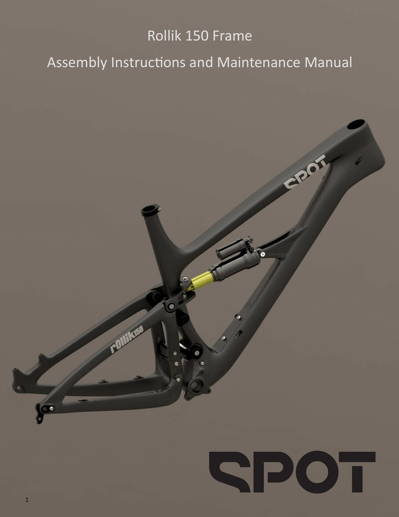
SPOT Mayhem 130 Instructions for use

1
MY21 Mayhem 130 Frames
Assembly Instrucons and Maintenance Manual

2
Table of Contents
Warnings and Precauons
Suspension Setup Instrucons
Mayhem 130 Geometry
Geometry Adjuster Operaon
Component Compability Chart
Tools Required for Assembly of Components onto Frame
Tools Required for Maintenance
Pivot Bearing and O-Ring Specicaons
Leaf Spring Related Precauons
Cable Roung:
Internal Dropper Seatpost Roung
Rear Brake Hose Roung
Rear Derailleur Cable Roung
Boom Bracket Installaon
Frame Disassembly:
Rear Derailleur Hanger Removal/Replacement
Rear Shock Removal/Replacement
Rear Triangle Removal
Shock Yoke and Link Removal
Pivot Bearing Replacement
Main Pivot Bearing Replacement
Rocker Link Bearing Replacement
Frame Reassembly
Rocker Link Reinstallaon
Rear Triangle Reinstallaon
Mayhem 130 Frame Parts Reference
3
4
7
8
12
13
13
14
15
16
18
20
22
23
24
29
34
38
40
43
48
54

3
Warning
Like any sport, bicycling involves risk of injury and damage. By choosing to ride a bicycle, you assume
the responsibility for that risk, so you need to know—and to pracce— the rules of safe and
responsible riding and of proper use and maintenance. Proper use and maintenance of your bicycle
reduces the risk of injury or death.
All bicycles should be assembled and maintained by an authorized bicycle mechanic. If you are not
qualied to assemble, inspect, and maintain your bicycle, please visit your favorite local bike shop or
contact Spot for a referral to a qualied bicycle technician in your area.
This guide covers the details specic to your Living Link™ suspension frame. It does not address
complete bicycle assembly, ng, inspecon, maintenance, or riding techniques. Please refer to the
Spot Brand Bicycle Owner’s Manual for further details.
Under no circumstances shall Spot Brand LLC be held liable for direct, incidental, or consequenal
damages, including, without limitaon, damages for personal injury property damage, or economic
losses, whether based on contract, warranty, negligence, product liability, or and other theory.
A Note on Intended Use
The American Society for Tesng and Materials (ASTM) has established a classicaon standard
for bicycle use, outlined in document ASTM F2043. It is important to use any bicycle within its
intended use classicaon to ensure rider safety, equipment longevity, and warranty coverage.
The Spot Mayhem 130 mountain bikes are classied within Level 3 of this standard:
1This is a set of conditions for the operation of a bicycle on a regular paved surface where the
tires are intended to maintain ground contact.
2This is a set of conditions for the operation of a bicycle that includes Condition 1 as well as un-
paved and gravel roads and trails with moderate grades. In this set of conditions, contact with
irregular terrain and loss of tire contact with the ground may occur. Drops are intended to be
limited to 15cm (6") or less.
3This is a set of conditions for operation of a bicycle that includes Condition 1 and Condition 2 as
well as rough trails, rough unpaved roads, and rough terrain and unimproved trails that require
technical skills. Jumps and drops are intended to be less than 61cm (24").
4This is a set of conditions for operation of a bicycle that includes Conditions 1, 2, and 3, or
downhill grades on rough trails at speeds less than 40 km/h (25 mph), or both. Jumps are in-
tended to be less than 122cm (48").
5This is a set of conditions for operation of a bicycle that includes Conditions 1, 2, 3, and 4; ex-
treme jumping; or downhill grades on rough trails at speeds in excess of 40 km/h (25 mph); or a
combination thereof.

4
Climb/Lockout Lever
• 3 posions– Open, Medium, Firm
• Spot recommends leaving the lever in the
open mode at all mes, including
climbing, due to the eciency of Living
Link. Locking the suspension for climbing
will only make the ride bumpy!
Compression Damping “Open Mode Adjust”
• 3 posions– 1,2,3
• Increases rmness and support on the
compression (downward) stroke of the shock
• Li and turn black dial to adjust
• Aects “Open” seng on blue lever only
• 1—soest, best for lighter riders, less
aggressive riding
• 3—rmest, best for heavier riders, more
aggressive riding
Air spring pressure
• Use included shock pump to increase/decrease
air pressure
• Sets sag / “ride height”
• Spot recommends starng by seng the rear
shock air spring pressure to 85% of your riding
weight (with helmet, pack, gear, etc.) in
pounds. For example, if you weigh 180lbs ready
to ride, you would inate your rear shock to
0.85 X 180 = 153psi.
• Increase pressure (up to +25psi) if you are
booming out frequently. If adding air pressure
does not prevent frequent boom outs, you
may need to upsize your VOLUME SPACER.
• Decrease pressure (up to -15psi) if you are
never using full travel. If reducing air pressure
does not allow you to access full travel you may
need to downsize your VOLUME SPACER.
Rebound Knob
• Adjusts return speed “rebound” of suspension
• Turn clockwise to slow the rebound,
counterclockwise to speed up.
• Adjustment sengs are referenced from “full
slow”. To adjust, turn the red rebound knob
clockwise unl it stops, then slowly unwind the
knob while counng each me it clicks.
• Spot recommended rebound sengs– based on
air spring pressure:
• Increase rebound speed if the bike feels rough
and low on fast secons with successive bumps
• Decrease rebound speed if the bike feels
“bucky”, like riding a pogo sck on successive
bumps.
Pressure (psi) Rebound Seng (clicks
from full slow)
100 10
100-120 9
120-140 8
140-160 7
160-180 6
180-200 5
200-220 4
220-240 3
240-260 2
260-280 1
280-300 Closed
Volume Spacers
• Air volume spacers are installed in the
shock to control how the spring forces
increase as the shock is compressed
• A larger volume spacer will make the
shock more progressive and harder to
boom out on big hits and landings
• A smaller volume spacer will make the
shock more linear and easier to access full
travel.
• Changing volume spacers is a simple
process. Instrucons for swapping spacers
can be found here:
Fox Shock Volume Spacers
Travel Indicator O-Ring
• The shock will push the o-ring down the damper body as it
compresses
• Measure from the shock can to the o-ring to determine your
max travel usage.
• The Mayhem 130 will show 56-57.5mm at max travel
• NOTE: Using max travel on the Mayhem 130 will not push the
o-ring to end end of the damper body. Boom out occurs with
some 8-9mm (.32-.35in) le below the o-ring
Rear Shock Setup—Fox Float Shocks

5
Low Speed Compression Damping Adjuster
• Increases rmness and support on slow
compression (downward) stroke of the
fork. Firmer sengs will increase support
for bermed turns and “g-out” style slow
compressions.
• Approximately 16 clicks of adjustment
• Turn black dial clockwise to increase
rmness
• Soer: best for lighter riders, less
aggressive riding
• Firmer: best for heavier riders, more
aggressive riding
Air spring pressure
• Use included shock pump to increase/
decrease air pressure
• Sets sag / “ride height”
• Spot recommends starng by seng the fork
air spring pressure to 37% of your riding
weight (with helmet, pack, gear, etc.) in
pounds. For example, if you weigh 180lbs
ready to ride, you would inate your fork to
0.37 X 180 = 67psi.
• Increase pressure (up to +15psi) if you are
booming out frequently. If adding air
pressure does not prevent frequent boom
outs, you may need to upsize your VOLUME
SPACER.
• Decrease pressure (up to –10psi) if you are
never using full travel. If reducing air
pressure does not allow you to access full
travel you may need to downsize your
VOLUME SPACER.
Rebound Damping Adjusters- Under Black Cap
• Adjusts return speed “rebound” of suspension
• Turn clockwise to slow the rebound, counter-
clockwise to speed up.
• Adjustment sengs are referenced from “full
slow”. To adjust, turn the red rebound knob
clockwise unl it stops, then slowly unwind the
knob while counng each me it clicks.
• Spot recommended rebound sengs– based
on air spring pressure:
• Increase rebound speed if the bike feels rough
and low on fast secons with successive bumps
• Decrease rebound speed if the bike feels
“bucky”, like riding a pogo sck on successive
bumps.
Pressure (psi)
Low Speed
Rebound Seng
(clicks from full
slow)
High Speed
Rebound Seng
(clicks from full
slow)
40 98
40-50 87
50-60 76
60-70 65
70-80 54
80-90 43
90-100 32
100-110 21
110-120 10
Volume Spacers
• Air volume spacers are installed in the fork
to control how the spring forces increase
as the shock is compressed
• A larger volume spacer will make the fork
more progressive and harder to boom
out on big hits and landings
• A smaller volume spacer will make the fork
more linear and easier to access full travel.
• Changing volume spacers is a simple pro-
cess. Instrucons for swapping spacers can
be found here:
Fox Fork Volume Spacers
Travel Indicator O-Ring
• The fork seal will push the o-ring up the
stanchion tube as it compresses
• Measure from the seal to the o-ring to
determine your max travel usage.
• The Mayhem 130 comes stock with a
140mm travel fork.
High Speed Compression Damping Adjuster
• Increases rmness and support on fast
compression (downward) stroke of the
fork. Firmer sengs will increase support
for square edge hits and landing jumps
• Approximately 8 clicks of adjustment
• Turn blue dial clockwise to increase
rmness
• Soer: best for lighter riders, less
aggressive riding
• Firmer: best for heavier riders, more
aggressive riding
Fork Setup—Fox 36 GRIP2 Forks

6
Air spring pressure
• Use included shock pump to increase/
decrease air pressure
• Sets sag / “ride height”
• Spot recommends starng by seng the fork
air spring pressure to 50% of your riding
weight (with helmet, pack, gear, etc.) in
pounds. For example, if you weigh 180lbs
ready to ride, you would inate your fork to
0.50 X 180 = 90psi.
• Increase pressure (up to +15psi) if you are
booming out frequently. If adding air
pressure does not prevent frequent boom
outs, you may need to upsize your VOLUME
SPACER.
• Decrease pressure (up to –10psi) if you are
never using full travel. If reducing air
pressure does not allow you to access full
travel you may need to downsize your
VOLUME SPACER.
Rebound Damping Adjuster
• Adjusts return speed “rebound” of suspension
• Turn clockwise to slow the rebound, counter-
clockwise to speed up.
• Adjustment sengs are referenced from “full
slow”. To adjust, turn the red rebound knob
clockwise unl it stops, then slowly unwind the
knob while counng each me it clicks.
• Spot recommended rebound sengs– based
on air spring pressure:
• Increase rebound speed if the bike feels rough
and low on fast secons with successive bumps
• Decrease rebound speed if the bike feels
“bucky”, like riding a pogo sck on successive
bumps.
Pressure (psi)
Low Speed Rebound
Seng (clicks from full
slow)
50 12
50-60 11
60-70 10
70-80 9
80-90 8
90-100 7
100-110 6
110-120 5
120-130 4
Volume Spacers
• Air volume spacers are installed in the fork
to control how the spring forces increase
as the shock is compressed
• A larger volume spacer will make the fork
more progressive and harder to boom
out on big hits and landings
• A smaller volume spacer will make the fork
more linear and easier to access full travel.
• Changing volume spacers is a simple pro-
cess. Instrucons for swapping spacers can
be found here:
Rockshox Fork Boomless Tokens
Travel Indicator O-Ring
• The fork seal will push the o-ring up the
stanchion tube as it compresses
• Measure from the seal to the o-ring to
determine your max travel usage.
• The Mayhem 130 comes stock with a
140mm travel fork.
Compression Damping Adjuster
• Increases rmness and support on
compression (downward) stroke of the
fork. Firmer sengs will increase support
for bermed turns and landing jumps
• Approximately 20 clicks of adjustment
• Turn black dial clockwise to increase
rmness
• Soer: best for lighter riders, less
aggressive riding
• Firmer: best for heavier riders, more
aggressive riding
Fork Setup—Rockshox Pike Select

7
Mayhem 130 Frame Geometry
GEOMETRY - HIGH MODE
SIZE
STL
(mm) STL (in)
ETT
(mm) ETT (in) HTA
HTL
(mm) HTL (in) STAE STAA
WB
(mm) WB (in)
SOH
(mm)
SOH
(in)
S356 14.0 569 22.4 65.7 90 3.5 75.5 71.8 1154 45.4 707 27.8
M407 16.0 593 23.3 65.7 105 4.1 76 72.6 1185 46.7 707 27.8
L457 18.0 615 24.2 65.7 120 4.7 76.5 73.5 1217 47.9 707 27.8
XL 495 19.5 637 25.1 65.7 130 5.1 77 74.3 1246 49.1 707 27.8
SIZE
BBD
(mm) BBD (in)
BBH
(mm) BBH (in)
RC
(mm) RC (in)
FC
(mm) FC (in)
REACH
(mm)
REACH
(in)
STACK
(mm)
STACK
(in)
S31 1.2 344 13.5 435 17.1 719 28.3 415 16.3 597 23.5
M31 1.2 344 13.5 435 17.1 750 29.5 440 17.3 612 24.1
L31 1.2 344 13.5 435 17.1 782 30.8 465 18.3 626 24.6
XL 31 1.2 344 13.5 435 17.1 811 31.9 490 19.3 635 25.0

8
Mayhem 130/150 Geometry Adjuster Operaon
Your Mayhem frame can quickly and easily be switched between a High Mode and a Low Mode to ne tune
its handling behavior. The High Mode will provide quicker steering response and beer pedal clearance,
which can be benecial at lower speeds and when pedaling along rougher terrain. The Low Mode delivers
more relaxed steering and a lower center of gravity, which will make the bike more stable at higher speeds
and in faster corners. Follow the instrucons below to switch between the modes. The selected mode is
indicated on the top of the shock yoke adjacent to the adjuster cap.
Switching from High Mode to Low Mode will slacken the head tube and seat tube angles by ~0.5°
and lower the boom bracket by 7mm (1/4in).
1. Using a 10mm 12-point wrench, unscrew the rear shock nut two full turns (720°). Hold a
nger underneath the shock yoke at the pin to ensure that unscrewing the nut causes the
adjuster cap to rise, instead of pushing the pin down out of the yoke.

9
2. Use the open end of the wrench to turn the adjuster cap 180°. Either direcon will work.

10
3. Once turned to the desired seng, ghten the nut using the closed 12-point end of the 10mm
wrench. Torque to approximately 12N-m (106in-lb).

12
Mayhem 130 Frame Component Compability
Your Mayhem frame was designed to work with the following components. Other components may be
compable, but tment is not guaranteed. For quesons regarding component compability of parts
not listed below please contact Spot.
COMPONENT FIT, STANDARD
HEADSET UPPER: ZS44, LOWER: ZS56
BOTTOM BRACKET BSA THREADED, 73mm SHELL WIDTH
SEATPOST 31.6, INTERNAL DROPPER ROUTING
CHAINRING >51mm CHAINLINE, 30-34t RING
REAR HUB 12 X 148, SRAM UDH MAXLE INCLUDED
REAR BRAKE 160mm STANDARD POST MOUNT, 180mm MAX ROTOR DIAMETER
REAR TIRE 29 X 2.5" / 64mm MAX WIDTH. ACTUAL TIRE WIDTHS CAN VARY FROM PRINTED SIZES
REAR SHOCK 230 X 57.5, FRONT EYELET Ø8 X 25mm, REAR EYELET OPEN, NO BUSHINGS
FORK TRAVEL 140-150mm
WATER BOTTLE 2X BOTTLE MOUNTS, ONE ABOVE AND ONE BELOW DOWNTUBE
SEATPOST COLLAR 35.0mm INNER DIAMETER
CHAINGUIDE ISCG-05 MOUNTS, UPPER GUIDE MUST BE MINIMAL SIZE

13
Tools Required for Assembling a Frame into a Bicycle:
(Complete bikes delivered from Spot will not require these steps.)
• Hex wrenches / bits: 4mm, 5mm, 6mm
• Torx wrenches / bits: T25, T30
• 10mm 12 point box wrench or 10mm 12point socket (with ratchet)
• Torque wrench, 4Nm (35in-lb) to 14Nm (124in-lb) range
• Headset Press
• Boom Bracket Installaon Tools—may vary by BB brand and model
• High-Pressure Waterproof Grease—we recommend Motorex 3000®
• Isopropyl or denatured alcohol—90% or higher concentraon
Tools Required For Rear Triangle Removal/Replacement:
• Torx wrenches / bits, sizes: At least two T30 tools including one L-wrench
• Torque wrench with T30 Torx bit, 4Nm (35in-lb) to 14Nm (124in-lb) range
• Round pin punch, at p, 8-10mm diameter
• Hammer
• Isopropyl or denatured alcohol—90% or higher concentraon
• Medium strength (blue) thread locking compound, such as Locte 243 (blue)

14
Tools Required For Pivot Bearing Replacement:
(In addion to the tools listed above)
• PVC, or other plasc tubes:
27-30mm inner diameter, 45-55mm long
23-25mm inner diameter, 25-30mm long
• An assortment of sockets and extensions for bearing removal, 20-22mm outer diameter
for main pivot bearings, 13-14mm outer diameter for shock yoke pivot bearings
• Several spacers to support the main pivot clevis and upper link for bearing removal and
installaon. These can be made from any hard material, wood, plasc, PVC pipe etc. The
only requirements are that they t into the required openings, are sturdy enough to
support the parts, and are the following widths:
Main Pivot: 62mm (2.44in)
Upper Link Shock Pivot and SS Pivot: 57mm (2.24in)
Upper Link Seat Tube Pivot: 44mm (1.73in)
See pages 35 and 37-38 for illustraons of these spacers’ funcon.
• Arbor press or bench vise for bearing installaon
Pivot Bearing and O-Ring Specicaons:
• Main Pivot Bearings, QTY 2: Enduro 3802 LLU MAX
• Seat Tube Pivot Bearings, QTY 2: Enduro 3802 LLU MAX
• Seat Stay Pivot Bearings, QTY 2: Enduro 3802 LLU MAX
• Shock Yoke Pivot Bearings, QTY 2: Enduro DR 1017 RS MAX
• Main Pivot O-Rings, QTY 4: 1.5 X 18 EPDM
• Seat Tube Pivot O-Rings, QTY 4: 1.5 X 18 EPDM
• Seat Stay Pivot O-Rings, QTY 4: 1.5 X 18 EPDM
• Shock Yoke Pivot O-Rings, QTY 4: 1.5 X 13 EPDM
For individual parts and a complete exploded assembly diagram, please see the last 3 pages
of this manual.

15
Leaf Spring Related Precauons
The Living Link leaf spring, and its associated hardware, which include the 8 T30 Torx
fasteners, main pivot clevis, and cap hardware are to be treated as integral to the rear
triangle of the frame.
Do not aempt to remove or modify the leaf spring!
Doing so is likely to damage the leaf spring, hardware, and possibly the rear triangle itself.
Any quesons or concerns regarding the leaf spring should be directed to Spot:
www.spotbikes.com
customerservice@spotbikes.com
303-278-3955
It is recommended to periodically check the torque on the 8 leaf spring mounng fasteners.
This should be done approximately every 100 hours of ride me, or once per year,
depending on which occurs sooner.
1. Fit your torque wrench with a T30 Torx bit and the shortest extension required to reach
the fasteners.
2. Clamp the bicycle securely in a work stand and remove the rear wheel.
3. Remove the forward shock pivot screw and pin, and swing the shock down and
outwards. Very carefully compress the rear suspension by liing the rear triangle at the
rear dropout area. The leaf spring will inially resist compression, but once past mid
travel, it will tend to pull the rear swingarm upward. Let the suspension come to rest in
the upward posion to gain access to the leaf spring mounng screws. Do not over-
compress the suspension causing a back-bend in the leaf spring. This could damage the
leaf spring and lead to failure.
4. Turning the torque wrench clockwise (as seen looking at the head of the fastener) and
verify that all 8 fasteners are at or above 12N-m (106in-lb).

16
1. Make sure your seatpost collar is installed on the frame. The seatpost cable housing is easiest
to install by feeding from the head tube to the seat tube, but can be fed starng at the seat
tube if necessary. Tape the seatpost cable housing to the guide tube at the head tube end.
Make sure to clean the end of the cable housing and the guide tube with alcohol before
taping. Tape the two together in line, and wrap the tape several mes around the juncon for
sucient contact.
2. While feeding the seatpost cable housing into the frame, gently pull the guide tube out of the
seat tube. If excessive resistance is met, the tape joint may be too bulky and should be
reduced. The cable housing must curve around a relavely small radius between the seat tube
and the down tube.
Internal Dropper Seatpost Roung
IMPORTANT:
Your Mayhem frame is supplied with a guide tube installed in place of the dropper seatpost
cable to ease installaon. Please do not remove the guide tube unl the dropper seatpost cable
is installed.

17
3. Connue to feed the seatpost cable housing while gently pulling the guide tube from the seat
tube. When the seatpost cable housing emerges from the port, remove the tape and store the
guide tube in a safe place.
4. Proceed to install your dropper seatpost per the seatpost manufacturer’s instrucons. You
may wish to install other components on the frame before compleng the dropper post
installaon.

18
Rear Brake Hose Roung
1. Begin by installing the rear brake caliper bracket, caliper and any applicable adapter if using a rotor
larger than 160mm. Please note the Mayhem frame is not compable with rotors larger than
180mm in the rear. The brake caliper bracket slides into the axle bore and is secured by installing
the forward caliper mounng screw.
2. Route the rear brake line starng from the caliper, aaching it to the rear triangle using the
supplied zip es on the cable saddles.

19
3. Leaving a small amount of slack between the front and rear triangle, connue to route the line up
the down tube along the groove using the supplied p-clip and zip es.
4. Make any changes to brake line length according to the brake manufacturer’s instrucons.

20
Rear Derailleur Cable Roung
2. The housing will emerge from the corresponding port atop the down tube above the boom
bracket area:
1. Begin by feeding the rear derailleur cable housing into the port at the head tube as shown:
This manual suits for next models
1
Table of contents
Other SPOT Bicycle Accessories manuals