SpotterRF 3D-500 User manual

3D Rotating Radar System
Setup, Configuration, and
Calibration Supplemental Guide
For reference to NIO version 4.0.4
and Spotter version 4.1.0

NETWORKEDIO FIRMWARE CONFIGURATION AND SETUP V4.0
©2019 SPOTTERRF 06.18.2019 REV001 SpotterRF Technical Support | 801.742.5849 x4 | suppor[email protected] 2
TABLE OF CONTENTS
3D Rotating Radar System Setup ........................................................................................................................................ 3
Location .............................................................................................................................................................................. 3
Physical Setup ..................................................................................................................................................................... 3
Networking.......................................................................................................................................................................... 4
3D Rotating Radar System Configuration .......................................................................................................................... 5
NetworkedIO (HUB5) ......................................................................................................................................................... 5
Radar (3D-500 / 3D-250) .................................................................................................................................................... 6
3D Rotating Radar System Calibration .............................................................................................................................. 7
Scope Referencing .............................................................................................................................................................. 7
Saturation Scan ................................................................................................................................................................... 7
Radar Fencing ..................................................................................................................................................................... 8
2D Rotating Radar System Limitations .............................................................................................................................. 9
Exporting Restrictions ......................................................................................................................................................... 9
Software Configurations ..................................................................................................................................................... 9
NETWORKEDIO FIRMWARE CONFIGURATION AND SETUP V4.0
©2019 SPOTTERRF 06.18.2019 REV001 SpotterRF Technical Support | 801.742.5849 x4 | suppor[email protected] 3
3D Rotating Radar System Setup
Location
The 3D Rotating Radar System should be setup on an elevated platform or plane in reference to its surroundings. Do not
install the system in locations where there are large object impediments on the same horizontal plane to the radar’s field of
view (e.g. tall buildings, vehicles, tall trees, etc.). Always perform a proper site survey before any final installation in the
case that these large object impediments cannot be avoided.
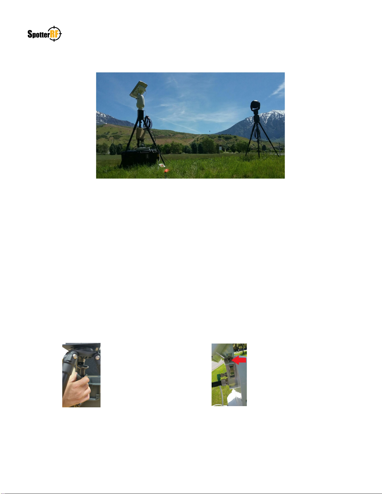
Physical Setup
The 3D Rotating Radar System will come in a Pelican Air case with all necessary equipment for setup and a Quickstart
guide that is printed for reference. Quickstart guides can also be found on the SpotterRF Partner Portal. Mount the motor
base to the tripod and secure mount with accompanied nut (See image below). Mount radar to the motor’s alignment studs
and secure the mount with the two latches on each side (See image below). Connect the short GTC and GPS cables to the
radar and motor. Mount radar, motor, and base to the ball mount on the top of the tripod using the quick release plate.
Adjust the position of the radar using the ball adjustments. Hang the HUB5 from the carabiner with cable connections
facing down. Connect GTC cables as described on Networking page of Quickstart guide.
NETWORKEDIO FIRMWARE CONFIGURATION AND SETUP V4.0
©2019 SPOTTERRF 06.18.2019 REV001 SpotterRF Technical Support | 801.742.5849 x4 | suppor[email protected] 4
3D Rotating Radar System Setup
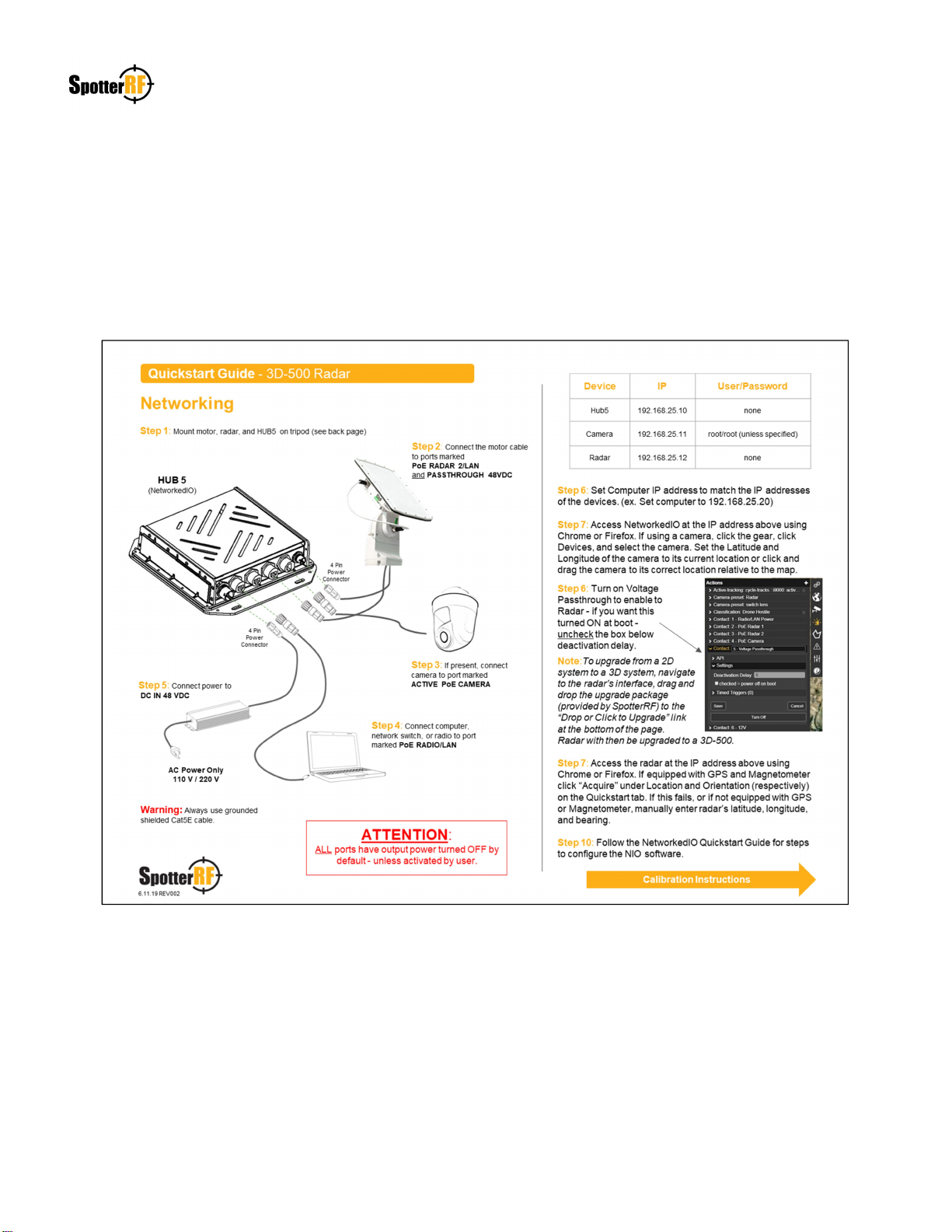
Networking
The 3D Rotating Radar System has an accompanied Quickstart guide for use in Networking configuration and setup (See
example image below). Follow steps as shown and ensure all physical networking connections are secured to their
respective devices.

NETWORKEDIO FIRMWARE CONFIGURATION AND SETUP V4.0
©2019 SPOTTERRF 06.18.2019 REV001 SpotterRF Technical Support | 801.742.5849 x4 | suppor[email protected] 5
3D Rotating Radar System Configuration
NetworkedIO (HUB5)
The 3D Rotating Radar System comes with the HUB5 NetworkedIO device. The HUB5 has ability to enable/disable
passive PoE connections within the following ports: PoE RADIO/LAN, PoE RADAR 1/LAN, and PoE RADAR 2/LAN.
These ports are still able to maintain data connection even when PoE is disabled. The ACTIVE PoE CAMERA port also
can be toggled on and off from the NIO’s interface, but data connection is not enabled while power is off on the port. The
PASSTHROUGH 24 – 48 VDC port is activated within the NIO’s interface and is needed to supply power to the rotating
motor on the system. There is also a DC OUT 12 VDC port that can be activated and its use is for future SpotterRF
devices or customized customer needs.
Be aware that new systems will have all port power defaulted to Off. The NIO interface allows the user to deselect this
power option (See any picture below). Toggling the Turn ON / Turn Off interface button will display a green action alert
and this occurrence will be dependent on the “power off on boot” state selected in defining default operation of port
power (See example pictures below). The reason PoE Radar 1 action is lit green is because its expected state is to be
powered off (box is checked) and its current state is turned on. The reason the Voltage Passthrough action is not lit green
is because its expected state is to be powered on (box is unchecked) and its current state is turned on. Selected the “Turn
Off” button in both pictures below would change their current states and action commands to either turn off the green
highlight (e.g. PoE Radar 1) or turn on the green highlight (e.g. Passthrough).
This manual suits for next models
1
Table of contents
Other SpotterRF Radar manuals


