SpotterRF SP-POWER-1 User manual

Step 1 Mount the radar. See provided
Quickstart Guide SP-Mount-1 or
SP-Mount-4 for details on mounting and
install practices.
Step 3 Once the cable has been tested
and is ready for final installation, fill Radar
GTC connector with dielectric grease.
Ensure each contact/pin is heavily
covered. (Fig. 1)
Step 4 Coat contacts/pins on incoming
RJ45 with dielectric grease and connect RJ45
to GTC connector on radar. (Fig. 2)
Warning: Do not apply grease until ready
for final connection. A contaminated
connection can cause failure
Fig. 1
WARNING: All cables used must be Outdoor Rated, CAT5E, and Shielded.
Step 6 Power PoE injector and connect
network to the radar. If using a SpotterRF
power kit, connect to the port labeled
“Network” in the diagrams to the right. (If
using an Integrated Control Cabinet, see
Cabinet quickstart for Network Port locations.)
Fig. 2
Step 2 Before connecting the Radar to
PoE, ensure the Ethernet Cable being used
is tested for continuity to ground, network
connection, and power consumption.
(See Quickstart Guide SP-TESTKIT or
Youtube video for testing instructions)
Radar
Network
Network
Radar
Step 7 To access the radar UI, connect a
computer via ethernet to the Network Port. Set
your PC to “Obtain Automatically” IP settings or
DHCP.
The UI can be accessed by entering
169.254.254.254 into a web browser. Google
Chrome and Firefox are recommended.
169.254.254.254 is the default IP address for
all radars. When using the default address,
ensure that the computer is set to DHCP and
only one radar is connected. Otherwise, there
may be a network conflict between radars.
Link
Step 5 Connect radar ethernet to PoE.
If using a SpotterRF power kit, see
diagrams to the right. Connect to the port
labeled “Radar”. (If using an Integrated
Control Cabinet, refer to the cabinet
quickstart for PoE port locations.)
Wire without
writing is (+)
for PoE
Injector
Wire without
writing is (+)
for PoE
Injector
Quickstart Guide - SpotterRF Radar
SP-POWER-1
SP-POWER-4
FEDERAL COMMUNICATIONS
COMMISSION STATEMENT
This device complies with part 15 of
the FCC Rules. Operation is subject to
the following two conditions:
(1) This device may not cause harmful
interference and (2) this device must
accept any interference received,
including interference that may cause
undesired operation.
Note: This equipment has been tested
and found to comply with the limits for
a Class B digital device, pursuant to
part 15 of the FCC Rules. These limits
are designed to provide reasonable
protection against harmful
interference in a residential
installation. This equipment generates,
uses and can radiate radio frequency
energy and, if not installed and used in
accordance with the instructions, may
cause harmful interference to radio
communications. However, there is no
guarantee that interference will not
occur in a particular installation. If this
equipment does cause harmful
interference to radio or television
reception, which can be determined by
turning the equipment off and on, the
user is encouraged to try to correct the
interference by one or more of the
following measures:
--Reorient or relocate the receiving
antenna.
--Increase the separation between the
equipment and receiver.
--Connect the equipment into an outlet
on a circuit different from that to
which the receiver is connected.
--Consult the dealer or an experienced
radio/TV technician for help.
Note: This equipment complies with
FCC radiation exposure limits set forth
for an uncontrolled environment. This
equipment should be installed and
operated with minimum distance
20cm between the radiator and your
body. This transmitter must not be
co-located or operating in conjunction
with any other antenna or transmitter.
RF Exposure Information: To comply
with FCC/IC RF exposure
requirements for mobile transmitting
devices, this transmitter should only
be used or installed at locations where
there is at least 20 cm separation
distance between the antenna and all
persons.
Troubleshooting
Verify the cable from the radar
to the injector and the cable
from the injector to the
computer have solid
connections, Cables should
have been tested (Step 2
previous page) Remove
connections and reconnect
them all.
Confirm only cables
connected to the
injector/switch are one for the
radar and one for the
Laptop/PC. Remove all
others.
Confirm the computer IP is set
to DHCP.
Access the radar on
169.254.254.254 using Google
Chrome or Mozilla Firefox.
Power cycle the radar and wait
at least one minute before
trying to access
169.254.254.254 again.
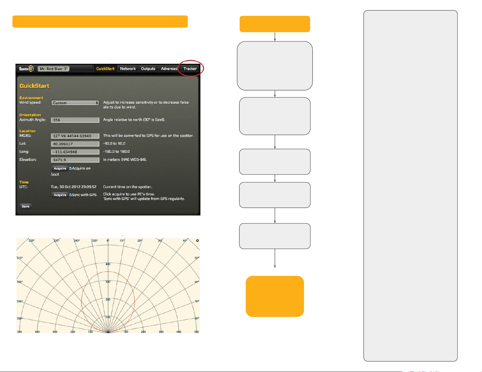
Step 9 Once the UI is visible, select the “Tracker” tab
in the top right corner.
The following page should be displayed:
Tracks from the radar will be displayed on this page in real time.
Call SpotterRF
Tech Support at
813-200-7227
Quickstart Guide - SpotterRF Radar
This manual suits for next models
1
Other SpotterRF Radar manuals


Popular Radar manuals by other brands

SOFIHUB
SOFIHUB eazense Setup and installation guide

SPOTTO
SPOTTO BLIND SPOT RADAR user guide

Smiths
Smiths Kelvin Hughes Nucleus 3 Series System handbook

Magnetrol
Magnetrol pulsar RX5 Installation and operating manual

Endress+Hauser
Endress+Hauser Levelflex FMP55 operating instructions

nanoradar
nanoradar SR-PA24R user manual

AirNav
AirNav RadarBox manual

Ametek Drexelbrook
Ametek Drexelbrook Impulse T Series Installation and operating instructions

Furuno
Furuno WR2120 Operator's manual

Endress+Hauser
Endress+Hauser micropilot S FMR 533 operating instructions

nanoradar
nanoradar NSR100W user manual

Preco
Preco PreView WorkSight for Waste w/VL ZC Quick installation guide


