SPRIANO SST77B Series User manual

OPERATING MANUAL
MN-SST77B
ED-18-01
SST77B DIFFERENTIAL PRESSURE TRANSMITTER
ORIGINAL INSTRUCTIONS

1354
EU Declaration of Conformity
TERRANOVA® Srl
Via Gramsci 1 –26827 Terranova dei Passerini (LO) –Italy
declares on his sole responsibility that the product:
SPRIANO® Electronic Transmitters series
SST70, SST71, SST72, SST75, SST76, SST77B, SST77BL, SST79B, SST70-REM
(device controlling or regulating the limits of an industrial process, like pressure, level and vacuum)
satisfies the essential requirements and conformity assessment procedures of the following legislation:
Directive 2014/34/EU (ATEX)
EU TYPE CERTIFICATE: TI 17 ATEX 304 X
Equipment for use in potentially explosive atmospheres, suitable for Zones 0, 1, 2 (process side and external side)
II 1/2G Ex db IIC T6 Ga/Gb for use in the ambient temperature range –40°C to 60°C
II 1/2G Ex db IIC T5 Ga/Gb for use in the ambient temperature range –40°C to 80°C
Presumption of conformity provided by the application of the harmonised standards:
EN 60079-0:2012+A11:2013 - EN 60079-1:2014
The Notified Body NB 1354 Technicka inspekcia a.s. performed Module D, Annex IV, Directive 2014/34/EU and
issued the Production Quality Assurance Notification. Periodical Surveillance is provided according to Annex IV,
Point 4, Directive 2014/34/EU by the same Notified Body.
Directive 2014/68/EU (PED)
EU DESIGN EXAMINATION CERTIFICATE: 1292/1/2017-2÷8
Pressure equipment, up to Category IV, for fluids (gases, liquids and vapours) in Group 1.
Conformity provided by the application of the harmonised standard:
EN 13445-1:2015, EN 13445-2:2015, EN 13445-5:2015
The Notified Body NB 1354 Technicka inspekcia a.s. performed Module H1, Directive 2014/68/EU and issued the
Production Examination Certificate. Periodical Surveillance is provided according to Directive 2014/68/EU by the
same Notified Body.
Directive 2014/30/EU (EMC)
Equipment with an adequate level of electromagnetic compatibility.
Presumption of conformity provided by the application of the harmonised standard:
EN 61326-1:2006
Terranova dei Passerini, 04/08/2017
Mr Sergio Valletti,
General Manager

OPERATING MANUAL
MN-SST77B
ED-18-01
SPRIANO® TECHNOLOGIES - www.spriano.it –spriano@terranova-instruments.com
a TERRANOVA® Srl brand - www.terranova-instruments.com - VAT IT07848810151
Factory & Sales: Via Gramsci 1 –26827 Terranova dei Passerini (LO) –Italy
Head Office: Via Rosso Medardo 16 –20159 Milano –Italy Ph: +39 0377 919119 –Fax: +39 0377 855720
Pag.3/32
1INTRODUCTION ................................................................................................................................ 4
1.1 Product Overview.......................................................................................................................... 4
1.2 Attention! ..................................................................................................................................... 4
1.3 Definitions And Symbols ................................................................................................................ 5
2DESCRIPTION.................................................................................................................................... 6
3INSTALLATION.................................................................................................................................. 7
3.1 Transmitter Identification.............................................................................................................. 7
3.2 General Mounting Requirements................................................................................................... 7
3.3 Mechanical Installation ................................................................................................................. 8
3.4 Installation For Relative Pressure Measurement ............................................................................ 9
3.5 Installation For Differential Pressure Measurement ..................................................................... 12
3.6 Electronic Head Orientation......................................................................................................... 13
3.7Electrical Connection ................................................................................................................... 14
3.8 Explosion Proof Protection........................................................................................................... 17
3.9 Earthing ...................................................................................................................................... 18
4OPERATIONS .................................................................................................................................. 20
4.1 Configuration .............................................................................................................................. 20
4.2 Keyboard Configuration .............................................................................................................. 21
5MAINTENANCE AND TROUBLESHOOTING ....................................................................................... 24
5.1 Display Error Codes ..................................................................................................................... 25
5.2 Spare Parts.................................................................................................................................. 26
6MARKING....................................................................................................................................... 27
7DATA SHEET ................................................................................................................................... 28
7.1 Functional Safety According to IEC 61508 / IEC 61511 .................................................................. 29
7.2 Main Dimensions (mm) ............................................................................................................... 30
WARNING!
Exclusively follow the instructions indicated in this document. Failure to comply
with this document may cause injury to health or may damage the equipment.
SPRIANO® TECHNOLOGIES do not takes any kind of responsibility for damages
due to failure to comply with this document.

OPERATING MANUAL
MN-SST77B
ED-18-01
SPRIANO® TECHNOLOGIES - www.spriano.it –spriano@terranova-instruments.com
a TERRANOVA® Srl brand - www.terranova-instruments.com - VAT IT07848810151
Factory & Sales: Via Gramsci 1 –26827 Terranova dei Passerini (LO) –Italy
Head Office: Via Rosso Medardo 16 –20159 Milano –Italy Ph: +39 0377 919119 –Fax: +39 0377 855720
Pag.4/32
1INTRODUCTION
1.1 PRODUCT OVERVIEW
Electronic transmitters series SST7X are apparatus which use a piezoresistive sensor for pressure
/ temperature / level measurement and transmit a current signal (4÷20 mA) proportional to the
variable measured. The series SST7X is composed by the following types:
SST70
Displacer level transmitter
SST71
Smart Float Level Transmitter
SST72
Electronic temperature transmitter
SST75
Absolute or relative pressure transmitter
SST76
Absolute or relative pressure transmitter with diaphragm
SST77B
Differential pressure transmitter
SST77BL
Level transmitter
SST79B
Immersion level transmitter
SST70-REM
4÷20mA loop powered field digital indicators (External local indicator)
MANDATORY!
The accessories used for the cable entries and to close unused shall be certificated
according to the standards EN 60079-0 and EN 60079-1 for the gas groups IIC or IIB,
according to the type of protection implemented.
1.2 ATTENTION!
This manual does not contain information concerning all type of Transmitter or all different
installation and/or working and mounting solutions. For more information or for particular
problems not considered in this manual, please address to our technical office.
The warranty period is the one contemplated in our general servicing conditions. This warranty
is neither increased nor restricted by the contents of this manual.
This Transmitter has to be installed and used only by qualified persons who have first checked
the correctness of supply voltage so that both in standard working conditions and in presence of
damages of the plant or of any part of it, no dangerous voltage can reach the Transmitter. As
the Transmitter can be utilized both with high pressure values and with aggressive media it
must be considered that an incorrect use of it could bring even serious damages to people and
things. A correct and safe working needs an adequate transport, stock and mounting other than
an appropriate maintenance service. So it is necessary for the people handling these
Transmitter to have knowledge and experience in mounting, servicing and working and to have
title to do their job with reference to “Safety Standards“.

OPERATING MANUAL
MN-SST77B
ED-18-01
SPRIANO® TECHNOLOGIES - www.spriano.it –spriano@terranova-instruments.com
a TERRANOVA® Srl brand - www.terranova-instruments.com - VAT IT07848810151
Factory & Sales: Via Gramsci 1 –26827 Terranova dei Passerini (LO) –Italy
Head Office: Via Rosso Medardo 16 –20159 Milano –Italy Ph: +39 0377 919119 –Fax: +39 0377 855720
Pag.5/32
1.3 DEFINITIONS AND SYMBOLS
In this manual are used the following symbols and labels
WARNING!
Warning label, used to warn about hazardous materials, locations, or objects,
including electric currents, poisons, and other things.
PROHIBITION!
Prohibition label, used to indicate something is not permitted.
MANDATORY!
Mandatory label, used to set obligation tasks to be performed by the user.
INFORMATION!
Information label, used to set general information for the user or warn about
hazards for the equipment.
Equipment for use in potentially explosive atmospheres
II
1/2G
Equipment Group II Category 1/2G, suitable for potentially explosive area (gases,
vapours or mists); to be installed in a separation wall between Zone 0 (process
side) and Zone 1 (external side)
Ex d
Device with Explosion Proof Enclosure
IIC
Group IIC apparatus, fit for substances of group IIC, IIB and IIA (only when used in
the ambient temperature range –40°C to 60°C)
IIB
Group IIB apparatus, fit for substances of group IIB and IIA (when used in the
ambient temperature range –40°C to 80°C)
Temperature Class of the transmitter (maximum surface temperature)
T6,
T5
only when used in the ambient temperature range –40°C to 60°C
only when used in the ambient temperature range –40°C to 80°C
Ga/Gb
Equipment to be installed in the boundary wall between an area requiring EPL Ga
and the less hazardous area

OPERATING MANUAL
MN-SST77B
ED-18-01
SPRIANO® TECHNOLOGIES - www.spriano.it –spriano@terranova-instruments.com
a TERRANOVA® Srl brand - www.terranova-instruments.com - VAT IT07848810151
Factory & Sales: Via Gramsci 1 –26827 Terranova dei Passerini (LO) –Italy
Head Office: Via Rosso Medardo 16 –20159 Milano –Italy Ph: +39 0377 919119 –Fax: +39 0377 855720
Pag.6/32
2DESCRIPTION
SST77B series SMART differential pressure transmitters are microprocessor-based instruments
that combine the analog signal advantages (4-20mA) together with the flexibility of digital
communication using HART® protocol. They can be remotely configured by a universal hand
held terminal (HHT) or by a PC with a dedicated interface.
Moreover, it is possible to locally configure the instruments (zero and span) by means of 4
pushbuttons and to display the data on the wide LCD display.
The SST77B transmitters measure differential pressure with spans from 1,2 to 20000 mbar with a
static pressure up to 200 bar. The pressure measuring element is a piezoresistive sensor. It is
possible to choose a variety of sensors to satisfy all process conditions.
The SPRIANO® measuring cell contains the sensor and transmits pressure to the electronics.
Thermal drift is compensated using the temperature signal generated by a PTC thermistor
integrated in the sensor itself. Based on these readings the microprocessor generates the 4-20
mA analog output two wires system and displays the pressure measurement on the LCD.
Some of the main characteristics of this microprocessor-based transmitter, are:
- Wide rangeability.
- Automatic temperature compensation.
- Digital communication using HART® protocol.
NOM RANGE
[mbar]
SPAN
MIN/MAX [mbar]
RANGE LIMITS
MIN/MAX [mbar]
0/18
1.2 / 36
-18 / +18
0/50
3.3 / 100
-50 / +50
0/350
23.3 / 700
-350 / +350
0/1000
66.7 / 2000
-1000 / +1000
0/2500
166.7 / 5000
-2500 / +2500
0/5000
333.3 / 10000
-5000 / +5000
0/10000
666.7 / 20000
-10000 / +10000
NOTE: Whenever an adjustment <10bar would be necessary, check if it is possible to do and create
the atmospheric reference with a dedicated tube passing inside the supply cable.
Figure 1: differential pressure transmitter SST77B
cable gland
enclosure
process connection
sensive element
(diaphragm)

OPERATING MANUAL
MN-SST77B
ED-18-01
SPRIANO® TECHNOLOGIES - www.spriano.it –spriano@terranova-instruments.com
a TERRANOVA® Srl brand - www.terranova-instruments.com - VAT IT07848810151
Factory & Sales: Via Gramsci 1 –26827 Terranova dei Passerini (LO) –Italy
Head Office: Via Rosso Medardo 16 –20159 Milano –Italy Ph: +39 0377 919119 –Fax: +39 0377 855720
Pag.7/32
3INSTALLATION
3.1 TRANSMITTER IDENTIFICATION
Transmitter data can be found on the nameplate fixed on the top of transmitter enclosure (see
MARKING). The Serial Number must be quoted at the occurrence of a specific request to the
manufacturer.
3.2 GENERAL MOUNTING REQUIREMENTS
Prior installation shall be observed following considerations:
-Check whether Transmitter’s operating conditions are within the limits as reported in the
nameplate, technical specifications sheets and/or label.
-Make sure that the operating conditions are compatible with the specification given to the
manufacturer.
MANDATORY!
-For measurement in the presence of particularly hot liquids (e.g. steam) make
sure that the Transmitter is supplied with a suitable finned arm.
-For viscous liquids or those containing solid particles in suspension make sure
that the connection to the process is a suitable one in order to avoid clogs.
WARNING!
Direct sunlight may cause serious damages to the instrument.
Never install standard Transmitter under the sun or in any other location which
could cause direct overheating through radiation.
Figure 2: mounting requirements
ZONE 1
LUCE
SOLARE
ZONE 0

OPERATING MANUAL
MN-SST77B
ED-18-01
SPRIANO® TECHNOLOGIES - www.spriano.it –spriano@terranova-instruments.com
a TERRANOVA® Srl brand - www.terranova-instruments.com - VAT IT07848810151
Factory & Sales: Via Gramsci 1 –26827 Terranova dei Passerini (LO) –Italy
Head Office: Via Rosso Medardo 16 –20159 Milano –Italy Ph: +39 0377 919119 –Fax: +39 0377 855720
Pag.8/32
3.3 MECHANICAL INSTALLATION
The Transmitter should be located, if possible, at some easily accessible, well lighted place on
the vessel or pipe, in order to allow putting in operations and maintenance work. Location
should also be such that ambient temperature at the Transmitter enclosure be not excessive
(see MARKING).
INFORMATION!
-Plant overpressure / over-temperature: observe rating plate
-Installation on seismic areas: inform technical department
-In case of unstable fluids: inform technical department
-In case of damages: inform technical department
-Inspection frequency: consideration should be given to applicable national
legislation.
WARNING!
-The process connection must be realized in such a way that guarantees the hold
at the maximum working pressure and temperature.
-Do not overcome the maximum pressure and temperatures indicated in the
technical data sheet of the selected model.
-When the device is connected to the process it can be submitted to high
pressures and temperatures. To avoid accidents subsequent to sudden discharge
of pressure and/or to contact with dangerous or flammable fluids it is necessary
to take the maximum attention when the Transmitter is taken off, heated or
repaired, verifying that it is isolated from the process and is not submitted to
pressure and/or temperature.

OPERATING MANUAL
MN-SST77B
ED-18-01
SPRIANO® TECHNOLOGIES - www.spriano.it –spriano@terranova-instruments.com
a TERRANOVA® Srl brand - www.terranova-instruments.com - VAT IT07848810151
Factory & Sales: Via Gramsci 1 –26827 Terranova dei Passerini (LO) –Italy
Head Office: Via Rosso Medardo 16 –20159 Milano –Italy Ph: +39 0377 919119 –Fax: +39 0377 855720
Pag.9/32
3.4 INSTALLATION FOR RELATIVE PRESSURE MEASUREMENT
The transmitters SST77B may be used for relative pressure measurements or level
measurements in tanks or piping. In Figure 3 the simplest mounting, direct on piping, is
illustrated.
WARNING!
-Remember to introduce always a security valve in order to put in maintenance
operations when necessary.
-When the connections are located on a vertical process line, the flow should be
upward.
INFORMATION!
Figure 3, Figure 4, Figure 5 and Figure 6 show some of the installations
recommended by ISO 2186 Standards. Refer to this Standard for more information.
Figure 3: relative pressure measurements in piping lines
FLOW
+ side
- side (ATM)
Shut off valve
OPERATING MANUAL
MN-SST77B
ED-18-01
SPRIANO® TECHNOLOGIES - www.spriano.it –spriano@terranova-instruments.com
a TERRANOVA® Srl brand - www.terranova-instruments.com - VAT IT07848810151
Factory & Sales: Via Gramsci 1 –26827 Terranova dei Passerini (LO) –Italy
Head Office: Via Rosso Medardo 16 –20159 Milano –Italy Ph: +39 0377 919119 –Fax: +39 0377 855720
Pag.10/32
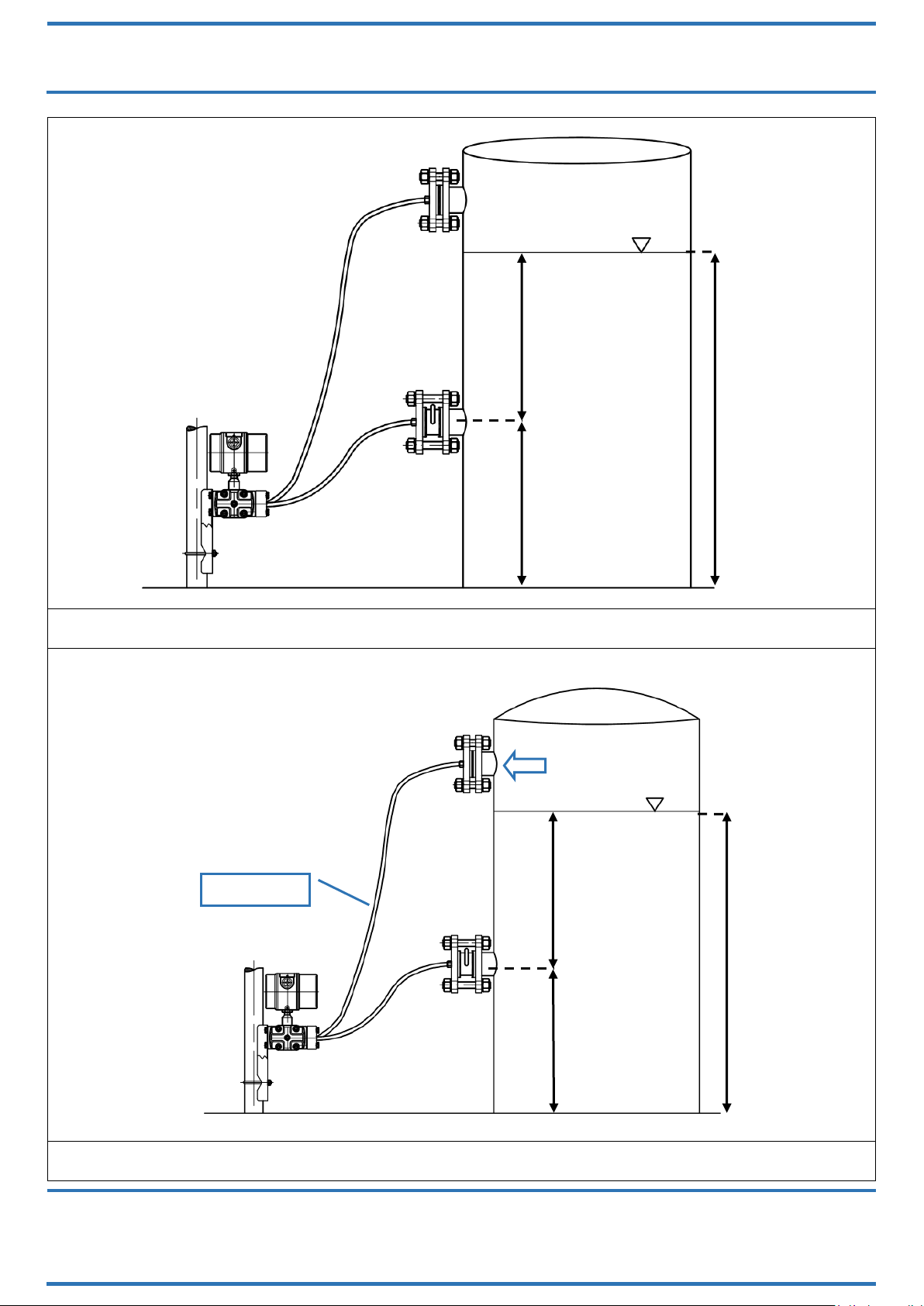
Figure 4: level measurements in open vessels
Figure 5: level measurements in closed vessels with corrosive vapors
+ side
- side
Tank
pressure
h1= Δp / ρg
h2
HTOT = h1+ h2
h2
h1= Δp / ρg
HTOT = h1+ h2
Liquid filled
+ side
- side
Normal mounting position for
the transmitter is below the
lower pressure connections.

OPERATING MANUAL
MN-SST77B
ED-18-01
SPRIANO® TECHNOLOGIES - www.spriano.it –spriano@terranova-instruments.com
a TERRANOVA® Srl brand - www.terranova-instruments.com - VAT IT07848810151
Factory & Sales: Via Gramsci 1 –26827 Terranova dei Passerini (LO) –Italy
Head Office: Via Rosso Medardo 16 –20159 Milano –Italy Ph: +39 0377 919119 –Fax: +39 0377 855720
Pag.11/32
Figure 6: level measurements in closed vessels with dry and clean vapors
INFORMATION!
-Referring to Figure 5: the descending pipes can be filled with condensate
vapors of the process fluid or with suitable inert liquid to prevent direct
contact with the transmitter diaphragm.
-Referring to Figure 6:the transmitter can be mounted above the process
connections only when in service with dry and clean gas vapors without seal
liquid.
MANDATORY!
-Pressure connections on model SST77 are marked with "H" ("+") and "L" ("-"); the
higher pressure will be applied to "+" side.
-Always check carefully all manifolds, reducers if any, vents and drain plugs for
leaks.
Tank
pressure
h1= Δp / ρg
h2
HTOT = h1+ h2

OPERATING MANUAL
MN-SST77B
ED-18-01
SPRIANO® TECHNOLOGIES - www.spriano.it –spriano@terranova-instruments.com
a TERRANOVA® Srl brand - www.terranova-instruments.com - VAT IT07848810151
Factory & Sales: Via Gramsci 1 –26827 Terranova dei Passerini (LO) –Italy
Head Office: Via Rosso Medardo 16 –20159 Milano –Italy Ph: +39 0377 919119 –Fax: +39 0377 855720
Pag.12/32
3.5 INSTALLATION FOR DIFFERENTIAL PRESSURE MEASUREMENT
Figure 7: differential pressure measurements in piping
MANDATORY!
-Always check carefully all manifolds, reducers if any, vents and drain plugs for
leaks.
FLOW
5 ways manifold
+
-
Orifice flange ORI series
Flow horifice
SST57B
OPERATING MANUAL
MN-SST77B
ED-18-01
SPRIANO® TECHNOLOGIES - www.spriano.it –spriano@terranova-instruments.com
a TERRANOVA® Srl brand - www.terranova-instruments.com - VAT IT07848810151
Factory & Sales: Via Gramsci 1 –26827 Terranova dei Passerini (LO) –Italy
Head Office: Via Rosso Medardo 16 –20159 Milano –Italy Ph: +39 0377 919119 –Fax: +39 0377 855720
Pag.13/32
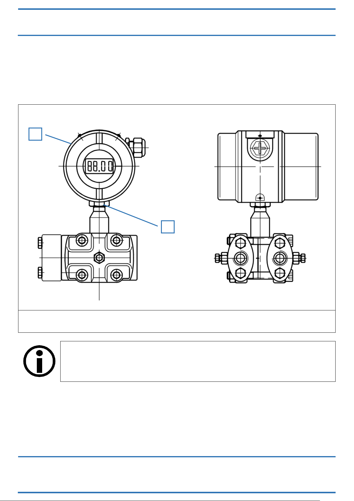
3.6 ELECTRONIC HEAD ORIENTATION
In order to rotate the electronic head in the desired position you must follow these passages
(Figure 8):
unscrew the nut (A) with key CH.24;
by hand gently rotate the enclosure (B) in the desired position;
once the desired position is reached fix the nut (A) again with the same key.
Figure 8: Rotating The Transmitter Head
INFORMATION!
It is not necessary to turn off the supply.
A
B
OPERATING MANUAL
MN-SST77B
ED-18-01
SPRIANO® TECHNOLOGIES - www.spriano.it –spriano@terranova-instruments.com
a TERRANOVA® Srl brand - www.terranova-instruments.com - VAT IT07848810151
Factory & Sales: Via Gramsci 1 –26827 Terranova dei Passerini (LO) –Italy
Head Office: Via Rosso Medardo 16 –20159 Milano –Italy Ph: +39 0377 919119 –Fax: +39 0377 855720
Pag.14/32
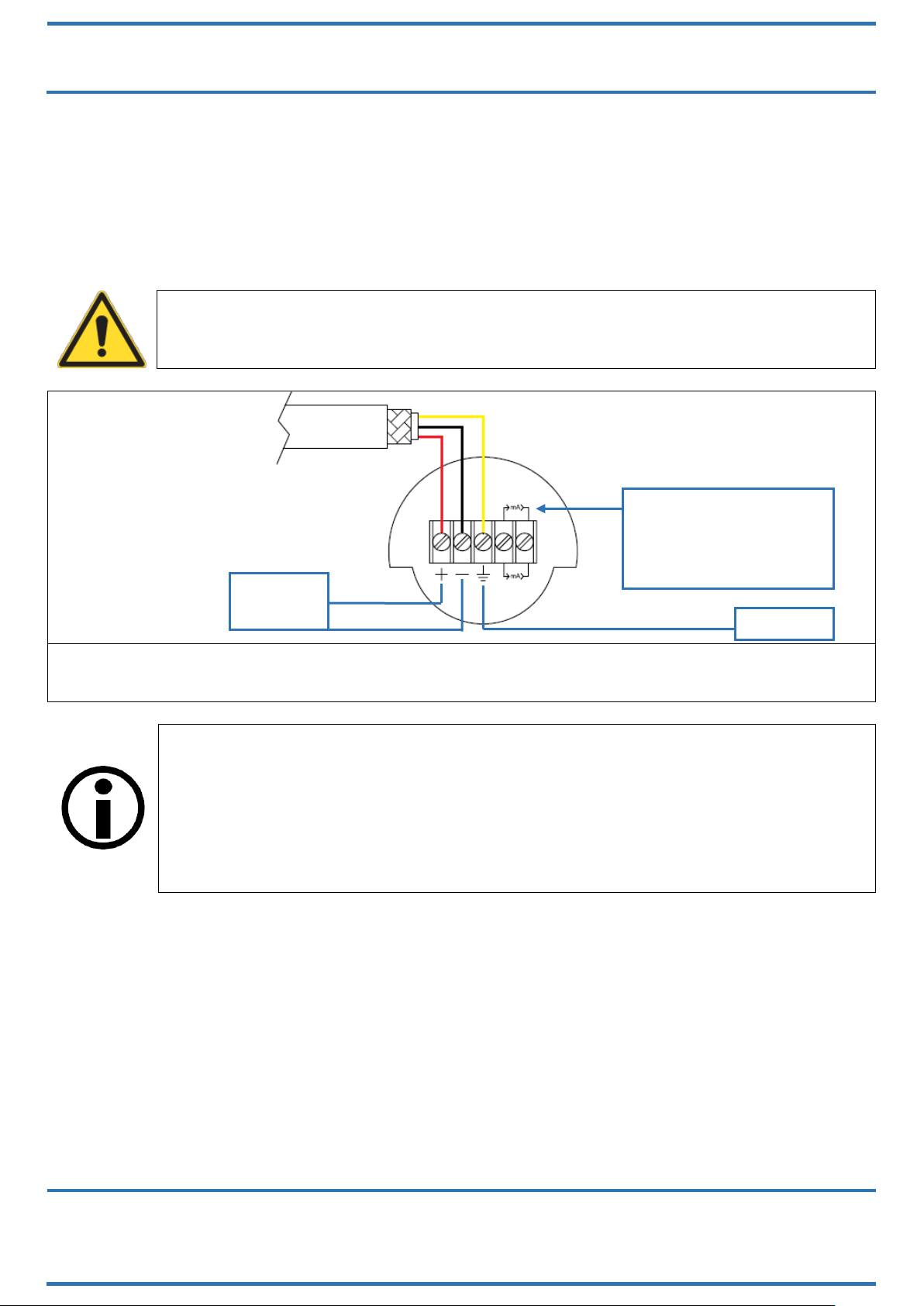
3.7 ELECTRICAL CONNECTION
Under the rear cap are placed the terminals reporting the electric polarity (Figure 9).
Insert the power supply cable into the enclosure through one of the two threaded openings.
Transmitter is protected from accidental inversion of polarity. For a better use is recommended
a twisted pair cable (22 AWG min). Avoid placing Transmitter near devices powered in AC or
Switching. Connect ground-tap of the Transmitter to the local common earth (PE) as indicated
in paragraph Earthing.
WARNING!
The threaded opening that is not used must be sealed using a suitable cap. The
caps included in the delivery are only for protection during transport.
Figure 9: electrical connection of the power cable to the terminal block
INFORMATION!
Impedance of the cables defines the possible maximum length for digital
communication. It's recommended using cable with a low impedance. The
maximum length of the point to point connection, with a load of 250 ohm and
single twisted cable 22 AWG-207 pF/m it's about 1000 meters.
The maximum connection length for the analog signal only is limited by the loads
(connected devices and cable) present in the current loop.
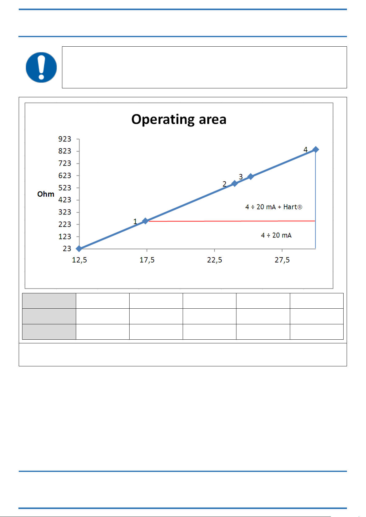
To obtain output signal of 4-20 mA, you have to determine the minimum supply voltage as a
function of the load relation: see Figure 10. From the following formula you can achieve the
right minimum value of supply voltage:
Vdc = 0.0215xRL+ 12
Where: RL= output load [Ohm].
The power supply source to assure a minimum current value of 24 mA.
Loop
4-20 mA
Loop 4-20 mA
For remote indicator
SST50-REM
(OPTIONAL)
Earthing
OPERATING MANUAL
MN-SST77B
ED-18-01
SPRIANO® TECHNOLOGIES - www.spriano.it –spriano@terranova-instruments.com
a TERRANOVA® Srl brand - www.terranova-instruments.com - VAT IT07848810151
Factory & Sales: Via Gramsci 1 –26827 Terranova dei Passerini (LO) –Italy
Head Office: Via Rosso Medardo 16 –20159 Milano –Italy Ph: +39 0377 919119 –Fax: +39 0377 855720
Pag.15/32
MANDATORY!
In order to obtain a 4÷20 mA + Hart® output a minimum load of 250 Ohm is
required.
TAG
-
1
2
3
4
Vcc
12.5
17.4
24
25.2
30
Ohm
23
250
558
615
837
Figure 10: operating area for Ex d protection
The electronic transmitters totally comply with the HART® protocol specification Revision 6.0,
so they include remote process variable interrogation, parameter setting and diagnostics.
The device is a 4÷20mA 2-wire transmitter, with FSK communication.
It is possible to read via HART® the following variables:
PV: transmitter main measure;
SV: % of the span;
TV: analog output;
QV: electronic board temperature.
Please refer to Figure 11 for the Hart® modem connection on transmitter’s 4÷20mA loop.
In Figure 12 the multidrop connection type is shown.
Vdc

OPERATING MANUAL
MN-SST77B
ED-18-01
SPRIANO® TECHNOLOGIES - www.spriano.it –spriano@terranova-instruments.com
a TERRANOVA® Srl brand - www.terranova-instruments.com - VAT IT07848810151
Factory & Sales: Via Gramsci 1 –26827 Terranova dei Passerini (LO) –Italy
Head Office: Via Rosso Medardo 16 –20159 Milano –Italy Ph: +39 0377 919119 –Fax: +39 0377 855720
Pag.16/32
It is possible to purchase the Hart Server as an additional product; this is a software including all
the interrogation, configuration and diagnostics functions required by the Hart® specifications.
Figure 11: 4÷20 mA + Hart® modem connection
Figure 12: Only HART® multidrop connection
INFORMATION!
At maximum 15 transmitters could be connected in parallel on the same line.
Attention: when more transmitters are connected on the same line the current
standing on the resistor (250-ohm) is equal to
4mA x N of connected instruments.
This could cause a high electric potential. Be sure power supply is sufficient.

OPERATING MANUAL
MN-SST77B
ED-18-01
SPRIANO® TECHNOLOGIES - www.spriano.it –spriano@terranova-instruments.com
a TERRANOVA® Srl brand - www.terranova-instruments.com - VAT IT07848810151
Factory & Sales: Via Gramsci 1 –26827 Terranova dei Passerini (LO) –Italy
Head Office: Via Rosso Medardo 16 –20159 Milano –Italy Ph: +39 0377 919119 –Fax: +39 0377 855720
Pag.17/32
Figure 13: DCS connection
MANDATORY!
Transmitter response time is <256ms.
DCS POLLING time must be set approximately at 800ms in order to avoid updating
problems both in analog and digital measurement.
On request the transmitter can be supplied in order to support a Polling time of
500ms but with a minimal consumption of 5 mA.
3.8 EXPLOSION PROOF PROTECTION
In case of use in areas with danger of explosion, it must be verified that the identified type of
transmitter fits for the classification of the zone and for the presence of flammable substances
in the plant (see MARKING).
The safety essential requisite against the risk of explosion in the classified areas are fixed from
the European Directives 2014/34/EU of 26 February 2014 (as far as it concerns the 'Equipment')
and 1999/92/EC of December 16th 1999 (as far as it concerns the 'Working Environment').
WARNING!
For the electrical connections please follow the instructions brought in this
operator manuals taking care that for the use in classified areas it is necessary to
foresee the standard EN 60079-14.
The accessories for cable entry (which must be threaded ½” NPT) must be
certified following the Standards EN 60079-Series (for Tamb >70°C must be
certified for T > 90°C).
PROHIBITION!
Do not open the covers or any part of the device in dangerous area when circuit
alive.
For explosion proof safety installation, it is mandatory to disconnect the electric
supply before opening the device.

OPERATING MANUAL
MN-SST77B
ED-18-01
SPRIANO® TECHNOLOGIES - www.spriano.it –spriano@terranova-instruments.com
a TERRANOVA® Srl brand - www.terranova-instruments.com - VAT IT07848810151
Factory & Sales: Via Gramsci 1 –26827 Terranova dei Passerini (LO) –Italy
Head Office: Via Rosso Medardo 16 –20159 Milano –Italy Ph: +39 0377 919119 –Fax: +39 0377 855720
Pag.18/32
3.9 EARTHING
WARNING!
The earth connection is required to prevent damage to people and malfunction of
the instrument.
-Case 1: Installing the instrument in a plant devoid of earthing systems
In the case where the plant devoid of earthing, it is necessary to connect the earth wire to the
terminal block through the cable that carries the signal and the power supply (Figure 9).
-Case 2: Installing the instrument in a plant provided with earthing systems
Make sure the earthing (GND) of the system has the least resistance possible.
Figure 14: 4 ÷ 20 mA loop connection with plant provided with earthing systems
You can add an additional earth wire with section not less than 4 mm2to ensure such
connection.
WARNING!
In the case represented in Figure 15, within the earth wire may also scroll through
the current protection of other instruments where the earthing of the system
(GND) had not been carried out in an optimal manner.

OPERATING MANUAL
MN-SST77B
ED-18-01
SPRIANO® TECHNOLOGIES - www.spriano.it –spriano@terranova-instruments.com
a TERRANOVA® Srl brand - www.terranova-instruments.com - VAT IT07848810151
Factory & Sales: Via Gramsci 1 –26827 Terranova dei Passerini (LO) –Italy
Head Office: Via Rosso Medardo 16 –20159 Milano –Italy Ph: +39 0377 919119 –Fax: +39 0377 855720
Pag.19/32
Figure 15: earthing in the housing
WARNING!
The hose must not be considered as a protection against electric shock for the
protection of security, but as protection against electromagnetic interference of
the instrument. Therefore, in the case of long distance cable (L> 20 m), both ends
of the braid must be connected to the chassis or to the connectors. In the case of
cables L <20 meters, will be sufficient to connect the braid only from the side
“Power Supply”.
Figure 16: earthing of the sock for cables longer than 20 meters

OPERATING MANUAL
MN-SST77B
ED-18-01
SPRIANO® TECHNOLOGIES - www.spriano.it –spriano@terranova-instruments.com
a TERRANOVA® Srl brand - www.terranova-instruments.com - VAT IT07848810151
Factory & Sales: Via Gramsci 1 –26827 Terranova dei Passerini (LO) –Italy
Head Office: Via Rosso Medardo 16 –20159 Milano –Italy Ph: +39 0377 919119 –Fax: +39 0377 855720
Pag.20/32
4OPERATIONS
Each transmitter is calibrated in factory and has on the nameplate the configuration data. If not
differently stated in the purchase order the transmitter is configured as follow:
Upper Range Value (Highest pressure value): refer to the data sheet of unit
Lower Range Value (Lower pressure value): refer to the data sheet of unit
Damping 0 sec.
4.1 CONFIGURATION
The transmitter shows the status and the measure on the dot matrix LCD (Figure 17). The span
is from -99999 to 999999.
The input signal to the transmitter can be related to the output signal in the following ways:
Direct mode = 4÷20mA output
Reverse mode = 20÷4mA output
The direct mode is obtained by setting the lower range point with the lowest value of the range
(e.g. 0.1 bar) and by setting the upper range point with the highest value (e.g. 0.5 bar). The
reverse mode is obtained by setting the lower range point with the highest value of the range
(e.g. 0.5 bar) and by setting the upper range point with the lowest value (e.g. 0.1 bar).
To display the temperature values of the sensor push the following key during transmitter
operation:
= electronic board temperature.
The unit of measure (°C) is defined in the entry TEMP UNIT in the keyboard menu (Figure 17).
Figure 17: SST77B display
5.0
▁▂▃ bar
Bar graph / % Span
Menu entering
Board temperature display
Choice bar graph / % span
Measuring unit
Displayed value
This manual suits for next models
9
Table of contents
Other SPRIANO Transmitter manuals


Popular Transmitter manuals by other brands

NCM
NCM NCM-1550-EM30 operating manual

EnOcean
EnOcean PTM 535Z user manual

NIVELCO
NIVELCO EasyTREK SP-300 Installation and programming manual

AUTEC
AUTEC Dynamic Series Original instructions

Emerson
Emerson Rosemount 702 quick start guide

Crestron
Crestron 4K DigitalMedia 8G+ DM-RX-4K-202-C Supplemental guide

M-system
M-system 10VS instruction manual

Lightware
Lightware WP-UMX-TPS-TX120-US Black quick start guide

M-system
M-system M80YS instruction manual

Broadcast Electronics
Broadcast Electronics STXe Series Technical manual

Burkert
Burkert 8138 operating instructions

Nautel
Nautel VS1 Operation and maintenance manual


