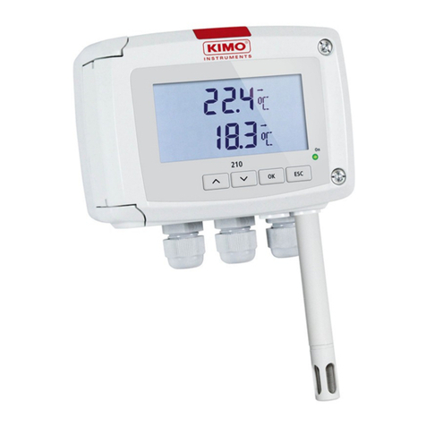
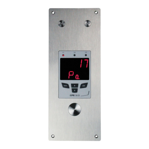
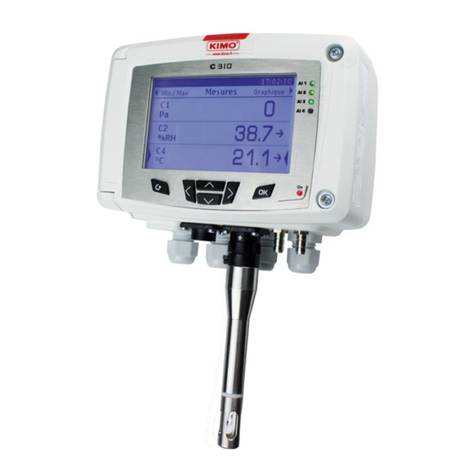
Kimo ATE 310 User manual

ATE 310 transmitters configuration by keypad


Table of contents
1. Introduction..........................................................................................................................................5
1.1. Transmitter description.................................................................................................................5
1.2. Keys description...........................................................................................................................5
2. Modbus................................................................................................................................................6
2.1. Settings........................................................................................................................................6
2.2. Functions......................................................................................................................................6
2.3. Access code to register................................................................................................................6
3. Access to the di erent unctions.........................................................................................................9
4. F 100 : Con igure the transmitter......................................................................................................10
4.1. Access to the serial number : F100...........................................................................................10
4.2. Access to the irmware version : F101.......................................................................................10
4.3. Lock the keyboard : F 140.........................................................................................................10
4.4. Modi y the security code : F141.................................................................................................10
4.5. Con igure the Modbus communication......................................................................................11
4.5.1 Con igure the slave number : F150.....................................................................................11
4.5.2 Con igure the communication speed : F151........................................................................11
4.6. Activate the options....................................................................................................................11
4.7. Activate the digital input : F180..................................................................................................11
4.8. Back to actory settings : F190..................................................................................................12
5. F 200 : Con iguration o the channels and measurement units........................................................13
5.1. Activate a channel......................................................................................................................13
5.2. Assign a measurement unit to a channel...................................................................................13
6. F 300 : analog inputs management..................................................................................................14
6.1. Set the analog inputs.................................................................................................................15
6.2. Set the ranges o analogue outputs...........................................................................................15
6.3. Measurements conversion tables..............................................................................................16
6.4. Set the decimal point position....................................................................................................16
7. F400 : Alarms management..............................................................................................................17
8. F 520 : Measurement setting............................................................................................................19
8.1. Add a coe icient.........................................................................................................................19
8.2. Add an o set..............................................................................................................................19
9. Functions recap and Modbus connections.......................................................................................20
9.1. F 100 : Con igure the transmitter...............................................................................................20
9.2. F 200 : Con igure the channels and the measurement units....................................................20
9.3. F 300 : Manage the analogue inputs.........................................................................................21
9.4. F 400 : Manage the alarms........................................................................................................21
9.5. F 500 : Set the measurement....................................................................................................23

1. Introduction
1.1. Transmitter description
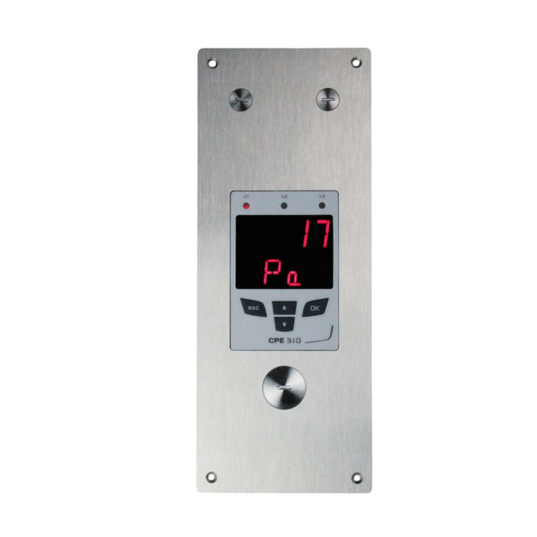
The ATE310 transmitter can be configured with the keyboard. It is possible to set the measurement units, to acti ate or not
a channel,…
Philosophy : the different settings are indicated under a folder and sub folder number form. These digital codes are
explained in details in the user manual.
1.2. Keys description
–Up key : increments a alue or a le el
–Down key : decrements a alue or a le el
–OK key : alidates the entry
–Esc key : cancels the entry or goes back to the pre ious step
Introduction 5
Up key
Down key
OK key
Esc key
10 Pa
Channel 1 indicator light Channel 3 indicator light
Channel 2 indicator light
Front access to the
mini-Din connector for a
connection on PC

2. Modbus
2.1. Settings
•Communication speed : between 2400 and 115200 bauds, 19200 bauds by default
•Data Bits : 8 bits
•Stop bit : 1 bit
•Parity : None
•low control : None
•Transmitter addressing : between 1 and 255 (always answers to requests from address 0)
•Data sending : carried out by words of 2 bytes, in the following order : high weight then low weight
2.2. Functions
•Registers reading : Function 03
•Registers writing : Function 16
•Communication loop test : Function 08
2.3. Access code to register
•Registers type
Type Size Designation ormat
U8 1 byte Unsigned integer 8 bits Byte 1
Example with a 24 (0x18) alue 0x18
Type Size Designation ormat
U16 2 bytes Unsigned integer 16 bits Byte 2 Byte 1
Example with a 300 (0x012C) alue 0x01 0x2C
Type Size Designation ormat
U32 4 bytes Unsigned integer 32 bits Byte 2 Byte 1 Byte 4 Byte 3
Example with a 1 096 861 217 (0x4160C621) alue 0xC6 0x21 0x41 0x60
Type Size Designation ormat
Real 4 bytes Real 32 bits Byte 2 Byte 1 Byte 4 Byte 3
Example with a 153.5 (0x43198000) alue 0x80 0x00 0x43 0x19
Type Size Designation ormat
Enumeration 1 byte See the Enumeration table
page 8
Idem U8
Boolean 1 byte True = 1 ; False = 0 Idem U8
6Modbus

Type Size Designation Example
Serial number 8 bytes Class (1 byte)
Range (1 byte)
Year (2 bytes)
Month (1 byte)
Number (3 bytes)
'3' (0x33)
'F' (0x46)
13 (0x000D)
8 (0x08)
98765 (0x0181CD)
ormat
Byte 2 (range) Byte 1 (class) Byte 4 (year) Byte 3 (year) Byte 6
(number)
Byte 5
(month)
Byte 8
(number)
Byte 7
(number)
0x46 0x33 0x00 0x0D 0xCD 0x08 0x01 0x81
Example with 3 13898765 : 0x0181CD08000D4633
Alarms and relays status – Modbus Code 7000
Encoded on 4 bytes (U32)
Byte 2 Byte 1
b8 – b15 b7 – b4 b3 b2 b1 b0
Unused Unused Unused Channel 3 Channel 2 Channel 1
Alarm status*
(*)1 : the channel is in alarm state / 0 : the channel is not in alarm state
Byte 4 Byte 3
b31 – b28 b27 b26 b25 b24 b23 – b20 b19 b18 b17 b16
Unused Relay 4** Relay 3** Relay 2** Relay 1** Unused Unused Alarm 3*** Alarm 2*** Alarm 1***
(**)1 : the alarm is acti ated / 0 : the alarm is deacti ated
(***)1 : the relay is triggered / 0 : the relay is not triggered
•Values (real) – Modbus code : 7010 (channel 1)
7040 (channel 2)
7070 (channel 3)
•Number of digits after the decimal point (U8) – Modbus code : 7020 (channel 1)
7050 (channel 2)
7080 (channel 3)
•Unit (U8) – Modbus code : 7030 (channel 1)
7060 (channel 2)
7090 (channel 3)
Modbus 7

List of units :
ield Unit Value
None 0
Temperature °C 16
°F 17
Hygrometry
%RH 32
g/kg 33
Kj/KG 34
°C td 35
°F td 36
°C Tw 37
°F Tw 38
Pressure
kPa 50
inWg 51
hPa 52
mbar 53
mmHg 54
mmH2O 55
daPa 56
Pa 57
Air velocity
m/s 64
fpm 65
km/h 66
Combustion ppm 112
“Enumerations” table :
Corresponding values 0 1 2 3 4 5 6 7
Modbus Communication
speed 2400 4800 9600 19200 38400 115200 Unused
Channel x Unit See units list
Channel x Transmitter None Probe 1 Module Unused
Input x Type 4 - 20 mA 0 - 20 mA 0 - 10 V 0 - 5 V 0 – 2.5 V Unused
Alarm x Mode Deacti ated Rising edge Falling edge Monitoring Unused
Alarm x Security Negati e Positi e Unused
8Modbus

3. Access to the different functions
This step is necessary for each configuration of the transmitter.
To ha e an access to the transmitter functions, and for security measures, you need to fill in a security code. By default, this
security code is 0101.
•Verify that the transmitter is powered.
➢Connect the transmitter.
➢Wait the end of the initialization phase.
➢Press OK.
“Code” is displayed with “0000”. The first 0 flashes.
➢Press OK to mo e on the second 0.
It flashes.
➢Press Up key to display 1 then press OK.
The third 0 flashes.
➢Press OK to mo e on the fourth 0.
➢Press Up key to display 1 then press OK.
The following screen appears :
“ 100” corresponds to the configuration folder number. 5 are existing :
• 100 : folder of the de ice configuration. See page 10.
• 200 : folder of the channels and measurement units. See page 13.
• 300 : folder of the analogue inputs. See page 14.
• 400 : folder of the alarms. See page 17.
• 500 : folder of the channel configuration, the integration and autozero. See page 19.
To select the required configuration folder :
“F 100” is displayed and 1 is blinking.
➢Press Up key until the required folder number displays (F 100, F 200, F 300 or F 500).
➢Press OK.
9Access to the different functions
Code
0101
F 100

4. F 100 : Configure the transmitter
This folder enables to configure the following parameters of the transmitter : security code, modbus, options and factory
configuration.
It also enables an access to the serial number and the firmware ersion of the transmitter.
4.1. Access to the serial number : F100
The serial number enables to obtain acti ation codes for the options.
F 100 is displayed (see previous page .
➢Press OK.
“F 100” displays on the screen with the serial number of the transmitter which is scrolling below.
4.2. Access to the irmware version : F101
The F100 folder is displayed.
➢Press Up key.
“F 101” displays on the screen with the version number of the firmware below. (Ex : 1.00
4.3. Lock the keyboard : F 140
For more security and a oid any handling mistake, it is possible to lock the transmitter keys.
The sub folder F101 is displayed on the screen.
➢Press Up key.
“F 140” displays on the screen with “0” meaning that the locking is deactivated.
➢Press OK.
“0” flashes.
➢Press Up or Down key, “1” is flashing then press OK.
“LOCK” displays for a few seconds then the transmitter returns to the measured values.
All the keys are inactive.
To reactivate them :
➢Press 10 seconds OK key.
“LOCK” displays for a few seconds then the transmitter returns to the display of measured values and the keys
are active again.
4.4. Modi y the security code : F141
It is possible to modify the security code.
The sub folder F140 is displayed on the screen.
➢Press Up key.
“F 141” is displayed on the screen and the security code is displayed below.
➢Press OK.
The first zero flashes.
➢Press Up or Down key to modify the digit then press OK.
The second digit flashes.
➢Press Up or Down key to modify the digit then press OK.
The third digit flashes.
➢Press Up or Down key to modify the digit then press OK.
The fourth digit flashes.
➢Press Up or Down key to modify the digit then press OK.
“OK ?” is displayed on the screen.
➢Press OK key to alidate the code modification or on Esc to cancel.
The transmitter returns to the display of the F141 folder with the new code indicated below.
10 F 100 : Configure the trans itter

4.5. Con igure the Modbus communication
4.5.1 Configure the sla e number : F150
The F141 sub folder is displayed on the screen.
➢Press Up key.
“F 150” is displayed on the screen.
➢Press OK.
“F150” flashes and the slave number is displayed below (the default number is 1 .
➢Press OK.
The first digit of the slave number flashes.
➢Press Up and Down keys to modify it then press OK.
The second digit of the slave number flashes.
➢Press Up and Down keys to modify it then press OK.
The third digit of the slave number flashes.
➢Press Up and Down keys to modify it then press OK.
“F150” flashes and the selected slave number is displayed below.
4.5.2 Configure the communication speed : F151
➢Press Up and Down keys to go to the F151 sub folder.
The communication speed in bits per second is displayed (the default communication speed is 19200 bds .
➢Press OK.
The communication speed flashes.
➢Press Up and Down keys and select the communication speed required between the following alues :
•2400 bds
•4800 bds
•9600 bds
•19.2 Kbds
•38.4 Kbds
•115.2 Kbds
➢Press OK.
“F151” flashes and the selected communication speed is displayed below.
4.6. Activate the options
To activate an option, an activation code is necessary. This code is available nearby the company
distributing the device.
Available option for the ATE310 : high resolution in pressure (sub folder 170, only for the transmitters
having the option).
- High resolution in pressure option : 170
The sub folder “F150” is displayed on the screen.
➢Press Up key.
“F170” flashes on the screen and “0” is displayed below, meaning the option is not activated.
➢Press OK.
“0” is flashing.
➢Press up key.
The transmitter asks for an activation code.
➢Enter the acti ation code (same process as the security code) then press OK.
“F170” flashes on the screen and “1” is displayed below, meaning the option is activated.
4.7. Activate the digital input : F180
The ATE310 has a digital input. This digital input must be acti ated to enable the ATE310 to communicate ia Modbus
(RS485) or Ethernet.
F 100 : Configure the trans itter 11

The “F170” sub folder is displayed on the screen.
➢Press Up key.
“F180” flashes on the screen and “OFF” is displayed below.
➢Press OK.
“OFF” is flashing.
➢Press up or down keys to display “ON” then press OK.
“F180” flashes.
4.8. Back to actory settings : F190
The “F180” sub folder is displayed on the screen.
➢Press Up key.
“F190” flashes on the screen and “RAZ” is displayed below..
➢Press OK key.
“OK?” is displayed below “F190”.
➢Press OK to confirm the factory settings or Esc to cancel.
All the performed configurations will be erased.
12 F 100 : Configure the trans itter

5. F 200 : Configuration of the channels and
measurement units
This folder allows to acti ate the channels and to configure the measurement unit for each channel.
5.1. Activate a channel
The transmitter is powered on.
➢Press OK.
➢Enter the acti ation code (see page 9).
➢Press OK.
➢Press Up key to go to the F 200 folder.
➢Press twice OK.
“ON” or “OFF” displays below “F200”.
➢Press OK.
➢Press Up and Down keys to select :
•“ON” : acti ated channel
•“O ” : deacti ated channel
➢Press OK.
The last zero of F200 flashes.
The “ 200” folder allows to acti ate the channel 1 of the transmitter.
To acti ate the channels 2 and 3 go to the following folders :
•F210 for the channel 2
•F220 for the channel 3
➢Perform the same acti ation procedure as for the channel 1.
5.2. Assign a measurement unit to a channel
The transmitter is powered on and a channel is activated.
The “F200” folder flashes.
➢Press Up key.
The “F201” sub folder is displayed with the unit corresponding to the channel 1 below.
➢Press OK.
The unit is flashing.
➢Press Up and Down keys to select the required unit.
➢Press OK.
The sign “----” indicates that the channel is deacti ated.
The “ 201” sub folder allows to select the unit of the channel 1.
To select the unit of the channels 2 and 3 go to the following folders :
•F211 for channel 2
•F221 for channel 3
➢Perform the same unit selection procedure as for the channel 1.
13 F 200 : Configuration of the channels and easure ent units

. F 300 : analog inputs management
The ATE310 ha e 3 analog inputs in standard and a digital input in option.
The following configurations are therefore possible :
1. Display of alues from a measuring system ia the analog inputs and output of the alues ia the digital output.
➢Deacti ate the digital input : “ 180” on “O ”.
The ATE310 reco ers the transmitted data by the transmitters 1, 2 and 3 ia the analog inputs and displays them. The
ATE310 can also transmit them to a computer ia the RS485 or Ethernet connection.
2. Display of alues from a measuring system (see point 1) ia the digital input
➢Acti ate the digital input : “ 180” on “ON”.
The ATE310 reco ers the transmitted data by the transmitters 1, 2 and 3 ia the digital input in RS485 or Ethernet and
displays them.
F 300 : analog inputs anage ent 14
Digital inputs Digital input/output (RS485 or Ethernet)
Transmitter 1
Transmitter 2
Transmitter 3
0-4/20 mA or 0-10 V output
Modbus network
or Ethernet
network
management
Analogue inputs Digital input/output (RS485 or Ethernet)
Transmitter 1
Transmitter 2
Transmitter 3
Modbus or
Ethernet network
management
Modbus network
or Ethernet
network
management

6.1. Set the analog inputs
The transmitter is powered on.
➢Press OK.
➢Enter the acti ation code (see page 9).
➢Press OK.
➢Press Up key to go to the F 300 folder corresponding to the analog input of the channel 1 then press twice OK.
“F300” displays with the analog input below.
➢Press OK.
The analog input flashes.
➢Press the Up or Down key to select the required input signal :
•4-20 mA
•0-20 mA
•0-10 V
•0-5 V
•0-2.5 V
➢Press OK.
The “ 300” folder corresponds to the analog input of the channel 1.
For the channels 2 and 3 go to the following folders :
•F310 for the channel 2
•F320 for the channel 3
➢Perform the same procedure as for the channel 1.
6.2. Set the ranges o analogue outputs
This function allows to modify the ranges of the analogue inputs.
The values to enter depend on measurement unit selected and not of the measurement range of the
transmitter.
Ex : the minimum and maximum ranges on a CPE310-S pressure transmitter (0 to ±100 Pa) with a reading in mmH2O must
be configured on a measurement range from 0 to ±10 mmH2O. See con ersion tables page 16.
The transmitter is powered on.
➢Press OK.
➢Fill in the acti ation code (see page 9).
➢Press OK.
➢Press Up key to go to the F 301 folder corresponding to the low scale of the channel 1.
➢Press OK.
The first digit of the minimum range flashes.
➢Enter with Up and Down keys the digit alue or the negati e sign of the alue then press OK.
The second digit flashes.
➢Enter with Up and Down keys its alue then press OK.
➢Perform the same procedure for the following digits.
➢Press OK when the last digit is configured.
F 301 flashes, the minimum range is configured.
➢Press Up key then OK key to enter in the F 302 folder corresponding to the high scale of the channel 1.
The first digit of the maximum range flashes.
➢Enter with Up and Down keys the figure of the digit or the negati e sign of the alue then press OK.
The second digit flashes.
➢Enter with Up and Down keys its alue then press OK.
➢Perform the same procedure for the following digits.
15 F 300 : analog inputs anage ent

➢Press OK when the last digit is configured.
F 302 flashes, the maximum range is configured.
To set the maximum and minimum ranges of the channel 2, go to the F 311 (minimum range) and F 312 (maximum
range) folders and follow the settings procedure of the channel 1 ranges.
To set the maximum and minimum ranges of the channel 3, go to the F 321 (minimum range) and F 322 (maximum
range) folders and follow the settings procedure of the channel 1 ranges.
6.3. Measurements conversion tables
•Pressure
Pa mmH2O InWG mbar mmHG kPa daPa hPa
±100 ±10.2 ±0.40 ±1.00 ±0.75 ±0.100 ±10.0 ±1.00
±1000 ±102.0 ±4.01 ±10.00 ±7.50 ±1.000 ±100.0 ±10.00
•Temperature
°C °
From 0.0 to +50.0 From +32.0 to +122.0
From -20.0 to +80.0 From -4.0 to +176.0
From -40.0 to +180.0 From -40.0 to +356.0
From -100.0 to +400.0 From -148.0 to +752.0
6.4. Set the decimal point position
In order to set at best maximum and minimum ranges of the inputs, it is possible to define the resolution of the
measurement to display.
The transmitter is powered on.
➢Press OK.
➢Enter the acti ation code (see page 9).
➢Press OK.
➢Press Up key to display the “ 300” folder.
➢Press twice OK then press Up key to display the “ 304” folder corresponding to the settings of the channel 1
resolution.
➢Press OK.
The number of digits after the decimal point flashes.
➢Press Up and Down keys to select the required number of digits after the decimal points : 0, 1, 2 or 3.
➢Press OK to alidate.
“F 304” flashes.
The “ 304” folder corresponds to the resolution for the channel 1.
For the channels 2 and 3 go to the following folders :
•F314 for the channel 2
•F324 for the channel 3
➢Perform the same procedure as for the channel 1.
F 300 : analog inputs anage ent 16

7. F400 : Alarms management
Three alarms modes are a ailable :
•Rising edge (1 threshold) : the alarm goes off when the measurement exceeds the threshold and stops when it
goes back below the threshold.
•alling edge (1 threshold) : the alarm goes off when the measurement goes below the threshold and stops when
it exceeds the threshold.
•Monitoring (2 thresholds) : the alarm goes off when the measurement exceeds the high threshold and is below
the predefined minimum threshold.
When an alarm goes off, it is possible to acknowledge it by pressing the OK key on the transmitter : the sound, if it is
acti ated, turns off and the displayed alue is flashing during the acknowledging (from 0 to 60 minutes). At the end of the
acknowledging duration, if the transmitter is still in alarm state, the sound is reacti ated.
It is possible to set three different alarms :
•The 400 folder corresponds to the alarm 1 setting.
•The 410 folder corresponds to the alarm 2 setting.
•The 420 folder corresponds to the alarm 3 setting.
The alarms settings procedure explained below corresponds to the alarm 1 setting. To set the alarms 2 and 3, go to the
folder corresponding to the alarm and perform the same procedure as for the alarm 1.
The transmitter is powered on.
➢Press OK.
➢Enter the acti ation code (see page 9).
➢Press OK.
➢Press Up key to go to the F 400 folder then press twice OK.
This folder is about the alarm mode.
➢Press Up or Down key to select the required alarm mode :
17 F400 : Alar s anage ent
Rising edge alling edge
Measurement (m) > Threshold (T) during time-delay T1 → Alarm acti ation.
Measurement (m) < Threshold (T) - Hysteresis (H) during time-delay T2 →
Alarm deacti ation.
Measurement (m) < Threshold (T) during time-delay T1 →
Alarm acti ation.
Measurement (m) > Threshold (S) + Hysteresis (H) during the
time-delay T2 → Alarm deacti ation.
Monitoring
The alarm goes off when the measurement is outside the maximum
and minimum threshold.

•OFF : alarm is deactivated
•1/3 : rising edge mode.
•2/3 : falling edge mode
•3/3 : monitoring mode
➢Press OK.
“F400” flashes.
➢Press Up key to go to the F401 folder of the alarm 1 (F411 for the alarm 2 and F421 for the alarm 3) then press
OK.
➢Press Up or Down key to select the channel on which the alarm will be acti ated.
➢Press OK.
“F401” flashes.
➢Press Up key to go to the F402 folder (F412 for the alarm 2 and F422 for the alarm 3) then press OK.
This folder is about the threshold 1 setting.
➢Set the threshold 1 with Up and Down keys.
➢Press OK when the last digit is set.
“F402” flashes.
➢Press Up key to go to the F403 folder (F413 for the alarm 2 and F423 for the alarm 3) then press OK.
This folder is about :
•For a rising or falling edge, this folder corresponds to the hysteresis setting.
•For a monitoring, this folder corresponds to the threshold 2 setting.
➢Set the hysteresis or the threshold 2 with the Up and Down keys.
➢Press OK when the last digit is set.
“F403” flashes.
➢Press Up key to go to the F404 folder (F414 for the alarm 2 and F424 for the alarm 3) then press OK.
This folder is about the ti e-delay 1 setting.
➢Set the time-delay 1 with Up and Down keys.
➢Press OK when the last digit is set.
“F404” flashes.
➢Press Up key to go to the F405 folder (F415 for the alarm 2 and F425 for the alarm 3) then press OK.
This folder concerns the ti e-delay 2 setting.
➢Set the time-delay 2 with Up and Down keys.
➢Press OK when the last digit is set.
“F405” flashes.
➢Press Up key to go to the F406 folder (F416 for the alarm 2 and F426 for the alarm 3) then press OK.
This folder is about the activation or not of the audible alar .
➢Set the audible alarm acti ation with Up and Down keys :
•0 : audible alarm is deactivated
•1 : audible alarm is activated
➢Press OK to alidate the alarm.
“F406” flashes.
➢Press Up key to go to the F407 folder (F417 for the alarm 2 and F427 for the alarm 3) then press OK.
This folder is about the acknowledge ent duration of the alarm.
➢Set the acknowledgement duration of the alarm with Up and Down keys.
➢Press OK when the last digit is set.
F400 : Alar s anage ent 18

8. F 520 : Measurement setting
8.1. Add a coe icient
The correction coefficient allows to adjust the transmitter according to data in pressure of the installation.
How to calculate it ? For example, the pressure in your section is 20 Pa and the transmitter indicates 18 Pa. The
coefficient to apply is 20 / 18 it means 1.111.
The transmitter is powered on.
➢Press OK.
➢Enter the acti ation code (see page 9).
➢Press OK.
➢Press Up key to go to the F 500 folder.
➢Press OK.
“F 520” flashes, corresponding to the gain setting folder for the channel 1.
➢Press twice on OK.
The first gain digit flashes.
➢Enter with Up and Down keys the number alue or the negati e sign of the alue then press OK.
The second digit flashes.
➢Enter with Up and Down keys its alue then press OK.
➢Perform the same procedure for the following digits.
➢Press OK when the last digit is configured.
F 520 flashes, the offset for the channel 1 is configured.
To add a gain to the channel 2, go to the 530 folder and perform the same procedure as for the channel 1.
To add a gain to the channel 3, go to the 540 folder and perform the same procedure as for the channel 1.
8.2. Add an o set
In order to compensate any possible drift of the transmitter, it is possible to add an offset to the alue displayed by the
transmitter by entering a alue ia the keypad.
The transmitter is powered on.
➢Press OK.
➢Enter the acti ation code (see page 9).
➢Press OK.
➢Press Up key to go to the F 500 folder.
➢Press twice the OK key then Up key to go to the F 521 folder.
“F 521” flashes, corresponding to the setting folder of the offset for the channel 1.
➢Press OK.
The first digit of the offset flashes.
➢Enter with Up and Down keys the number alue or the negati e sign of the alue then press OK.
The second digit flashes.
➢Enter its alue with Up and Down keys then press OK.
➢Perform the same procedure for the following digits.
➢Press OK when the last digit is configured.
F 521 flashes, the offset for the channel 1 is configured.
To add an offset on channel 2, go to the 531 folder and perform the same procedure as for the channel 1.
To add an offset on channel 3, go to the 541 folder and perform the same procedure as for the channel 1.
19 F 520 : Measure ent setting

9. Functions recap and Modbus connections
9.1. F 100 : Con igure the transmitter
Code Register type Modbus Description Possibilities
F 100 Real 1000 Transmitter serial number
F 101 - 1010 Firmware ersion
- U32 1020 De ice identification
- U32 1030 Probe identification
F 140 Boolean 1400 Keypad lock 0 : deacti ated
1 : acti ated
F 141 U16 1410 Security code
F 150 U8 1500 Modbus sla e number From 1 to 255
F 151 Enumeration* 1510 Modbus speed
communication
2400 / 4800 / 9600/ 19200 / 38400
/ 115200 bds
F 171 U32 - Modbus option -
F 173 - - Ethernet option -
F 180 Boolean 1800 Digital input On / Off
F 190 Boolean 1900 Restore factory
configuration
9.2. F 200 : Con igure the channels and the measurement units
Code Register type Modbus Description Possibilities
F 200 Enumeration* 2010 Channel 1 acti ation On / Off
F 201 Enumeration* 2000 Channel 1 unit selection According to the channel to
display
F 210 Enumeration* 2110 Channel 2 acti ation On / Off
F 211 Enumeration* 2100 Channel 2 unit selection According to the channel to
display
F 220 Enumeration* 2210 Channel 3 acti ation On / Off
F 221 Enumeration* 2200 Channel 3 unit selection According to the channel to
display
See Enumeration table page 8
Functions recap and Modbus connections 20
Table of contents
Other Kimo Transmitter manuals

Kimo
Kimo Class 200 User manual

Kimo
Kimo HM 50 Instruction Manual

Kimo
Kimo 210-R Series User manual

Kimo
Kimo CPE 300 User manual

Kimo
Kimo C310 User manual

Kimo
Kimo CP 111 Instruction Manual

Kimo
Kimo CA 310 User manual

Kimo
Kimo CPE 311-S User manual

Kimo
Kimo Class 300 User manual

Kimo
Kimo TG 100 Instruction Manual
Popular Transmitter manuals by other brands

Emerson
Emerson Rosemount 3051HT quick start guide

Endress+Hauser
Endress+Hauser HART iTEMP TMT142B operating instructions

RIDGID
RIDGID SeekTech ST-33Q Operator's manual

Varec
Varec 7532 Installation and operation manual

Endress+Hauser
Endress+Hauser cerabar S PMC Series operating instructions

BAPI
BAPI BA/T100 Installation & operating instructions