TESTO 6621 User manual

Instruction manual en
testo 6621 Air-conditioning transmitter for relative humidity and temperature
P2A software for testo 6621

2

Contents 3
Contents
Contents......................................................................................................3
Safety and the environment..........................................................................4
Part 1: testo 6621
Specifications ..............................................................................................5
Product description....................................................................................10
Commissioning ..........................................................................................12
Assembling the instrument ..............................................................................................12
Wiring the instrument ......................................................................................................14
Parameterizing/adjusting/analyzing the instrument ..........................................................16
Maintaining the product ............................................................................18
Tips and assistance ..................................................................................19
Part 2: testo P2A Software
Specifications ............................................................................................20
First steps ..................................................................................................21
Installing the software / driver ..........................................................................................21
Starting the software ........................................................................................................21
Product description....................................................................................22
Using the product ......................................................................................23
Tips and assistance ..................................................................................27
defresitptsvnl????

Safety and the environment4
Safety and the environment
About this document
Please read this documentation through carefully and familiarize yourself with
the product before putting it to use. Keep this documentation to hand so
that you can refer to it when necessary. Hand this documentation on to any
subsequent users of the product.
Pay particular attention to information emphasized by the following symbols:
· With the signal word Caution!:
Warns against hazards which could result in minor physical injury or damage
to equipment if the precautionary measures indicated are not taken.
· Important.
Avoiding personal injury / damage to equipment
Never store the product together with solvents and do not use any
desiccants.
Only operate the product properly, for its intended purpose and within the
parameters specified in the technical data. Do not use force.
Only carry out the maintenance and repair work that is described in the
documentation. Follow the prescribed steps when doing so. Use only OEM
spare parts from Testo.
Protecting the environment
Send the product back to Testo at the end of its useful life. We will ensure
that it is disposed of in an environmentally friendly manner.

testo 6621 - Specifications 5
PART 1: TESTO 6621
Specifications
Functions and use
The testo 6621 is a transmitter for relative humidity and temperature. In the A01
(wall/voltage output) (see identification plate), the sensors are located in the
housing; in the A02 (duct) version and the version A03 (wall/current output), the
sensors are located in a permanently connected probe shaft. The transmitter is
available with an integrated display for the reading as an option (cannot be
retrofitted by the customer).
Applications include: Air conditioning, particularly in air conditioning in buildings
and during storage. The product is not suitable for high-humidity drying
processes (relative humidity constantly over 90 %).
The transmitters must only be assembled, wired and connected by qualified
personnel.
The product must not be used in areas at risk of explosion!
defresitptsvnl????

testo 6621 - Specifications6
Ordering overview
0555 6621 Axx / Bxx / Cxx / Fxx / Gxx / Mxx / Kxx
A01 Wall version (not with B01/B05)
A02 Duct version
A03 Wall version with external probe for 4...20mA analog output (only with B01)
B01 4 - 20 mA (2-wire, 24 V DC), two analog outputs (humidity/temperature)
B02 0 - 1 V (4-wire, 24 V AC/DC), two analog outputs (humidity/temperature)
B03 0 - 5 V (4-wire, 24 V AC/DC), two analog outputs (humidity/temperature)
B04 0 - 10 V (4-wire, 24 V AC/DC), two analog outputs (humidity/temperature)
B05 4 - 20 mA (2-wire, 24 VDC), humidity: analog output, temperature: passive, Ni1000
B06 0 - 1 V (4-wire, 24 VAC/DC), humidity: analog output, temperature: passive, Ni1000
B07 0 - 5 V (4-wire, 24 VAC/DC), humidity: analog output, temperature: passive, Ni1000
B08 0 - 10 V (4-wire, 24 VAC/DC), humidity: analog output, temperature: passive, Ni1000
C00 Without display
C01 With display
E01 Housing colour light grey, with Testo-Logo (coloured)
E02 Neutral housing, white (RAL9010), without Testo-Logo
E03 Neutral housing, white (RAL9010), with Testo-Logo (black-white)
F01 Relative humidity (% RH)
G02 Temperature (°C) (only with B01 to B04)
G03 Temperature (°F) (only with B01 to B04)
M01 Sintered stainless steel filter (only for A02 and A03)
M02 Metal wire protection cap (only for A02 and A03)
M03 Sintered PTFE filter (only for A02 and A03)
M04 Open metal protection cap (only for A02 and A03)
M05 Open plastic (ABS) cap (only for A02 and A03)
K01 Language version of Instruction Manual German-English
K02 Language version of Instruction Manual French-English
K03 Language version of Instruction Manual Spanish-English
K04 Language version of Instruction Manual Italian-English
K05 Language version of Instruction Manual Dutch-English
K06 Language version of Instruction Manual Japanese-English
K07 Language version of Instruction Manual Chinese-English
Sample orders
· Duct version with 0 - 10 V outputs, with display, neutral housing without Testo-logo, % RH, °C, open plastic cap,
German/English instruction manual:
0555 6621 / A02 / B04 / C01 / E02/ F01 / G02 / M05 / K01
· Wall version with 0...5 V outputs, without display, housing colour light grey, % RH, °F, Italian/English instruction
manual:
0555 6621 / A01 / B03/ C00 / E01/ F01 / G03 / K04

testo 6621 - Specifications 7
Technical data
Parameters
· Humidity: % RH, temperature: °C/°F
Sensor
· Humidity: Testo humidity sensor, temperature: NTC
· Temperature active signal output: NTC (B01...B04)
· Temperature passive signal output: NI1000 (B05..B08)
Interfaces
· 1x mini-DIN for connecting reference measuring
instrument/PC
Measuring ranges
· Humidity: 0 - 100 % RH (> 90% RH only briefly)
· Temperature 6621-A01/A03: 0 - +60 °C/32 - 140 °F,
Temperature 6621-A02: -20 - +70 °C/-4 - +158 °F
Measuring medium/pressure range:
· Non-contaminated air (filtered air in air-conditioning
systems or air-conditioned rooms)
· Max. 1 bar positive pressure
Resolution
· Humidity: 0.1 % RH, temperature: 0.1 °C/0.1 °F
Accuracy
·Humidity*: ±2 % RH (0 - 90 % RH), ±4 % RH
(> 90 - 100 % RH)
· Temperature active : ±0.5 °C/0.9 °F
· Temperature passive, Tolerance Ni1000 temperature
sensor (B05 to B08) :
<0 °C: 0.4 °C + (0.028 x |t|)
>0 °C: 0.4 °C + (0.007 x |t|)
Other measurement-related data
· Analog outputs (2 channels each) (Order code B01 to
B04)
· Analog output 1 channel (Order code B05 to B08)
· Meas. cycle: 1/s
· Temperature coefficient (based on 25 °C):
0.05 % RH/K
· Response time t90: <15s at 2m/s
In calibration/adjustment, observe: The response time
can be considerably higher in still air.
Ambient conditions
· Operating temperature: -20 - 70 °C/-4 - 158 °F (A02),
with display from 0 - 50 °C/32 - 122 °F
· Application temperature: 0...60°C/32...140°F
(A01/A03), with display 0...50°C / 32...122°F
· Storage temperature: -40 - 70 °C/-40 - 176 °F
Analog outputs
· 0 - 1 V ±2.5 mV (4-wire)/
0 - 5V ±12.5 mV (4-wire)/
0 - 10 V ±25 mV (4-wire)/
4 - 20 mA ±0.05 mA (2-wire)
· Scaling range: -50…100°C/-58…212°F,
-50…100%RH
Voltage supply
· 2-wire (4 - 20 mA): 24 V DC ±10 %
· 4-wire (0 - 1 V/0 - 5 V/0 - 10 V): 20 - 30 V AC/V DC
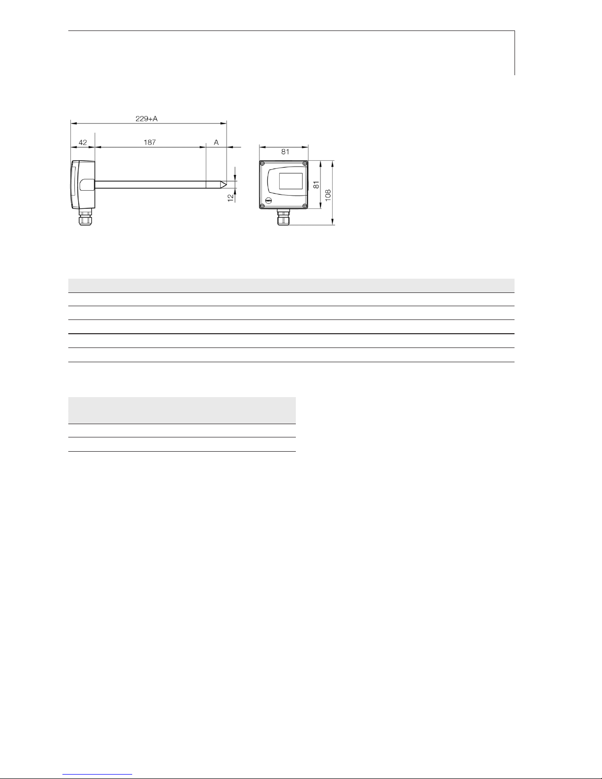
Housing
· Material: ABS
· Dimensions 6621-A01/A03: 81 x 81 x 26 mm, probe
A03 see drawing
Dimensions 6621-A02: 81 x 81 x 42 mm, see
drawing for probe
· Weight 6621-A01: 80 g,
Weight 6621-A02: 160 g
Weight 6621-A03: 90g
· Protection class 6621-A01/6621-A03: IP30,
Protection class 6621-A02: IP65 (with closed cable
screw fitting and connection socket sealed with
rubber plug, or with USB adapter attached)
· Cable couplings 6621-A02: 1 x M16 x 1.5
Display (optional)
· 2-line LCD
Directives, standards and tests
· EC Directive: 2004/108/EEC
Guarantee
· Duration: 2 years, warranty conditions see webpage
www.testo.com/warranty
* The determination of the measurement uncertainty
takes place according to GUM (Guide to the
Expression of Uncertainty in Measurement).
In the determination, the accuracy of the measuring
instrument (hysteresis, linearity, reproduceability), the
uncertainty contribution of the test site as well as the
uncertainty of the adjustment site/works calibration
are taken into account. For this purpose, k=2 of the
extension factor, the usual value in measurement
technology, is used as a basis, corresponding to a
trust level of 95%.
defresitptsvnl????

testo 6621 - Specifications8
Dimensions
testo 6621-A01 (wall):
testo 6601-A03 (wall/current version):
81
26 81
30
30
30
77,5
O 3

testo 6621 - Product description 9
testo 6621-A02 (duct):
A = length of sensor protection cap used
Sensor protection cap Order code Length A in mm
Sintered stainless steel filter M 01 33
Wire mesh filter M 02 40.3
Sintered PTFE filter M 03 35
Metal protection cap (open) M 04 35
Plastic protection cap (open) M 05 25
Choice of filter dependent on exposure to particles:
Velocity Exposure to particles
none fine coarse
< 7 m/s M04/05 M02 M03
> 7 m/s M 01 M02* M01*
* also use condensation protection 0554 0166, serves as flow protection
defresitptsvnl????

testo 6621 - Commissioning10
Product description
At a glance: testo 6621-A01 (wall/voltage version)
Top part of housing, display (option,
cannot be retrofitted) for displaying
readings:
1st line Relative humidity (duct 1),
2nd line Temperature (duct 2).
Mini-DIN port.
Opening for feeding cable through from
underneath, predetermined breaking
point in housing wall
At a glance: testo 6621-A03 (wall/curent version)
Housing cover, display (option, not
retrofittable) for measurement value
display:
1 line relative humidity (channel 1),
2 line temperature (channel 2).
Mini-DIN-connection socket.
Opening for cable inertion from below,
break-out point in housing wall.
Probe shaft
Sensor protection cap

testo 6621 - Commissioning 11
At a glance: testo 6621-A02 (duct)
Top part of housing, display (option,
cannot be retrofitted) for displaying
readings:
1st line Relative humidity (duct 1),
2nd line Temperature (duct 2).
Mini-DIN port, protected by rubber plug.
Probe shaft.
Sensor protection cap.
Cable coupling for feeding cable through.
4 screws (Phillips) for fastening the top
part of the housing.
defresitptsvnl????

testo 6621 - Commissioning12
Commissioning
Assembling the instrument
Assembling
the
testo 6621-AA01/03
(wall):
Please note that assembling the instrument on poorly insulated exterior walls
will result in humidity and temperature readings that do not reflect the
average values in the room. It is recommended that the instrument be
installed on well insulated exterior or interior walls.
1To open the housing (no connector may be inserted in the mini-DIN
socket): lift up the upper part of the housing () and remove ().
2Guide the cable from behind () or underneath (, detach pre-punched
area of the housing) into the lower part of the housing.
3Depending on the conditions in situ: Fasten lower part of housing at the
slots () using appropriate screws (not supplied).
4After wiring (see chapter Wiring the instrument): Replace the upper part of
the housing.

testo 6621 - Commissioning 13
Assembling
the
testo 6621-AA02
(duct):
1Assemble the instrument according to the conditions in situ.
The illustration below shows the instrument assembled on a duct with the
wall/duct holder (accessory, 0554 6651) as an example:
The illustration below shows the instrument assembled on a wall with the
wall/duct holder (accessory, 0554 6651) as an example:
testo 6621-A02 (duct).
Probe shaft.
Wall/duct holder (accessory 0554 6651),
for assembly on wall with spacer.
Fastening screws (customer-specific, not
included).
Locking screw for fastening the probe
shaft.
defresitptsvnl????

testo 6621 - Commissioning14
2To open the housing: Loosen the 4 screws in the upper part of the
housing () and remove the upper part of the housing ().
3Guide the cable through the cable coupling () into the lower part of the
housing.
4After wiring (see below): Close the cable coupling to fix the cable (right-
handed thread) and replace upper part of housing.
Wiring the instrument
Make sure when routing the cables that there is space between the
signal lines and interfering external lines.
If electromagnetic interference is likely, use a shielded and/or twisted
cable. The shield must be connected to earth on the side facing away
from the transmitter. Recommendation: 8-wire line with a tightly plaited
shield, wire cross-section of 0.25 - 0.5 mm².
If overvoltages are likely, install overvoltage protection devices.
Wire the instrument according to the application in hand:
2-wire/4-wire technology (2 analog outputs active)
testo 6621
(wall)
View of wiring side (rear of housing)
Voltage output A01 (4-wire,
0 - 1 V/0 - 5 V/0 - 10 V):
U = 20 - 30 VDC/AC
Current output A03
(2-wire, 4...20 mA),
max. load 500 Ω
123456
+-+-+- UrHT
6543
+
-+-rH
T
+
-U
➋
123456

testo 6621 - Maintaining the product 15
testo
6621-AA02
(duct)
View of wiring side
Voltage output (4-wire,
0 - 1 V/0 - 5 V/0 - 10 V):
U = 20 - 30 VAC/DC
Current output (2-wire,
4 - 20 mA), max. load 500 Ω
2-wire/4-wire technology (1 analog output active for humidity,
1 passive temperature signal output)
testo
6621-AA01
(wall)
View of wiring side (rear of housing)
Voltage output A01 (4-wire,
0...1V/0...5V/0...10V):
U = 20...30VDC/AC,
Temperature signal output
Ni1000 passive
testo
6621-AA02
(duct)
View of wiring side
Voltage output (4-wire,
0...1V/0...5V/0...10V):
U = 20...30VAC/DC,
Temperature signal output
Ni1000 passive
Current output (2-wire,
4...20mA), max. load 500Ω,
Temperature signal output
Ni1000 passive
654321
+-+-+- T
rH
U
6543
+-
T
+
-
U
+-
U
➋
+-
rH
123456
+-+-+- UrH
T
654321
+-+-+- T
rH
U
6543
+-+-
rH T
+
-
U
+-
U
defresitptsvnl????

testo 6621 - Tips and assistance16
3-conductor technology (2 analog outputs active)
All earth connections are connected to each other (= one common earth).
Attention! Incorrect polarity wil destroy the instrument (instrument not reverse
polarity-proof).
Connections for voltage supply: connect common earht to pin 2!
testo
6621-AA01
(Wall)
View of wiring side (rear of housing)
testo
6621-AA02
(Duct)
View of wiring side
123456
+-
+-
+-
UrH T
~
24V~
123456
+-+
-
+- UrHT
-+

testo P2A Software - Specifications 17
Parameterizing/adjusting/analyzing the
instrument
The analog outputs can be scaled in the following ranges, beyond the
measurement range of the measurement transmitter: -50…100°C /
-58…212°F, -50…100%RH.
The instrument is parameterized, adjusted and analyzed using the P2A
Software, see “Part 2: testo P2A Software”.
Alternatively, the 1-point adjustment can be carried out using the adapter
(accessory, 0554 6022) and a testo 400/650 with reference humidity probe.
1-point adjustment with adapter
1Connect testo 400/650, with
reference humidity probe
(0636 9741) connected, to the
interface of the testo 6621 via the
adapter (connected to probe socket
1 of the testo 400/650).
2Expose the testo 6621 and the
reference humidity probe to the
same reference conditions (e.g. in
the humidity generator) and allow
climatic conditions to equalize.
3Switch on the testo 400/650. The values of the testo 6621 and reference
humidity probe are displayed on the left and right-hand sides of the two-
part display of the testo 400/650 respectively.
4Adjust the humidity and temperature values on the reference humidity
probe using the Probe > Probe Adjustment menu item on the testo 400/650.
5Disconnect the adapter from the interface of the testo 6621.
defresitptsvnl????

testo P2A Software - First steps18
Maintaining the product
Cleaning
the
housing:
Clean the housing with a damp cloth (soap suds) if it is dirty. Do not use
aggressive cleaning agents or solvents!
Cleaning
the
sensor
of
the
testo 6621-AA01
(wall/voltage
version):
Do not touch sensor.
Open the housing and carefully clean the reflective surface of the sensor
(top right, assembled vertically on the circuit board) with distilled water or
ethanol. Allow the sensor to dry completely.
Cleaning
the
sensor
of
the
testo 6621-AA02
(duct),
testo
6621-AA03
(wall/current
version):
Do not touch sensor.
Unscrew the sensor protection cap and carefully rinse the reflective
surface of the sensor with distilled water or ethanol. Allow the sensor to
dry completely.
Cleaning
the
filter
of
the
testo 6621-AA02
(duct),
testo
6621-AA03
(wall/current
version):
If using a sintered filter:
Clean regularly by blowing out with compressed air or ultrasonic bath,
depending on the level of contamination created by the process.

testo P2A Software - Product description 19
Tips and assistance
Questions and answers
Question Possible causes / solutions
Signal response too slow. · Clean the filter
If we could not answer your question, please contact your dealer or Testo
Customer Service. For contact data, see back of this document or web page
www.testo.com/service-contact.
Accessories and spare parts
Designation Article no.
Parameterizing, adjusting and analyzing software (P2A Software incl. adapter cable for USB to mini-DIN) 0554 6020
Adapter (for 1-point adjustment with testo 400/650) 0554 6022
Control and adjustment set for 2-point adjustment (11.3 % and 75.3 % RH), only for testo 6621 - A02 0554 0660
Wall/duct holder 0554 6651
Replacement sensors (% RH) for testo 6621-A02 0420 0023
External display, testo 54-2AC; 2 switching outputs (up to 300 V AC), 230 V AC, for one measurement channel 5400 7553
Process display testo 54-7AC, 2 switching outputs and RS 485, 230 V AC, for one measurement channel 5400 7555
Mains unit (bench unit), 110 - 240 V AC/24 V DC (350mA) 0554 1748
Mains unit (top-hat rail mounting), 90 - 264 V AC/24 V DC (2.5A) 0554 1749
ISO calibration certificate for humidity at 11.3% and 75.3% RH 0520 0076
ISO-calibration certificate humidity 0520 0176
Sintered stainless steel filter 0554 0647
Wire mesh filter 0554 0757
Sintered PTFE filter 0554 0759
Metal protection cap (open) 0554 0755
Plastic protection cap (open) 0192 0265
Reference set (testo 650, 1 %RH probe with certificate) 0699 3556/20
For a complete list of all accessories and spare parts, please refer to the
product catalogues and brochures or look up our website at: www.testo.com
defresitptsvnl????

testo P2A Software - Product description20
PART 2: TESTO P2A SOFTWARE
Specifications
Functions and use
The testo P2A Software (0554 6020) is parameterizing, adjusting and analyzing
software for Testo transmitters. It is not supplied with the testo 6621.
System requirements
Operating system
· Windows 2000 SP4, Windows XP or Windows Vista
Computer
· Pentium processor of at least 400 MHz or equivalent
· 128 MB RAM
· Graphics resolution of at least 1,024 x 768
· Unused hard drive capacity of at least 15 MB
· CD-ROM drive
· USB interface or corresponding adapter
Table of contents
Other TESTO Transmitter manuals
Popular Transmitter manuals by other brands

Nautel
Nautel VS300 troubleshooting manual

Baker Hughes
Baker Hughes Panametrics DigitalFlow XGM868i Startup guide

Dwyer Instruments
Dwyer Instruments AVUL Series Installation and operating instructions

ABB
ABB STT04 instruction manual

LEYBOLD
LEYBOLD THERMOVAC TTR 91 N operating manual

Johnson Controls
Johnson Controls GS3000 installation guide