Sprint Fitness RACER 2 User manual


2
Dear Customer,
Thank you for purchasing the Sprint-RACER 2 indoor cycle. lease read
these instructions very carefully before using this item, as they include
important information regarding the safety, installation, maintenance
and use of your indoor cycle.
Please note the following precautions before assembling or
operating the machine.
1. Keep children and pets away from the indoor cycle at all times. DO NOT leave
unattended children in the same room with the machine.
2. If the user experiences dizziness, nausea, chest pain, or any other abnormal
symptoms, STO the workout at once. CONSULT A HYSICIAN IMMEDIATELY.
3. Before beginning training, remove all objects within a radius of 2 meters of the
machine. DO NOT place any sharp objects around the Indoor cycle.
4. osition the indoor cycle on a clear, level surface away from water and moisture.
lace a mat under the unit to help keep the machine stable and to protect the
floor.
5. Use the Indoor cycle only for its intended use as described in this manual. DO
NOT use any other accessories unless recommended by the manufacturer.
6. Assemble the machine exactly as per the instructions in this manual.
7. Check all bolts and other connections before using the machine for the first time
and ensure that the cycle is in a safe condition.
8. erform routine inspections of the equipment. ay special attention to
components which are the most susceptible to wear i.e. connecting points and
wheels. Any defective components should be replaced immediately to maintain
safe operation. lease DO NOT use the indoor cycle until it is repaired.
9. NEVER operate the indoor cycle if it is not functioning properly.
10. This machine should only be used by one person at a time.

3
11. Do not use abrasive cleaning products to clean the machine. Remove drops of
sweat from the machine immediately after each training session.
12. Always wear appropriate workout clothing when exercising. Running or aerobic
shoes are also advisable.
13. Before exercising, always perform stretching first, to avoid injury.
14. The power of the machine increases with increasing the speed, and the reverse.
The machine is equipped with an adjustable knob, which can adjust the
resistance.
WARNING: BEF RE BEGINNING THIS R ANY EXERCISE PR GRAM,
C NSULT Y UR PHYSICIAN FIRST. THIS IS ESPECIALLY IMP RTANT F R
INDIVIDUALS VER THE AGE F 35 R TH SE WITH PRE-EXISTING
HEALTH PR BLEMS. READ ALL INSTRUCTI NS BEF RE USING THE
IND R CYCLE. SPRINT FITNESS ASSUMES N RESP NSIBILITY F R
PERS NAL INJURY R PR PERTY DAMAGE SUSTAINED BY R
THR UGH THE USE F THIS PR DUCT
4
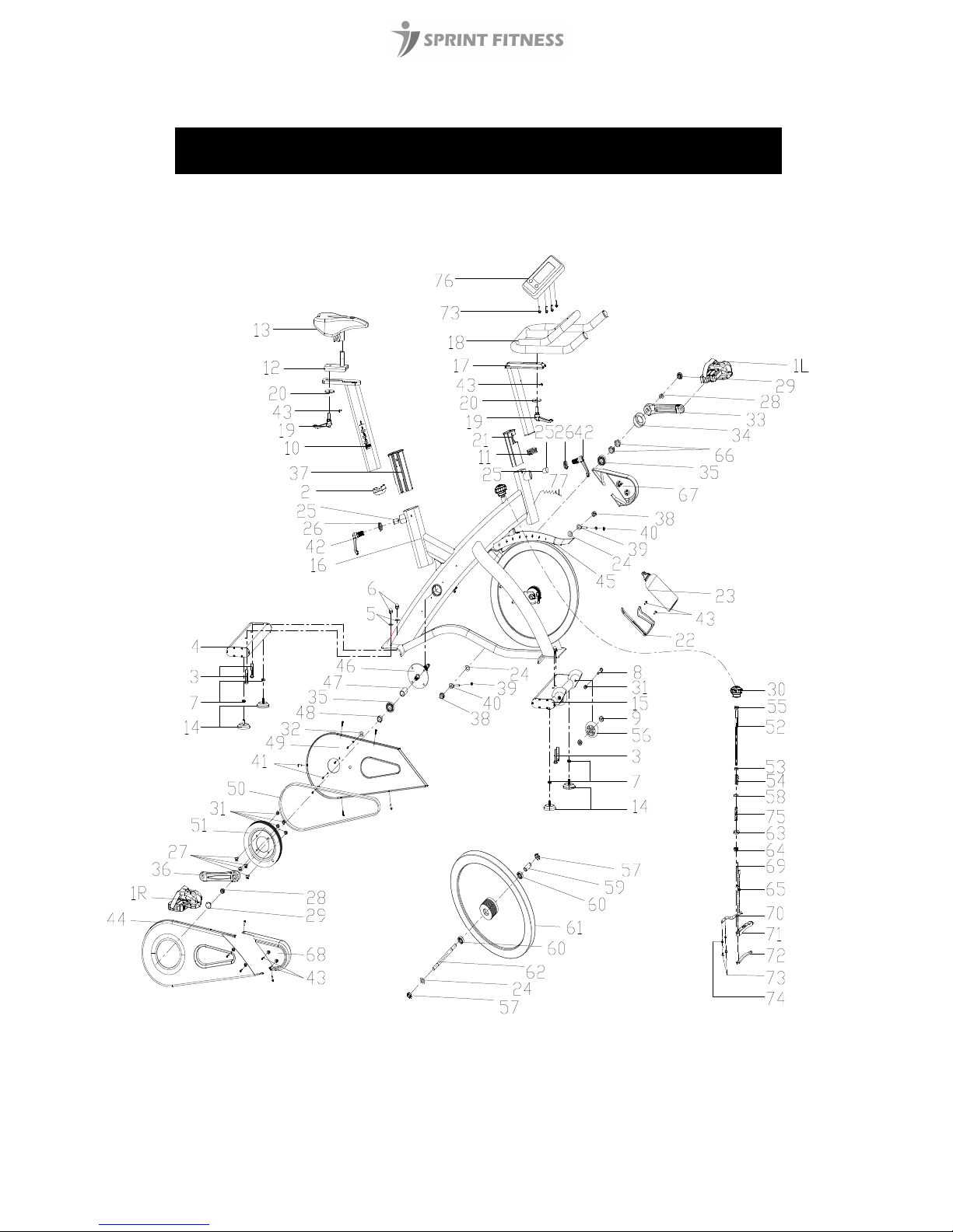
EXPLODED-VIEW & PARTS LIST

5
NO NAME
QUANTITY SPEC
1 PEDAL 1 JD-304(M18*1.5)
2 END CAP1 1 70*30*1.5
3 BOLT 1 4 GB/T 12-1988 M10*55
4 REAR STABILIZER 1 WELDING
5 FLAT WASHER 4 GB/T 95-2002 10
6 NUT 4 GB/T 802-1988 M10
7 NUT 4 GB/T 41-2000 M8
8 BOLT 2 2 GB/T 5780-2000 M8*40
9 BEARING 4 608ZZ
10 VERTICAL SEAT POST 1 WELDING
11 END CAP 2 1 38*38*1.5
12 SEAT POST 1 WELDING
13 SEAT 1 DD-2681
14 STOPPER 4 φ60*36/(M8X25)
15 FRONT STABILIZER 1 WELDING
16 MAIN FRAME 1 WELDING
17 HANDLEBAR POST 1 WELDING
18 HANDLE BAR 1 WELDING
19 L SHAPE KNOB 2 M10*25
20 FLAT WASHER 1 2 φ45*φ10.5*5
21 PLASTIC SLEEVE 1 38*38*1.5
22 B0TTLE HOLDER 1 φ6
23 B0TTLE 1 φ73*215
24 FLAT WASHER 3 GB/T 95-2002 12
25 FIXING SHAFT 2 φ22*23 (口)
26 FIXING NUT 2 Q235/32*12
27 BOLT 1 4 GB/T 70.2-2000 M8*15
28 NUT 2 M12X1.25 H=8MM
29 CRANK END CAP 2 φ28*6.5
30 KNOB 1 φ60*43
31 NUT 6 GB/T 889.1-2000 M8
32 PLASTIC RING 4 φ20*φ9*3
33 LEFT CRANK 1 170*15
34 CRANK COVER 1 φ56*28
35 BEARING 2 6004ZZ
36 RIGHT CRANK 1 170*15
37 PLASTIC SLEEVE 1 1 70*30*1.5

6
NO NAME
QUANTITY SPEC
38 NUT 2 M12X1.25
39 FIXING BOLT 2 M6*54
40 NUT 2 GB/T 889.1-2000 M6
41 BOLT 6 13 GB/T 845-1985 ST4.2*19
42 L SHAPE KNOB 2 M16*25 (M16*1.5)
43 SCREW 3 7 GB/845-85 ST4.8X13
44 OUTER COVER 1 612*282*46.6(451g)
45 FLYWHEEL COVER 1 414*79*89(102g)
46 AXIS 1 φ20*162
47 LONG FIXING TUBE 1 φ25*φ20.5*41
48 SHORT FIXING TUBE 1 φ25*φ20.5*12
49 INNER COVER 1 608*280*21(421g)
50 BELT 1 5PK56
51 BELT WHEEL 1 φ200*24
52 Brake knob rod 1 φ10X230
53 BUSHING 1 φ18*φ10*10
54 SPRING 1 1 δ1.8X40
55 NUT 1GB/T 889.1-2000 M10
56 PU WHEEL 2 φ69*23
57 NUT 2 M12X1.25 H=6
58 FIXING NUT 2 1 16X16X5 (M10)
59 FIXING TUBE 1 φ16*φ12.1*35
60 BEARING 2 6001ZZ
61 FLYWHEEL 1 φ453*29 (20KG)
62 FLYWHEEL SHAFT 1 φ12*160
63 FLAT WASHER 2 1 Ф10.2
64 DOMED NUT 1 GB/T 802-1988 M10
65 FLAT WASHER 1 2 GB/T 95-2002 6
66 FIXING NUT 2 27*M20*1(5mm)
67 LEFT FLYWHEEL COVER 1 240.6*128.6*62(118g)
68 RIGHT FIYWHEEL COVER 1 258.7*131.8*62(97g)
69 BOLT 8 2 GB/T 70.1-2000 M6*12
70 ADJUSTING METAL 1
δ1.5
71 BLOCK 1 161*21*19
72 WOOLLY BLOCK 1 156*15.5*10
73 BOLT 9 2 GB/T 5780-2000 M5*10
74 SPRING WASHER 1 2 GB/T 859-1987 5
75 SPRING 2 1 φ1.0X55
76 COMOUTER 1 ST-6521
77 SENSOR 1 SR-202

7
FIG.1
ASSEMBLY INSTRUCTIONS
1. PREPARATI N:
A. Before assembly, make sure that you have enough space around the item.
B. Use the tools included for assembly.
C. Before assembly, please check whether all required parts are available (at the top of this
instruction sheet you will find an explosion drawing with all single parts (marked with
numbers) which this item consists of.
2. ASSEMBLY:
:
FIG.2
FIG.2:
Slide the Vertical Seat ost (pt.10) into the
seat post housing on the main frame
(pt.16), then slide the Seat ost (pt.12)
into the Vertical Seat ost (pt.10). Secure
using a flat washer 1 (20) and L Shape
knob (19). Slacken the knurled section of
the L Shape Knob (pt.42), pull the knob
back and then select the desired height.
Release the knob and retighten the
knurled portion.
Now fix the Seat (pt.13) to the Seat ost
(pt.12) as shown, and tighten the bolts
around the screws under the seat.
FIG.1:
Attach the Front Stabilizer (pt.15) to the
Main Frame (pt.16) using two sets of Ø8
Flat Washers (pt.5), M10 Domed Nut (pt.6)
and M10*55 Carriage bolt (3).
Attach the Rear Stabilizer (pt.4) to the
Main Frame (pt.16) using two sets of Ø10
Flat Washers (pt.5), M10 Domed Nut (pt.6)
and M10*55 Carriage bolt (3).
Fix the bottle holder (pt.22) to the main
frame (pt.16) with the screw (pt.43) and
then slide the bottle (pt.23) into the
bottle holder (pt.22)

8
FIG.3
FIG.4
FIG.3:
Slide the Handlebar ost (pt.17) into the
handlebar post housing on the main
frame(pt.16). Slacken the knurled section of
the L Shape Knob (pt.42), pull the knob back
and then select the desired height. Release
the knob and retighten the knurled portion.
Fix the Handlebar (pt.18) with a flat washer
(20) and L Shape knob (19)
ATTENTION: FIX THE HANDLEBAR TIGHTLY
Fix the Computer (pt.76) onto the
Computer Holder with bolt (pt.73),
connect the plugs (A1&A2),
FIG.4:
The edals (pt.1 L & pt.1 R) are marked
"L" and "R" - Left and Right.
Connect them to their appropriate crank
arms. The right crank arm is on the right-
hand side of the cycle as you sit on it.
Note that the Right pedal should be
threaded on clockwise and the Left
pedal anticlockwise.
9
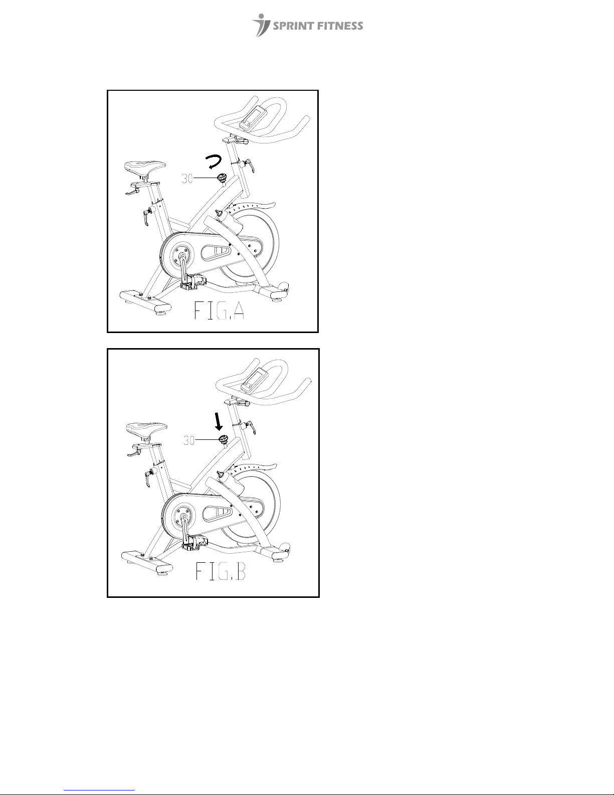
FIG A:
Adjusting the Tension:
Increasing or decreasing the tension allows
you to add variety to your workout sessions by
adjusting the resistance level of the bike.
To increase tension and increase resistance
(requiring more strength to pedal), turn the
Emergency Brake & Tension Control Knob (#30)
to the right.
To decrease tension and increase resistance
(requiring less strength to pedla), turn the
Emergency Brake & Tension Control Knob (#30)
to the left.
FIG B:
Using the Emergency Brake Function:
The same knob that allows you to adjust the
tension of the bike also doubles as the
Emergency Brake.
Use this safety feature in any situation where
you would need to get off the bike and/or
stop the bike’s flywheel.
To use the Emergency Brake function in any
situation you would need it in, firmly press
down on the Emergency Brake & Tension
Control Knob (#30).

10
ADJUSTMENT
•To adjust the seat height, slacken the spring knob on the vertical post stem on the
main frame and pull back the knob. osition the vertical seat post to the desired
height. Align holes and then release the knob and retighten it.
•To move the seat forward in the direction of the handlebar or backwards away
from it, loosen the adjusting knob and washer and pull the knob back. Slide the
horizontal seat post into the desired position. Align holes and then retighten the
adjusting knob.
•To adjust the handlebar height, slacken the spring knob and secondary knob and pull
both knobs back. Slide the handlebar post along the housing on the main frame to
the desired height and, with the holes aligned correctly, tighten the spring adjusting
knob and then the secondary knob.
MAINTENANCE
•After using the indoor cycle, always wipe down the cycle, making sure that it is
clean and dry to avoid rusting.
•At regular intervals, apply a small amount of 3 in 1 oil all around the perimeter of
the flywheel where it comes into contact with the brake. This prolongs the life of
the brake and prevents the cycle from becoming noisy in operation.
•erform routine inspections of the equipment, paying special attention to
components which are the most susceptible to wear i.e. connecting points and
wheels. Replace any defective components immediately to maintain safe
operation, and DO NOT use the indoor cycle until it is repaired.

11
EXERCISE INSTRUCTI NS
Using your IND R CYCLE provides you with several benefits, it will improve your physical
fitness, tone muscle and in conjunction with a calorie controlled diet, help you lose weight.
1. The Warm Up Phase
This stage helps get the blood flowing around the body and the muscles working properly. It
will also reduce the risk of cramp and muscle injury. It is advisable to do a few stretching
exercises as shown below. Each stretch should be held for approximately 30 seconds, do not
force or jerk your muscles into a stretch - if it hurts, ST P.
2. The Exercise Phase
This is the stage where you put the effort in. After regular use, the muscles in your legs will
become stronger. It is very important to maintain a steady tempo throughout. The rate of
work should be sufficient to raise your heart beat into the target zone shown on the graph
below.
SIDE BENDS OUTER THIGH
INNER THIGH
FORWARD
BENDS
CALF / ACHILLES
This stage should last for a minimum of 12 minutes for most people
start at about 15
-
20 minutes

12
3. The Cool Down Phase
This stage is to let your cardio-vascular system and muscles wind down. This is a repeat of
the warm up exercise e.g. reduce your tempo, continue for approximately 5 minutes. The
stretching exercises should now be repeated, again remembering not to force or jerk your
muscles into the stretch.
As you get fitter you may need to train longer and harder. It is advisable to train at least three
times a week, and if possible space your workouts evenly throughout the week.
MUSCLE T NING
To tone muscle while on your IND R CYCLE you will need to have the resistance set quite
high. This will put more strain on your leg muscles and may mean you cannot train for as
long as you would like. If you are also trying to improve your fitness you may need to alter
your training program. You should train as normal during the warm up and cool down phases,
but towards the end of the exercise phase you should increase resistance, making your legs
work harder than normal. You may have to reduce your speed to keep your heart rate in the
target zone.
WEIGHT L SS
The important factor here is the amount of effort you put in. The harder and longer you work
the more calories you will burn. Effectively this is the same as if you were training to improve
your fitness, the difference is the goal.
USE
The tension control knob allows you to alter the resistance of the pedals. A high resistance
makes it more difficult to pedal, a low resistance makes it easier. For the best results set the
tension while the bike is in use.
For further information about the Sprint Fitness range visit www.sprint-fitness.co.uk
Table of contents
Popular Exercise Bike manuals by other brands

Stages cycling
Stages cycling STaGESSOLO LES MILLS VIRTUAL BIKE SC4.21 Assembly guide

Assault Fitness
Assault Fitness Airbike Elite quick start guide

Durafit
Durafit GLIDER owner's manual

Sole Fitness
Sole Fitness SB700 Service manual

Precor
Precor 600 Series Assembly guide

BH FITNESS
BH FITNESS INERTIA H720R Instructions for assembly and use


ICON Health & Fitness
ICON Health & Fitness Pro-Form Pro TC user manual

Nautilus
Nautilus U616 Assembly manual / owner's manual

HASE
HASE Trix user manual

Renkforce
Renkforce RF-HMB-300 operating instructions

Sunny Health & Fitness
Sunny Health & Fitness UPRIGHT ROW-N-RIDE SF-A022077 user manual

HOMCOM
HOMCOM A90-301 user manual