8
operation
Operation
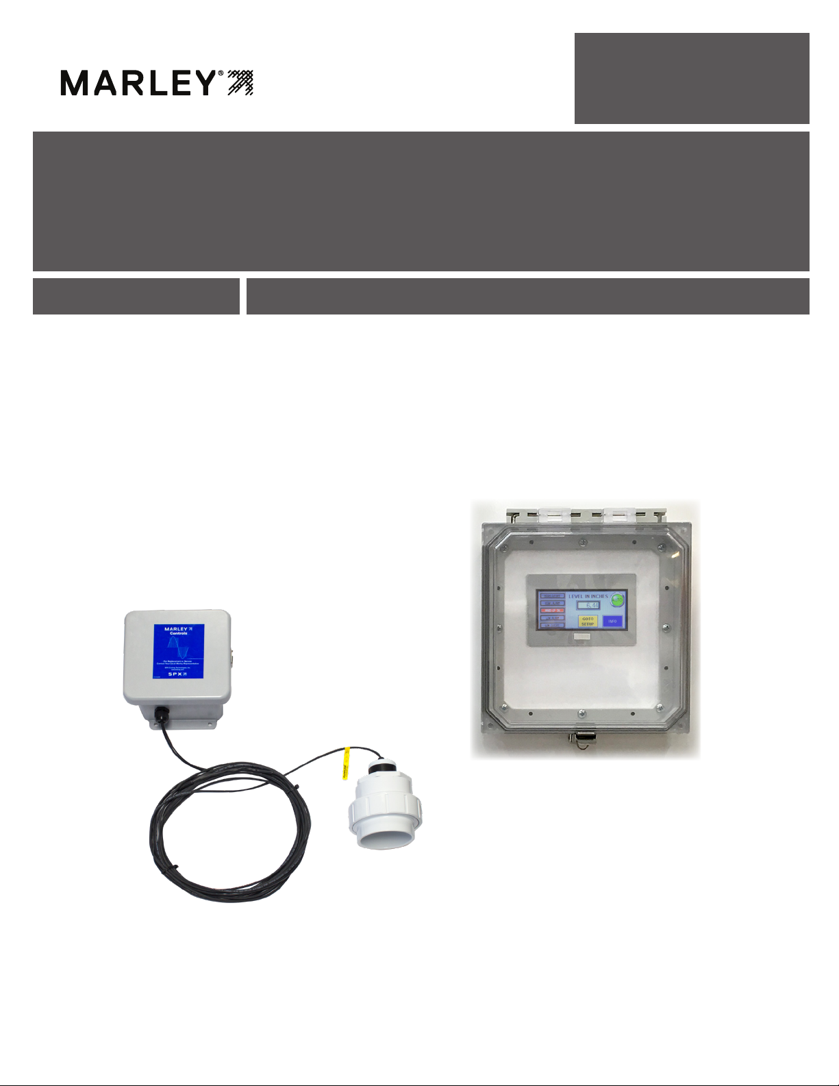
The LLC+ui water level control system consists of an ultrasonic sensor placed
to measure the water level in the cold water basin. The senor is typically located
inside the cooling tower or on some cooling towers in an external chamber. A
PLC with HMI touch screen is used to program water level heights and offers
a visual indication of the water level. Internal relays with form "C" contacts are
used as switches, one for each water setpoint.
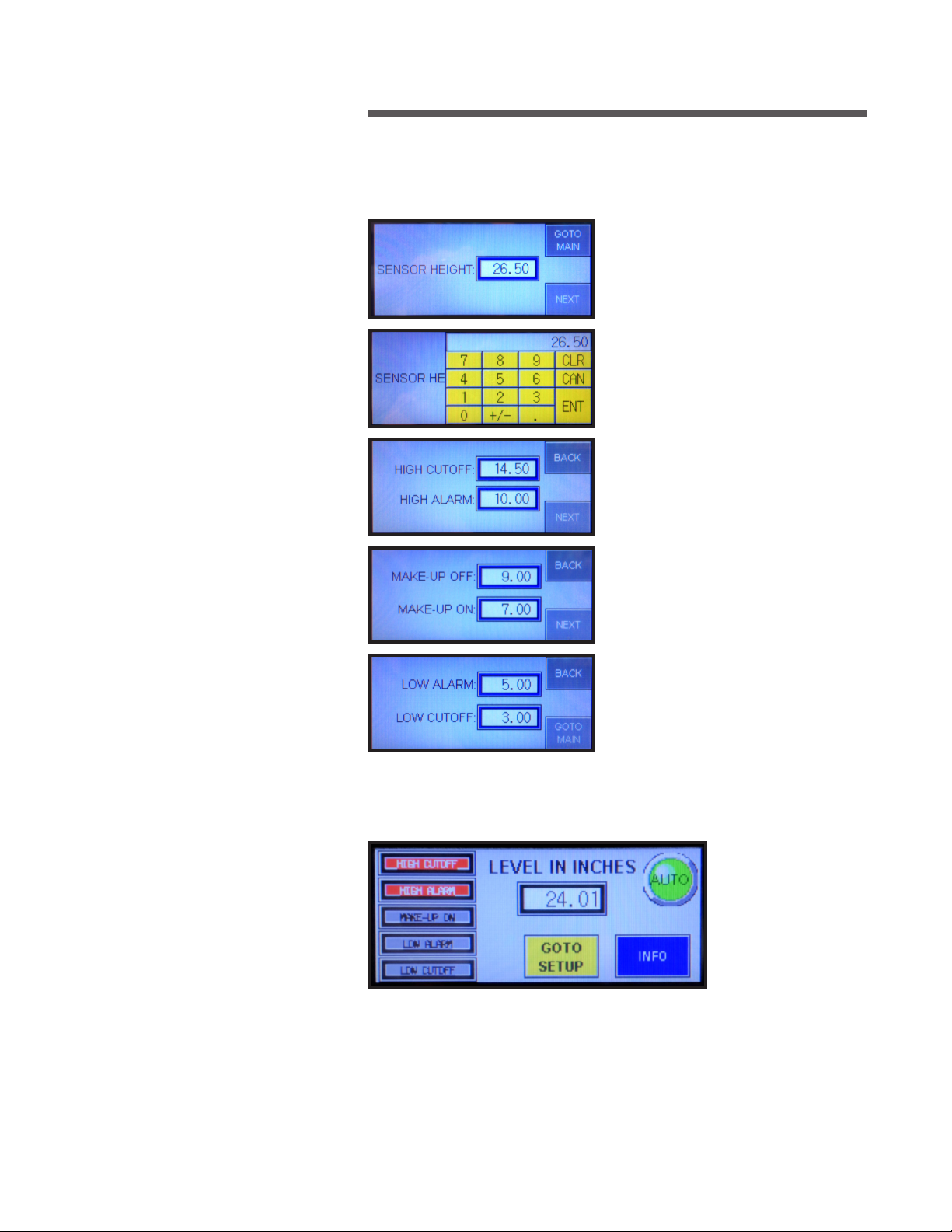
Programming is accomplished in the field based on recommended cooling
tower water level heights. Contact your Marley sales representative for recom-
mended setpoint levels. The sensor is programmed with a height from sensor
to bottom of the basin floor. Individual setpoint levels are programmed for high
cutoff, high alarm, makeup, low alarm and low cut off.
Alarm set point may be used to complete a remote BMS alarm circuit. Cut off
set point may be used to shut of a circulating pump.
A 4-20mA output is provided for BMS remote monitoring of water level
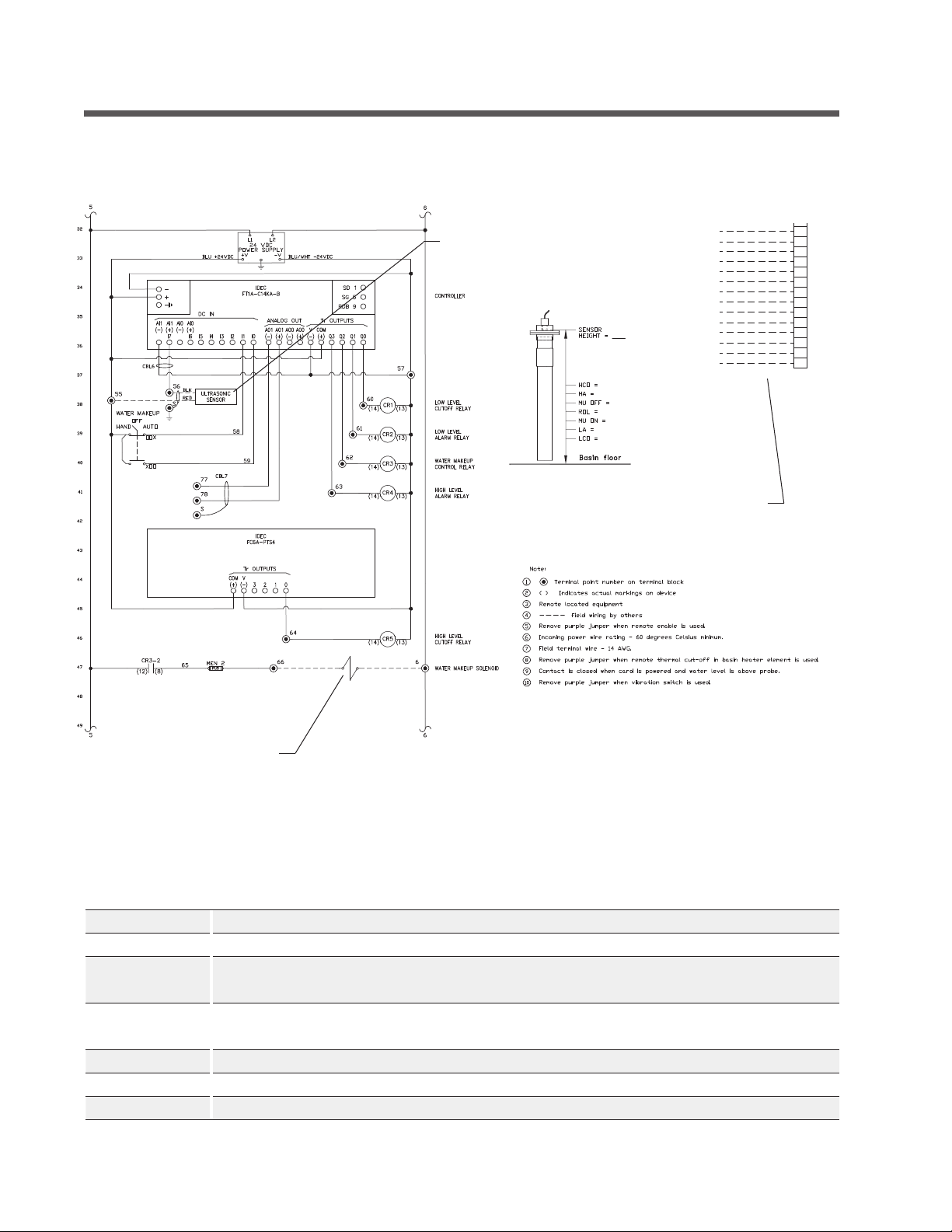
Water Makeup Function
The circuitry for water makeup in the LLC+ui control panel provides an inde-
pendent circuit breaker for direct connection to a 110-120VAC water solenoid
valve. This added feature allows customer installation without having to provide
an additional power circuit to energize the solenoid. The solenoid is connected
to terminals 2A and 4A as represented on the control’s specific wiring diagram.
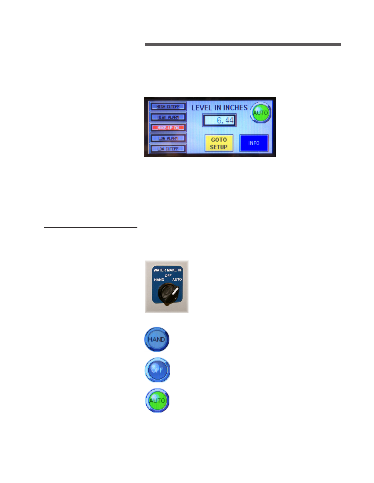
Purpose and Function of the HAND-OFF-AUTO Switch
Located on the right side of the control’s enclosure is a HAND-
OFF-AUTO switch. This switch is used primarily at cooling
tower startup and in maintenance procedures where the tower
basin is empty or has been drained. When the tower’s basin
needs to be manually filled, the switch is placed in the HAND
position. This selection bypasses the probe assembly’s feed-
back and directly energizes the solenoid valve connected to
the water supply. Once the cooling tower basin is filled, the switch is placed
in the AUTO position to allow the ultrasonic sensor to monitor and sustain
the proper operating level. Placing the switch in the OFF position completely
interrupts any monitoring or fill action normally provided by the LLC+ui control
panel. Normal tower operation depends upon the HAND-OFF-AUTO switch
being positioned in the AUTO mode at all times.