SPX POWER TEAM 6-HCR Use and care manual

Form No. 1000030A
6-HCR-C
Operating Instructions and
Parts List for:
Sheet No. 1 of 4
Rev Date: 11 Feb 2004
Tech. Services: (800) 477-8326
Fax: (800) 765-8326
Order Entry: (800) 541-1418
Fax: (800) 288-7031
SPX Corporation
5885 11th Street
Rockford, IL 61109-3699 USA
Internet Address:
http://www.powerteam.com
®
INTRODUCTION
The 6-HCR Hydraulic Cutter Remote is a lightweight,
compact and extremely durable tool that has been designed
for cutting a wide variety of materials.
The Cutter features insert type blades that can be easily
replaced in the field with the use of only a screwdriver. Other
features include a hinged “ Flip Top” Head and a full 360
Degrees of head rotation.
The Cutter can be operated with any suitable hand or power
pump capable of pressure output of 10,000 PSI. No special
control valves are required since the cutter piston is spring
returned.
The 6-HCR is not to be used for hot line work.
SPECIFICATIONS
Blade Opening: 7/8 Inch.
Head Rotation: 360 Degrees
Head Pivot on Hinge: 90 Degrees (Retracted)
Cutting Force: 12,265 lbs. at 10,000 PSI.
Oil required for full stroke: 1-1/2 Cu. In.
To t a l We i g h t : 4 . 6 l b s . ( 2 . 1 k g . )
Mating quick coupler: Power Team Part No 25599
CUTTING CAPACITIES (MAXIMUM
(See Notes)
Wire Rope: 3/4 inch Diameter
Soft Copper Bar: 5/8 inch Diameter
Soft Aluminum Bar: 1/2 inch Diameter
Soft Steel Bolts: 5/8 inch Diameter
Reinforcing Bar: 1/2 inch Diameter
Bare Stranded Copper Wire: 3/4 inch Diameter
Bare Stranded Aluminum Wire 3/4 inch Diameter
ACSR: 3/4 inch Diameter
Stranded Galvanized Steel Wire 5/8 inch Diameter
Underground Power Cable: 3/4 inch Diameter
WARNING
Notes:
Size shown are for stranded bare wires. When
cutting insulated wire, size is over insulation.
Rating for soft steel should not exceed ASTM
1022. Rating for hard drawn steel wire should not
exceed ASTM 1042.
6-HCR
HYDRAULIC CUTTER TOOL
Litho in USA
Operating Instructions and Parts List, Form No. 1000030A, Back sheet 1 of 4
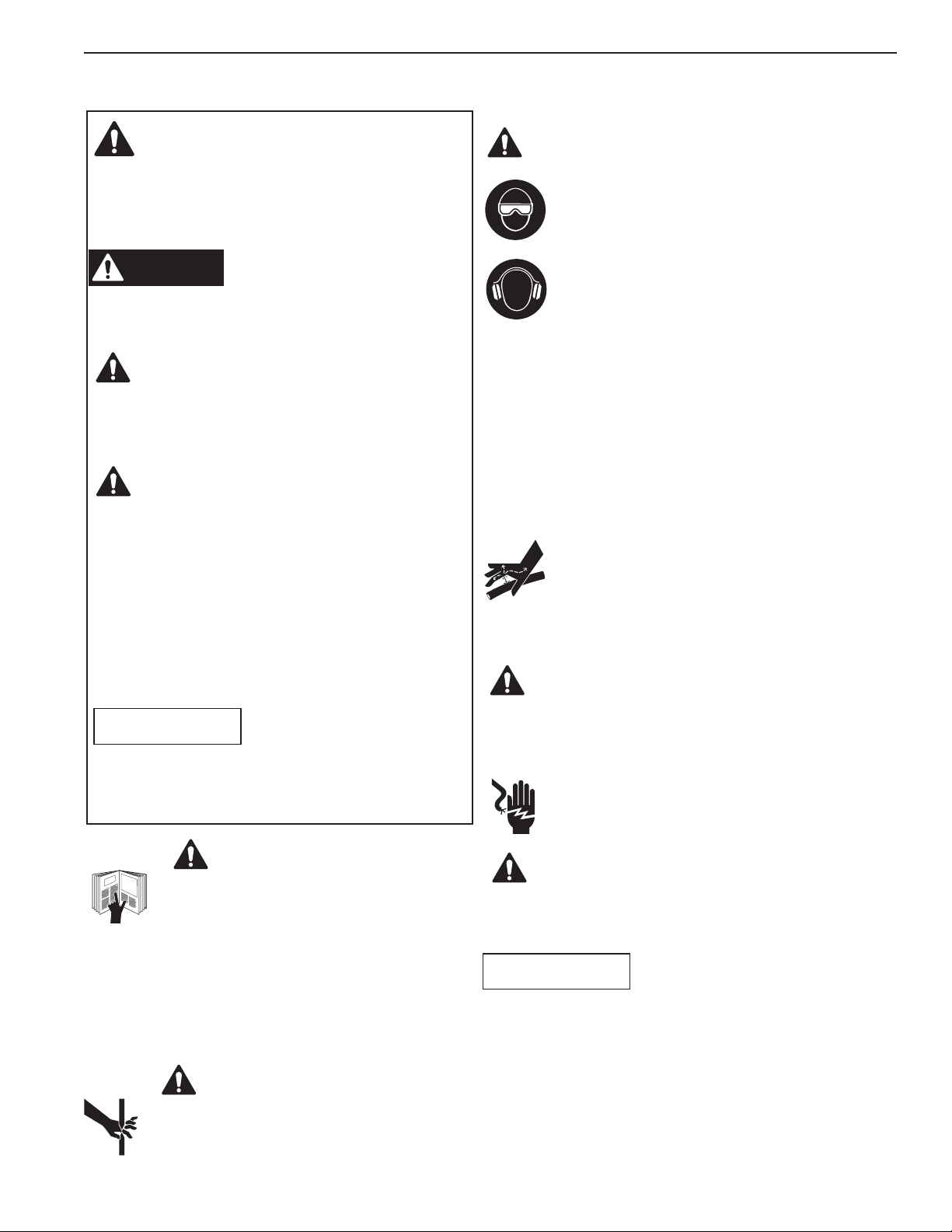
IMPORTANT SAFETY INFORMATION
It is the operators responsibility to read and
understand the following safety statements,
•Onlyqualifiedoperatorsshouldinstall,operate,
adjust, maintain, clean, repair, or transport this
machinery.
•Inspecttoolbeforeuse.Replaceanywornor
damaged parts. Failure to observe these warning
can result in severe injury or death.
Keep hands away from the cutter head
assembly head when cutting.
To help prevent personal injury,
•Alwaysweareyeprotectionwhenever
operating hydraulic equipment.
•Alwayswearhearingprotectionas
required.
•Operation,repair,ormaintenanceofhydraulic
equipment should be performed by a qualified
person who understands the proper function of
hydraulic equipment per local directives and
standards.
•Hydraulicequipmentmustbeassembledcorrectly
and then checked for proper function before use. Use
hydraulic components of the same hydraulic
pressure ratings. An appropriate hydraulic pressure
gauge is recommended to monitor pressure.
• Never place your hands or other body
parts near a hydraulic fluid leak.
Never use your hands or other body parts
to check for a possible leak.
High pressure fluid can be injected under your skin
causing serious injury and/or infection.
•Donotexceedcuttingcapacityofmaterialslistedon
sheet one. Cutting of too large or too hard materials
could cause blades to shatter and cause injury.
• This tool is not insulated. When using this
unit near energized electrical lines, use
proper personal protective equipment.
•Donotcutpianoormusicwire.
•Donotoperatecutterwithtopsupportopen.
•Properlydisposeofallfluids,components,and
assemblies at the end of their useful life.
•Hydraulicfluidshouldbecompatiblewithall
hydraulic components.
IMPORTANT
WARNING
CAUTION
This is the safety alert symbol.
It is used to alert you to potential personal injury
hazards. Obey all safety messages that follow this
symbol to avoid possible injury or death
Denotes an imminently hazardous situation which, if
not avoided, will result in death or serious injury.
Denotes a potentially hazardous situation which, if not
avoided, could result in death or serious injury.
Denotes a potentially hazardous situation which, if not
avoided, may result in minor or moderate injury.
Caution used without the safety alert symbol indicates
a potentially hazardous situation which, if not avoided,
may result in property damage.
Denotes an operating or service procedure or condition
considered essential for expedient and efficient
operation and service.
IMPORTANT
CAUTION
CAUTION
WARNING
DANGER
WARNING
WARNING
Sheet No. 2 of 4
Rev Date: 11 Feb 2004
Operating Instructions and Parts List, Form No. 1000030A
OPERATING INSTRUCTIONS
Connect cutter and hose to any suitable hydraulic pump that has pressure
output of 10,000 PSI. The mating half of quick-coupler supplied with cutter is
Power Team Part No. 25599.
Pump should be equipped with 2 or 3-way valve. Put the valve in the retract
position and retract cutter piston fully.
If part to be cut is very long, open cutter head by pulling out pull pin assembly,
slide cutter over part and close head, locking in place with pull pin assembly
fully engaged.
Place valve in advance position and advance piston with pump until lower
blade closes on material. Continue pumping until material is cut and stop
pump when cut is complete to avoid bottoming out piston in cutter and
pumping over relief valve. Although cutter has been designed to overcome
this, repeated bottoming of piston in tool puts unnecessary load on tool and
shortens the life of relief valve.
Retract piston and remove material from cutter.
Note:
After extended use or cutting hard materials, blades will become worn and
pitted. Kit No. 4-1238 is available from the factory for blade replacement.
Replace worn or damaged blades to maintain safe, efficient cutting operations.
Blade Replacement (Kit No. 4-1238)
To r e p l a c e t o p b l a d e, w i t h d r a w p u l l p i n a s s e m bl y a n d o p e n t o p s u p p o r t . R e m o ve s l o t t e d s c r e w a n d t o p bl a d e . I n s e r t
new top blade with flat side facing bottom blade and secure with new slotted screw and lockwasher.
To r e p l a c e b o t t o m b l a d e, a d v a n c e p i s t o n u n t i l b o t t o m bl a d e s c r e w i s ex p o s e d . R e m o v e h ex s o c ke t s c r e w a n d b o t t o m
blade. Insert new bottom blade with flat side facing top blade and secure with new screw.
Close top support and replace pull pin assembly. Cutter is now ready for use.
PERIODIC MAINTENANCE:
Occasionally lubricate pull pins and pivot pins with a molybdenum disulfide grease. The greatest single cause of
failure for hydraulic tools is dirt. Extreme caution should be used to prevent the entry of contaminant's into the unit.
Oil Leaks
A slight weeping of oil from the ram and pump seals is normal and required to keep moving parts lubricated.
Excessive leakage indicates a need for seal replacement.
Seal Replacement
Maintenance and repairs of this type should only be preformed by properly trained personnel in repair shops under
clean conditions. In addition to all parts shown on keyed parts list, 4-1162 Seal Kit is available for this purpose.
6-HCR (Open Position)

Operating Instructions and Parts List, Form No. 1000030A, Back sheet 2 of 4
TROUBLE SHOOTING
If the blade will not extend completely, it will generally be found that there is an insufficient amount of oil in the cutter's
hydraulic system.
If the blade will not retract completely, it will generally be found that there is too much oil in the cutter’s hydraulic
system. Drain enough to permit complete retraction. If the blade will not retract and the oil reservoir is not full, the ram
is likely being held by a deformed washer.
A small amount of leakage is desirable around the ram; to lubricate this part. If enough leakage occurs to cause the
oil to run, the packing should be replaced.
Compatible Hydraulic Fluids:
The use of Amoco Rykon MV oil is recommended. Compatible fluids include:
Mobil DTE 13
Mobil ATF 220
Shell Tellus 32
Arco Dexron III
Citgo AW32
Citgo Dexron III
Other fluids also may be used if they meet or exceed the following specifications:
Viscosity: 180 SSU at 100 degree F.
Flash Point: 350 degree F
Pour Point: -50 degree F
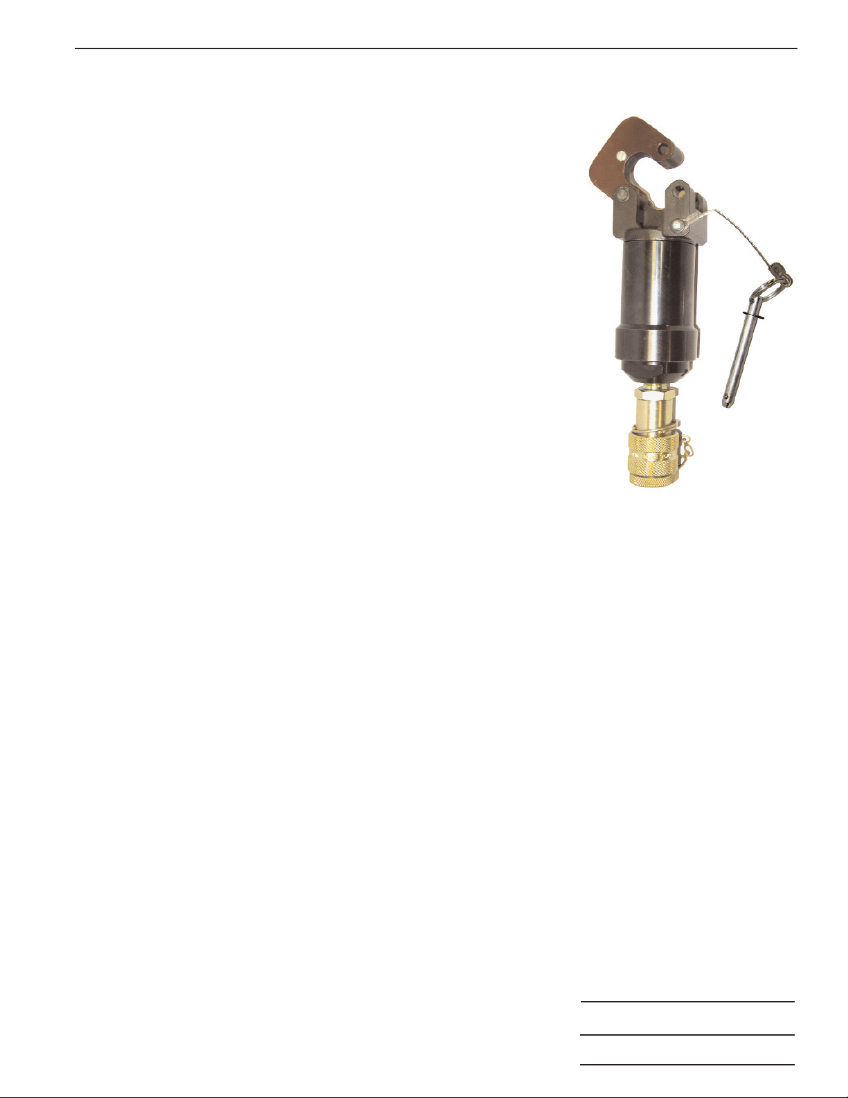
1. Pull Pin Assembly
2. Cutter Head Assembly
3. Adapter
4. Connector
5. Female-coupler
6. Dust-Cap
Illustration
6
5
234
1

Sheet No. 3 of 4
Rev Date: 11 Feb 2004
Operating Instructions and Parts List, Form No. 1000030A
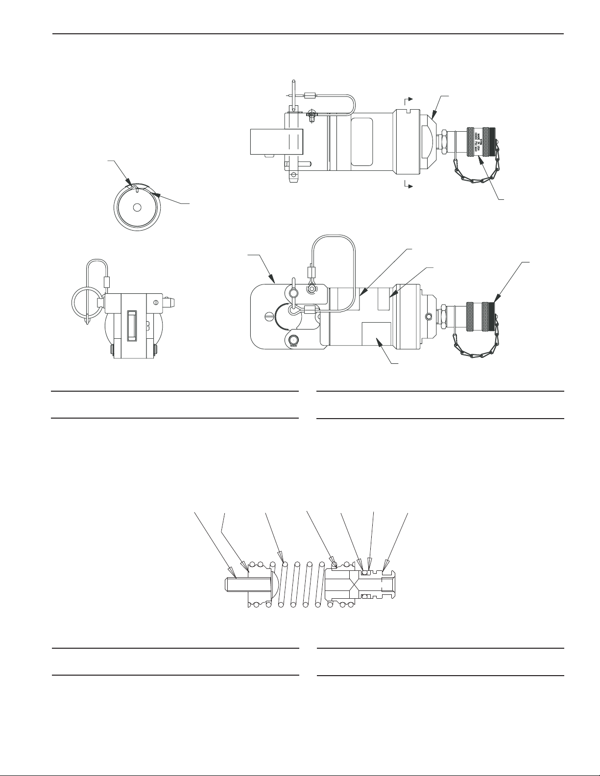
INSTRUCTIONS FOR CONVERSION TO 6-HHC TOOL
1. Fully retract tool ram and make sure all pressure has dissipated. Disconnect tool from hose to pump.
2. Remove adhesive label covering slot in cylinder.
3. Using a thin-bladed screwdriver or punch, pry hooked end of retaining wire out of slot in cylinder.
4. Holding hooked end of wire with pliers, rotate cylinder to force retaining wire out of groove and through slot.
Discard wire.
5. Carefully separate end cap assembly from cylinder assembly.
6. Apply lubricant to groove in pump block and to retaining wire.
7. Insert pump block assembly into back end of cylinder assembly, holding discharge spring in place. Rotate
cylinder assembly until hole in pump block appears in slot in cylinder.
8. Place hooked end of new wire from conversion kit into hole in pump block. Align free length of wire along slot
in cylinder. Rotate cylinder assembly in opposite direction to feed wire through slot and into groove.
9. When wire is fully engaged, hooked end will snap out of hole in end cap to permit full head rotation.
Wedge spring pin in slot in cylinder, allowing wire to move freely beneath. Seal slot with new adhesive label.
10. Purge air from remote tool and pump system using normal fill and bleed procedures.
WIRE SLOT IN CYLINDER
6-HHC TOOL
CUTTER HEAD SUB-ASSEMBLY
(PART NUMBER 4-0866)
PUMP ASSEMBLY
(PART NUMBER 3000089)
CONVERSION ASSEMBLY
(PART NUMBER 4-0766)
1-RETAINING WIRE
1-WRAP AROUND DECAL
®
SPX Corporation, Rockford, IL 61109 USA
http://www.powerteam.com Made in USA
®
SPX Corporation, Rockford, IL 61109 USA
http://www.powerteam.com Made in USA
®
SPX Corporation, Rockford, IL 61109 USA
http://www.powerteam.com Made in USA
Operating Instructions and Parts List, Form No. 1000030A, Back sheet 3 of 4
PARTS LIST
13-9990 1Cap,End
29796 1Coupler,Female(3/8”NPTF)
33-9678 1Wire,Retaining
44-0866 1HeadAssembly,6-TonCutter
51000054 1Decal,Warning
61000056 1Decal,
(Tradename Power Team)
79797 1Plug,Dust
8420691 1Decal,ProductBlank
Item Part No. Item Part No.
No. No. Req’d Description No. No. Req’d Description
A
A
Apply "White Lube" Lithium Grease (213083)
to groove and wire before assembling.
SECTION A-A
3
1
2
45
67
8
6-HCR
14-1263 1Spring,Tension
24-0697 1Retainer,Fixed
34-0698 1Retainer,Swivel
44-0699 1Tube,Transfer
510266 1O-Ring
65-3880 1Screw,BHSC
75-3245 1Ring,Back-up
Item Part No. Item Part No.
No. No. Req’d Description No. No. Req’d Description
6213574
SPRING ASSEMBLY 4-0695

Operating Instructions and Parts List, Form No. 1000030A
PARTS LIST
Sheet No. 4 of 4
Rev Date: 11 Feb 2004
13-8682 1Pin,Pivot
23-9008 1CableAssembly
33-9166 1Washer
44-0981 1Wire,Retaining
53-9694 1Blade,Top
63-9695 1Blade,Bottom
73-8672 1Support,Top
84-0691 1Piston
94-0692 1Cylinder
10 4-0694 1Yoke
11 4-0695 1Spring,Assembly,Return
12 10266 1O-Ring
13 10279 1O-Ring
14 251925 2Ring,Retaining
15 19140 1Ring,Back-up
16 5-3245 1Ring,Back-up
17 5-3627 1Screw,Drive
18 5-3678 1Screw,BottomBlade
19 11032 1Ring,Retaining
20 5-3624 1Screw,TopBlade
21 5-3867 1PinAssembly,Pull
22 4-0985 1Bushing
23 5-3868 1Ring,Grip
Item Part No. Item Part No.
No. No. Req’d Description No. No. Req’d Description
AA
21
2
17 3
1
14
20
5
611
18 15
13 19
16 12
SECTION B-B
SECTION A-A
SECTION D-D
B
B
C
C
D
D
SECTION C-C
4
710
22 89
23
Apply "White Lube"
Lithium grease (213083)
to wire and groove
before assembling
HEAD ASSEMBLY 4-0866
This manual suits for next models
1
Table of contents
Other SPX Cutter manuals


