SPX Pearlpoint P374 User manual

Ðíéì
× Ò Ì Î × Ò Í × Ý ß Ô ÔÇ Í ß Ú Û Ý Ñ ÔÑ Ë Î Ýß Ó Û Î ß
Ø Ý í é ì Óß Ò ó ê × Í Í Ë Û ê ð ì ñ î ð ïí Î Û ß Ü ß Ò Ü Ë Ò Ü Û Î Í Ìß Ò Ü Ì Ø × Í Ó ß Ò Ëß Ô Ð Î × Ñ Î Ì Ñ Ñ Ð Û Î ßÌ × Ò Ù Ì Ø Û Í ÇÍ Ì Û Ó
Ë Í Û Î Ó ß Ò Ë ß Ô


P374 System User Manual Section 1
© Pearpoint Ltd 2-1
COPYRIGHT NOTICE
The information within this publication is authorised for distribution to
customers, authorised service centre personnel, and distributors of Pearpoint.
Every effort has been made to supply information within this publication which
is correct. However, Pearpoint assumes no responsibility for its use nor any
infringements of patents or other rights of third parties which would result. No
licence is granted by the manufacturer under any patent or patent rights. The
manufacturer reserves the right to modify and update the equipment at any time
without prior notice.
No part of this publication may be reproduced, stored in a retrieval system, or
transmitted in any form or by any means to a third party without the prior
consent of the copyright holder.
The manufacturer's warranty will be invalidated if the equipment is operated by
untrained personnel or if any attempt is made to service the equipment by
untrained personnel.
REVISION HISTORY
Revision Date Comments
1.0 November 2001 First Issue
2.0 July 2002 FM Approval
3.0 Nov 2003 New ATEX Information Added
4.0 Nov 2006 Minor corrections and additions
Radiodetection Ltd
Western Drive
Bristol
Telephone: +44(0)117 976 7776
Facsimile: +44(0) 0117 976 7775
http://www.radiodetection.com
Manual part number: HC374MAN-1
i

Section 1 P374 System User Manual
© Pearpoint Ltd
2-2
CONTENTS
Page
1. GENERAL INFORMATION 1-1
1.1 WARNINGS, CAUTIONS AND NOTES 1-1
1.2 SAFETY PRECAUTIONS 1-1
1.3 SIRA CERTIFICATION 1-2
1.4 FM CERTIFICATION 1-5
1.5 EMC COMPLIANCE STATEMENT 1-7
1.6 INTRINSICALLY SAFE CONSIDERATIONS 1-9
1.7 RETURNS PROCEDURE 1-11
2. SYSTEM PREPARATION AND CONNECTION 2-1
2.1 INTRODUCTION 2-1
2.2 OVERVIEW 2-1
2.3 CONNECTIONS 2-1
2.4 SET MONITOR DISPLAY 2-2
2.5 ROD COUNTER SYSTEM 2-2
2.6 ROD CALIBRATION 2-3
2.7 ZERO THE ROD COUNTER 2-3
3. P374 INTRINSICALLY SAFE FLEXIPROBE 3-1
3.1 SETTING MANUAL FOCUS 3-1
3.2 SKID SETS 3-3
3.3 FITTING 100MM (4”) BRUSH SKIDS 3-4
3.4 FITTING 100MM (4”) AXIS SKIDS 3-5
3.5 FITTING 100MM (4”) AXIS SKIDS LIVE GAS MAIN INSERTION 3-6
3.6 USER MAINTENANCE 3-7
3.7 USER REPAIRS 3-8
3.8 OPTIONS 3-10
4. TEXT EDITOR 4-1
4.1 KEYBOARD FUNCTIONS 4-1
4.2 SET CURRENT DATE - [SET] [DATE] 4-1
4.3 SET CURRENT TIME - [SET] [TIME] 4-2
4.4 SET ROD COUNTER - [SET] [COUNT] [SET] 4-2
4.5 SET LANGUAGE - [CONF] [LANG] 4-2
4.6 SET MEASUREMENT UNITS - [CONF] [UNITS] 4-2
4.7 SET DISPLAY COLOUR - [CONF] [DISP] 4-2
4.8 SYSTEM RESET [CONF] [FCLR] 4-2
4.9 USER TEXT PAGES - [SET] [USR] 4-2
4.10 CREATING TEXT ON A PAGE. 4-3
4.11 ENTERING FIELDS ONTO A PAGE 4-4
4.12 DELETING FIELDS FROM TEXT 4-4
ii

P374 System User Manual Section 1
© Pearpoint Ltd 2-3
4.13 DELETING A CHARACTER 4-4
4.14 DELETING A LINE 4-4
4.15 DELETING EVERYTHING ON A PAGE 4-4
4.16 DELETING EVERY PAGE 4-5
4.17 CORRECTING A CHARACTER 4-5
4.18 INSERTING A CHARACTER 4-5
4.19 INSERTING A LINE 4-5
5. SPECIFICATIONS AND TROUBLESHOOTING 5-1
5.1 GENERAL EQUIPMENT SPECIFICATION 5-1
5.2 TROUBLESHOOTING 5-1
iii
Section 1 P374 System User Manual
© Pearpoint Ltd
2-4
GENERAL INFORMATION
1.1 WARNINGS, CAUTIONS AND NOTES
Within this handbook, pay particular attention to Warnings, Cautions, and
Notes, examples of which are shown below.
INDICATES THE POSSIBILITY OF PERSONAL INJURY IF INSTRUCTIONS ARE
NOT FOLLOWED CAREFULLY.
C
Indicates a possibility of equipment damage if the instructions are not
followed carefully.
S
INDICATES SERVICEABLE PARTS
NNOTE. Gives added information that will make operation of the equipment
easier.
1.2 SAFETY PRECAUTIONS
C
The P374 Inspection System is designed to reduce hazards from electric
shock provided that proper operating procedures are followed. If it is
operated in an outdoor environment it is imperative that proper earthing
procedures are followed. Use of a Residual Current Detector (RCD) is
strongly recommended [USA - Ground Fault Interrupter (GFI)]
Ensure the system is not placed in or near surface water.
Always ensure that cabling is properly connected.
Always transport a generator with the minimum amount of fuel in the
tank.
Never connect or disconnect any part of the equipment when it is switched
on.
Always switch the system on and off using the mains supply switch.
Clean and sterilise equipment at regular intervals.
ALWAYS USE HEAVY DUTY INDUSTRIAL GLOVES WHEN HANDLING ROD OR
CABLE WHICH IS BEING WITHDRAWN FROM A SEWER.
TO AVOID RISK OF BURNS,DO NOT TOUCH THE CAMERA HEAD WHEN IT IS
SWITCHED ON OR IMMEDIATELY AFTER SWITCH OFF. LEAVE AMPLE TIME
FOR IT TO COOL BEFORE HANDLING.
ARISK ASSESSMENT SHOULD BE PERFORMED PRIOR TO COMMENCING
WORK AS IT MAY HIGHLIGHT ADDITIONAL SAFETY ISSUES SPECIFIC TO THE
APPLICATION
1-1

P374 System User Manual Section 1
© Pearpoint Ltd 2-5
1.3 SIRA CERTIFICATION
1-2

Section 1 P374 System User Manual
© Pearpoint Ltd
2-6
1-3

P374 System User Manual Section 1
© Pearpoint Ltd 2-7
1-4

Section 1 P374 System User Manual
© Pearpoint Ltd
2-8
1.4 FM CERTIFICATION
1-5

P374 System User Manual Section 1
© Pearpoint Ltd 2-9
1-6

Section 1 P374 System User Manual
© Pearpoint Ltd
2-10
1.5 EMC COMPLIANCE STATEMENT
FCC CLASS B RADIO FREQUENCY INTERFERENCE STATEMENT
This equipment has been tested and found to comply with the limits for a Class
B digital device, pursuant to Part 15 of the FCC Rules. These limits are designed
to provide reasonable protection against harmful interference in a residential
installation. This equipment generates, uses, and can radiate radio frequency
energy and, if not installed and used in accordance with the instructions, may
cause harmful interference to radio communications. However, there is no
guarantee that interference will not occur in a particular installation. If this
equipment does cause harmful interference to radio or television reception,
which can be determined by turning the equipment off and on, the user is
encouraged to try to correct the interference by one or more of the following
measures:
Reorient or relocate the receiving antenna.
Increase the separation between the equipment and the receiver.
Connect the equipment to an outlet on a circuit different from that to
which the receiver is connected.
Consult the dealer or an experienced radio/TV technician for help.
DOC Notice (Canada Only)
This digital apparatus does not exceed the Class B limits for radio noise
emissions from digital apparatus as set out in the Radio Interference Regulations
of the Canadian Department of Communications.
Le present appareil numerique n'emet pas de bruits radioelectriques depassant
les limites applicable aux areils numeriques de Classe B prescrites dans le
Reglement sur le Brouillage Radioelectrique edicte par le Ministere des
Communications du Canada.
EUROPEAN COMMUNITY RADIO FREQUENCY INTERFERENCE
STATEMENT
This equipment has been tested and complies with the following harmonised
standards:
EN 50082-2 Provisional Immunity Standard encompassing static,
RF, and line borne transient immunity.
EN 50081-1 EMC emission standard.
EN 61000-3-2 Line Borne Harmonic Distortion
1-7

P374 System User Manual Section 1
© Pearpoint Ltd 2-11
1-8

Section 1 P374 System User Manual
© Pearpoint Ltd
2-12
1.6 INTRINSICALLY SAFE CONSIDERATIONS
The Pearpoint P374 system has been designed to be Intrinsically Safe even when
faults occur or when the equipment has been damaged due to misuse. However,
there are situations where the operator can cause a fire hazard if the following
guidelines are not adhered to:
Equipment earthing
The equipment must be operated at the same electrical potential as the subject
being inspected. This means that the P374 system and the subject being
inspected must be joined together electrically otherwise it is possible that a high
potential might exist between the equipment and the subject. Here are a few
examples:
Underground pipework. If the P374 is operated from a mains supply rather than
a generator there is usually no problem as any buried pipework will be at mains
earth potential ensuring that there is no potential difference between the camera
and subject. However, if the equipment is operated using a generator rather than
a mains supply then there is a possibility that a potential difference exists
between the P374 system and the pipework. As a general rule the potential
difference will not be sufficient to cause a problem as the P374 camera is
insulated to a voltage of greater than 500V. However, it is good practice to
ensure that the P374 system is bound to the same potential as the subject, this is
because an operator may build up a certain amount of static electricity and this
may be discharged through the P374 system.
When working with a generator it is imperative that the generator is earthed, this
can be done via the generator earthing point (see the generator manual for this
information). An earth wire must run from the generator to the subject, in the
case of underground pipes this can be an earthing stake. Where working on oil
platforms the metal structure of the platform can be used. If your generator does
not have an earthing point then an additional earth wire must be run from the
distribution connector (see your dealer for details).
When working with mains power ensure that the equipment is properly earthed,
be aware that some extension leads only carry 2 conductors for Live and Neutral
and miss out the earth conductor altogether. Also be aware that some isolating
transformers do not continue the earth conductor through between input and
output (although this is rare); ensure that the transformer you are using has a
continuous earth.
When working with the 12V supply input it is imperative that the negative
conductor is earthed. Quite often the 12V supply is derived from a motor
vehicle, this means that the P374 earthing system is connected to the chassis of
the vehicle and thus the P374 will assume the same potential as the vehicle. It is
well known that the chassis of vehicles can carry high voltages due to static
build-up and this voltage will be conducted to the P374 unit. For this reason the
chassis of the vehicle must be bonded to the subject being inspected, usually (in
the case of underground pipework) this means that the chassis of the vehicle is
connected to a ground-stake.
1-9

P374 System User Manual Section 1
© Pearpoint Ltd 2-13
1-10

Section 1 P374 System User Manual
© Pearpoint Ltd
2-14
1.7 RETURNS PROCEDURE
If any equipment has to be returned to Pearpoint for repair or servicing, please
note the following precautions to be taken to ensure safe passage:
Always contact your service agent in advance.
Retain the original packaging material and re-use wherever possible.
If the original packaging material is not available, select a heavy duty
cardboard box and make liberal use of bubble pack or polystyrene
material to cushion and prevent movement of the component.
Clearly identify all equipment with the customer's name and address.
Where relevant, attach "Fragile" and "This Way Up" labels to the
packaging.
To the outside of one box, attach a copy of your order or work
instructions.Enclose these in an envelope, including your name and
address.
Never transport generators with fuel on board.
Always clean all contamination from the equipment prior to sending it to
Pearpoint.
Flexirods must be securely retained within the coiler or transportation
cage.
Equipment should be insured for carriage damage or loss.
1-11
P374 System User Manual Section 2
© Pearpoint Ltd 2-1
2. SYSTEM PREPARATION AND CONNECTION
2.1 INTRODUCTION
The P374 is a colour inspection system specifically designed for intrinsically
safe inspection needs. The P374 is a solid state, high resolution colour camera
which is fully immersible and can travel down pipes up to 60 metres (200 feet)
in length. The P374 camera operates from a Intrinsically safe low current
supplied through the coiler.
A variety of skids allow inspection of pipes from 25mm (1") to 100mm (4").
2.2 OVERVIEW
The system provides a self-contained video inspection system including camera,
rod, power supply and video monitor. When connected to a mains power supply
or a 12V supply the unit will be fully operational with the simplest of
preparation. The system also provides the means to play-back recorded media on
the integral LCD monitor by connecting any composite video source (PAL or
NTSC) to the 'Video in' BNC connector on the underside of the electronics
enclosure, video from the unit may also be recorded from the 'Video out' BNC
connector. The unit is supplied with a video text-writer, this can display the
users' text messages on-screen along with the cameras' distance measurement
and the date and time (this is updated automatically). The system is fully water
resistant to IP55, allowing for total wash-down of all components for cleaning
C
Do not use a high pressure water jet on the camera and electrical housing,
as there is a possibility of equipment damage.
The coiler is constructed from durable, cast aluminium and all parts are designed
for low maintenance.
2.3 CONNECTIONS
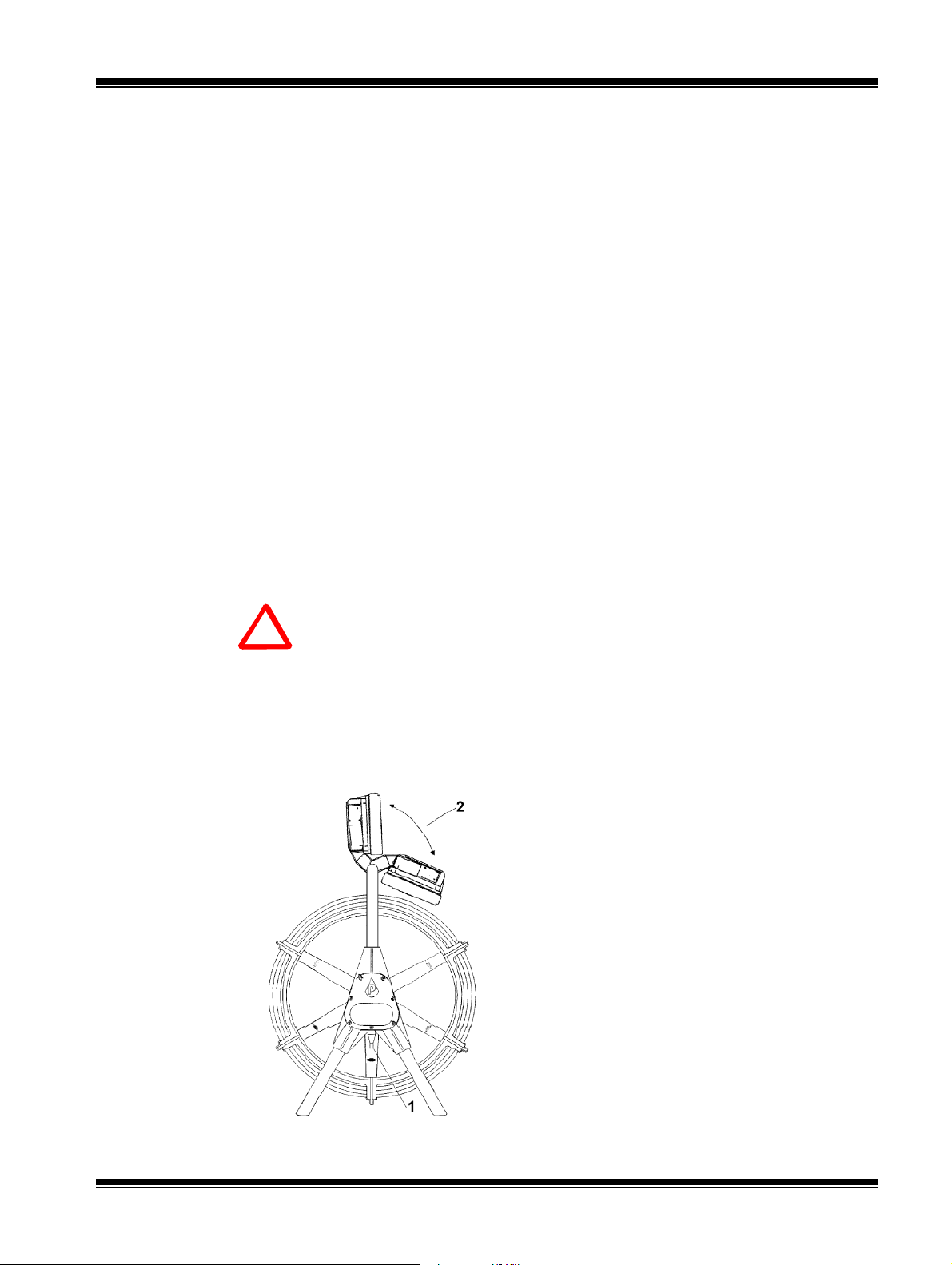
The system is very easy to prepare for use.
1. Ensure that the Power Lead is firmly plugged
into the socket (1) (see Connectors Diagram)
2. Push the monitor to the up-right position (2).
3. The P374 will power up as soon as it is
connected to an electrical supply.
4. If you wish to connect a VCR to your system, to
record or playback your survey the BNC
connectors are situated adjacent to the mains
cable (item 1) (see Connectors Diagram). You
will require a BNC cable which can be supplied
by Pearpoint as an option. When connected to
Video IN, the monitor will automatically display
your survey video.
5. If you wish to power your system from a 12V
DC supply, the socket is situated adjacent to the
mains connector (1). The cable will connect to a
Vehicle Cigarette/Cigar Lighter and is available
with the equipment as standard.

Section 3 P374 System User Manual
© Pearpoint Ltd
2-2
N
Connectors Diagram
FRONT
MAINS POWER INPUT
12VDC INPUT VIDEO INPUT (TO VIDEO RECO
VIDEO OU
T
(FROM VIDEO RECORDER)
On powering up, the Pearpoint message will be
displayed briefly and the camera and lights will
operate. The system is now ready to use.
A pull-out sun shade is available to reduce the effects
of bright sunlight on the monitor.
2.4 SET MONITOR DISPLAY
For the best quality monitor picture it is best to view the
monitor straight-on, the picture quality will degrade when
viewed from different angles.
You can adjust the quality of the displayed picture by using
the monitor set-up controls situated on the left hand side of
the monitor.
You can turn the knobs to adjust the brightness and colour
of the picture to suit your own requirements.
NOTE. The Hue control is for NTSC systems only.
2.5 ROD COUNTER SYSTEM
The rod counter display appears in the centre of the screen. The rod counter
requires calibrating on a regular basis to maintain accuracy.
NNOTE. Should the counter run outside calibration the message "counter
needs cal" will be displayed. You should carry out the procedure
detailed below.

P374 System User Manual Section 2
© Pearpoint Ltd 2-3
2.6 ROD CALIBRATION
1. Ensure all the rod is returned to the coiler.
2. Press the [ZERO] button and hold for five seconds. The message "press
again to cal" is displayed, release the [ZERO] button.
3. Press the [ZERO] button again. The message "cal complete" will be
displayed.
C
Pearpoint recommends the system is calibrated before use or on a daily
basis.
It is also advisable, on a regular basis, to confirm the absolute accuracy of
your counter by means of a physical check of rod length. This involves
calibrating the rod, setting the counter to zero, and pulling 20m (60 ft) of
rod from the coiler. You can compare the physical measurement with the
rod counter reading displayed on the screen. The displayed rod length
should be within ±60cm (2 ft) of the physical length.
2.7 ZERO THE ROD COUNTER
The rod counter can be set to zero at any time. This is useful if you wish to
restart your survey at a particular point. To zero the counter:
1. Press the [ZERO] button three times in quick succession. The counter will
read zero.

Table of contents
Other SPX Digital Camera manuals


