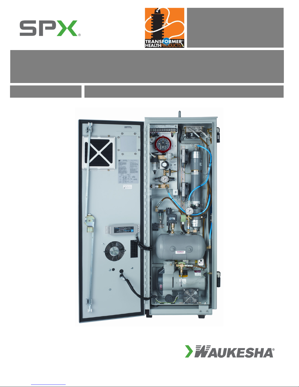
2nd GENERATION NITROGEN GENERATOR SYSTEM MANUAL
N2-Gen-Manual REV 3.8, 8/2014
Patented 2nd Generation Nitrogen Generator Systems are manufactured and distributed by Waukesha®Service & Components, a division of
SPX Transformer Solutions, Inc. U.S. Patent Nos. 6,581,694; 6,568,287; 6,062,821; 5,902,381 and 5,744,764.
4
SAFETY INFORMATION
Proper use of this equipment is important for your personal safety and for trouble-free functioning of the unit.
Incorrect control or attempts to perform adjustments could cause damage or lead to incorrect gas supply. Be
sure to read and understand all instructions before attempting to operate the unit. The unit is designed to
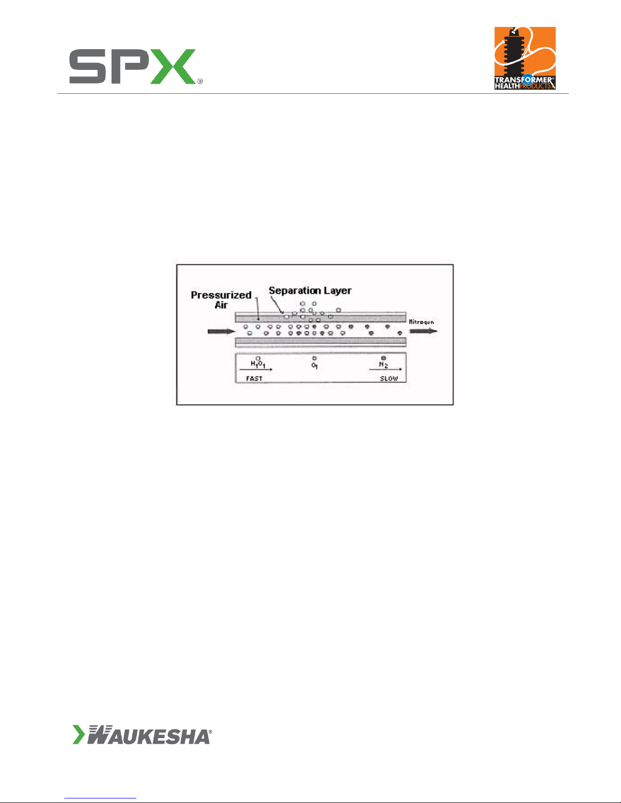
produce nitrogen. The nitrogen is supplied by an internal generator that produces nitrogen from ambient air
through a process of separating oxygen from normal air. You must not use the unit for any other purpose
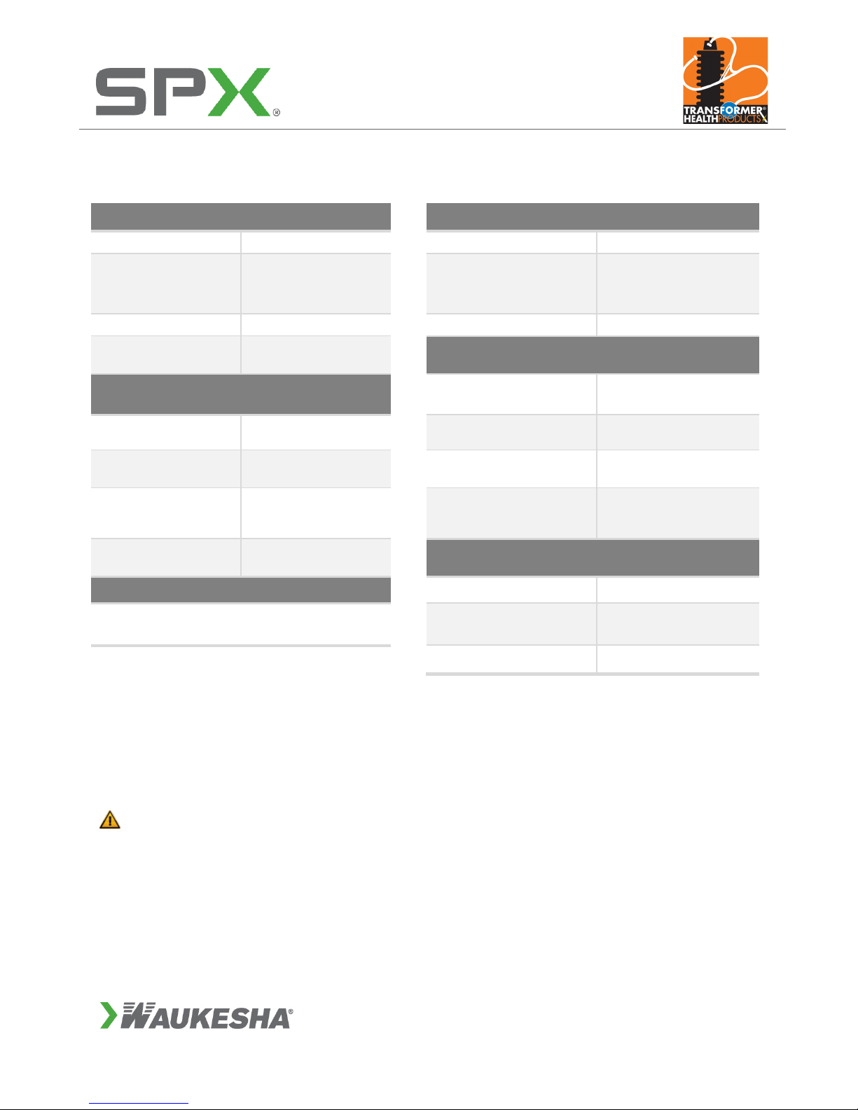
than what is specified. Do not operate the unit beyond its limits (see Specifications table on page 5). In
addition to the warnings and cautions in this manual, use the following safety guidelines for safe operation
of the unit:
WARNING: This unit is an electrical appliance. Make sure that the main power supply is
disconnected before you perform installation, maintenance or repair work.
WARNING:If you must work on the equipment with the main power supply on, be aware of
electrical hazards.
DANGER:When working on the equipment, do not wear loose clothes, jewelry or hair. They
could become entangled in the fan blades.
WARNING:The compressor becomes very hot when operating. Be careful when you open
the cabinet after the unit has been operating for any length of time. Do not touch the
compressor. Allow it to cool down before you start to perform any service on the unit. If you
must work on the unit while it is hot, be sure to wear protective gloves to protect yourself
from the heat.
CAUTION:Do not block the ventilation inlets and outlets as this could cause overheating
and damage to the unit.
CAUTION:Do not allow the AC unit to be positioned other than vertical. If the AC is
positioned horizontally, reposition to a vertical position for 12 hours before starting unit.
WARNING:In order to prevent injury or damage caused by the sudden release of
compressed air, make sure that the unit and connected systems are fully depressurized
before you start uncoupling parts of the system. Make sure no one tampers with the
pressure-relief valve.
DANGER:This unit produces nitrogen and oxygen-enriched air. Nitrogen can cause
suffocation. Oxygen-enriched air can lead to increased risk of fire in the event of contact
with flammable products. Ensure adequate ventilation at all times.
IMPORTANT The following words and symbols appear throughout this manual and designate important
safety instructions:
DANGER:Indicates information important to the proper operation of the equipment. Failure
to observe will result in damage to the equipment and/or severe bodily injury or death.
WARNING:Indicates information important to the proper operation of the equipment. Failure
to observe may result in damage to the equipment and/or severe bodily injury or death.
CAUTION:Indicates information important to the proper operation of the equipment. Failure
to observe may result in damage to the equipment.
Read all safety instructions to avoid personal injury or death and to avoid damage to the unit or property.