Veichi SI30 series User manual

NEW SI30 Solar Pump Inverter

SI30 Solar Pump Inverter Manual
1
Chapter 1 Safety Requirement and Cautions
To ensure safety of your health, equipment and property, please read this chapter carefully before
using the solar pump inverter and act in compliance with the instructions when installing, debugging,
running and overhauling the inverter.
1.1 Safety Definition
Danger: it will cause danger of serious injuries and even death while operating against the rules.
Caution: it will cause danger of light injuries or equipment destruction while operating against the
rules.
Note: some information is useful while operating and using solar pump inverter.
1.2 Safety Requirements and Cautions
● Before Installation
Danger
1. Only qualified personnel can operate the equipment. Before operating, be sure to carefully
read the manual. The safe operation depends on the proper processes of choosing models,
carrying, installation, operation and maintenance.
2. Don’t use the damaged or incomplete solar pump inverters; Otherwise, there is risk of injury.
● Installation
Danger
1. Please install the solar pump inverter on metal or other nonflammable material, and keep it
away from the combustible material. Otherwise there is danger of fire.
2. No unauthorized modification to the solar pump inverter; Otherwise there is danger of
damage.
3. Normal solar pump inverter without explosion-proof cannot be installed where with explosive
gas or dust; Otherwise there is danger of explosion.
● Wiring
Danger
1. Wire is connected only when the main circuit is cut off, otherwise there is a danger of shock.
2. Wire is connected by professional person only. Otherwise there is a danger of shock.
3. Earth must be reliable. Otherwise there is a danger of shock.
4. DC power supply should not be connected to output terminals U, V, W, otherwise there is a
danger of damage to solar pump inverter.
5. No drop of bolt, spacer, metal stick, conducting wire or other things into the inner of solar
pump inverter; Otherwise there is a danger of fire or damage to solar pump inverter.

SI30 Solar Pump Inverter Manual
2
Attention
1. If the damage to solar pump inverter or other equipment is caused by improper wiring and
utilization or unauthorized alteration, the user should shoulder all responsibilities.
2. Please make sure all wirings meet EMC requirements and satisfy safety standards in the
local area; Please refer to recommendations in this manual or national standards of wire
diameter to avoid accidents.
3. Static electricity on human body would seriously damage internal MOS transistor, etc. Don’t
touch the printed circuit boards, IGBT or other internal devices without anti-static
measurements;otherwise it will cause the malfunction to solar pump inverter.
4. Please don't connect phase shift capacitance or LC/RC noise filter to the output circuit of
solar pump inverter; Otherwise it will damage the inverter.
5. Please don't connect the magnetic switch or magnetic contactor to the output circuit of solar
pump inverter; When solar pump inverter is in the operation with load, magnetic switch or
magnetic contactor can make inverter over-current protection act. It will damage solar pump
inverter seriously.
6. Please don't dismantle the panel cover, and it only needs to dismantle the terminal cover
when wiring.
7. It is forbidden to do any pressure test on solar pump inverter, otherwise it will damage the
solar pump inverter.
● Before Electrification
Danger
1. Please make sure that voltage grade of power supply is consistent with solar pump inverter's
rated voltage and then check whether the wiring is correct, and whether there is short circuit
in peripheral equipment's circuit. Otherwise it will damage solar pump inverter and other
equipment.
2. Before the solar pump inverter is connected to the input power supply, make sure that the
cover has been well fixed. Otherwise it will cause electric shock.
3. For the solar pump inverters whose storage time is over 1 year, when electrification, the
voltage should be raised by booster from low to high. Otherwise it will damage the solar
pump inverter.
Attention
1. Check if all periphery fittings are wired properly according to the handbook; Otherwise it will
cause accidents.

SI30 Solar Pump Inverter Manual
3
● After Electrification
Danger
1. After electrified, it is forbidden to open the cover, make wiring, and check up; Otherwise, it will
cause the danger of electric shock.
2. After electrified, it is forbidden to contact internal wiring board and its parts. Otherwise it will
cause the danger of electric shock.
3. Do not operate or touch solar pump inverter with wet hand. Otherwise there is danger of
damage to solar pump inverter and electric shock.
Attention
1. Please set the parameter of solar pump inverter cautiously; Otherwise it will damage
equipment.
● Operation
Danger
1. Before running, please check and confirm the application range of the machine and
equipment once more; Otherwise it will cause accidents.
2. Please don't touch the cooling fan and braking resistance to check the temperature;
Otherwise there is a danger of getting burn.
3. Unprofessional workers are banned to check the signals in the running stage; Otherwise it
will cause injuries and damage the equipment.
Attention
1. Please don't turn off the equipment by switching off power; Please cut off the power supply
after the electric machine stops running; Otherwise it will damage the solar pump inverter.
2. Please avoid anything dropping into the equipment when the solar pump inverter is running;
Otherwise it will cause electric shock.
● Maintenance
Danger
1. Please don't maintain and repair the equipment with electric; Otherwise it will cause electric
shock.
2. Before maintaining and repairing the solar pump inverter, please make sure the indicator
lights of power supply have completely turned off; Otherwise it may cause electric shock and
damage the solar pump inverter.
3. Persons who have not passed specialized train are not allowed to conduct the solar pump
inverter maintenance; Otherwise it may cause electric shock and damage the solar pump
inverter.

SI30 Solar Pump Inverter Manual
4
1.3 Cautions in Using
1. In application of this series solar pump inverter, you have to confirm all machine insulation to
prevent damage to the equipment. Moreover, when the motor working in tough environment, please
periodic inspect the electrical insulation to ensure the safety of the system work.
2. If the motor adapter is not consistent with solar pump inverter's rating current (The rating current
of the motor is far smaller than that of solar pump inverter), please adjust the protective value to ensure
safe running.
3. In occasions such as load raises, usually there is negative torque and solar pump inverter breaks
off for over-current or over-voltage. In this case, you should consider choosing the matching brake unit.
4. Solar pump inverter, in a certain output frequency range, can meet the mechanical resonance of
the load equipment. To avoid it, you can set up jumping frequency.
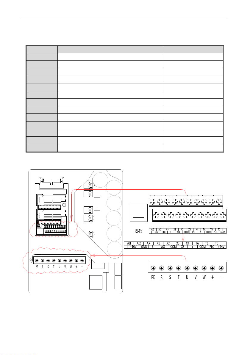
5. As output voltage of the inverter is pulse-wave type, if there is capacity which can improve power
factor or pressure-sensitive resistance which used for thunder-proof in the voltage output side, the solar
pump inverter will break off or its parts will be damaged, so it is necessary to dismantle them. Moreover, it
is proposed not install switch parts like air switch and contactor (if it is necessary to install switch on
output side, please make sure the output electricity of solar pump inverter is zero when the switch is
working).
6. At over 1,000 meters altitude, the inverter’s heat dissipation function worsened due to the thin air,
it is necessary to use less.
7. The inverter output voltage is pulse wave type. If using digital multi-meter measurement, deviation
of the reading will be great. And the deviation is different by using different type of digital multi-meter.
Under normal circumstances, while RMS 380V, digital multi-meter reading is around 450V.
8. Solar panel can be connected in series or parallel. For rated voltage 380V controller, we suggest
solar panel open circuit voltage should be between 620V~750V.
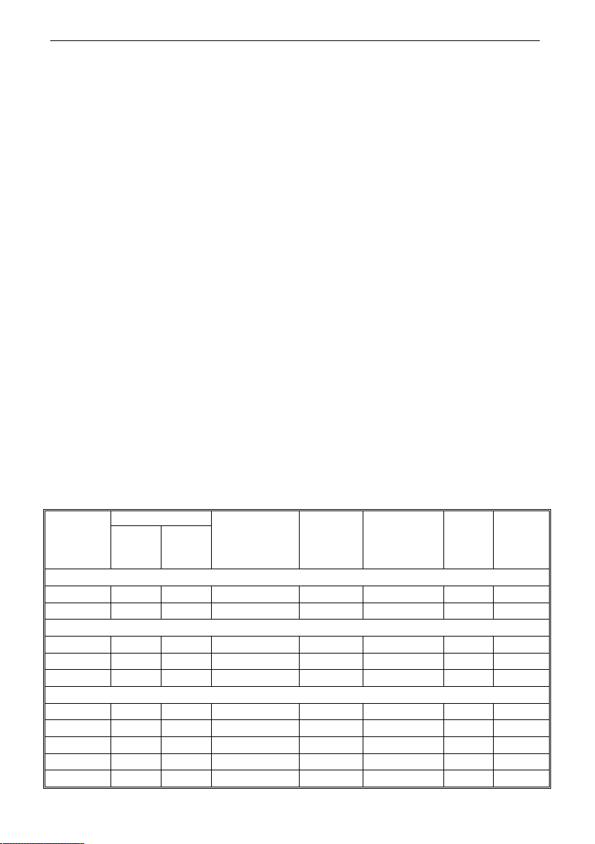
1.4 Technical Specification
Solar pump
inverter
power(kW)
Pump Max solar power
input
(kW)
Max DC
input
voltage (V)
Recommend
Voc voltage (V)
Rated
output
current
(A)
Output
frequency
(Hz)
Rated
power
(kW)
Rated
voltage
(V)
SI30-D1 series, DC90V-400V input,3 phase AC110V-230V output, MPPT voltage range DC90V-400V,for AC110V pumps
0.75 0.75 110 1.0 400 175~380 7A 0-320
1.5 1.5 110 1.95 400 175~380 10A 0-320
SI30-D3 series,DC150V-450V input,3 phase AC220V-240V output, MPPT voltage range DC150V-450V, for AC220V pumps
0.75 0.75 220 1.0 450 360~430 4A 0-320
1.5 1.5 220 1.95 450 360~430 7A 0-320
2.2 2.2 220 2.86 450 360~430 10A 0-320
SI30-D5 series,DC300V-850V input,3 phase AC230V-460V output, MPPT voltage range DC300V-800V,for AC380V pumps
0.75 0.75 380 1.0 850 620~750 2.5 0-320
1.5 1.5 380 2.2 850 620~750 3.7 0-320
2.2 2.2 380 3.3 850 620~750 5.0 0-320
4 3.7 380 5 850 620~750 10 0-320
5.5 5.5 380 8 850 620~750 13 0-320

SI30 Solar Pump Inverter Manual
5
7.5 7.5 380 10 850 620~750 17 0-320
11 11 380 14.3 850 620~750 25 0-320
1.5 Cautions in Disposal
When you dispose solar pump inverter, please pay attention to:
1. Electrolytic capacitor: the electrolytic capacitor of main circuit or the printing plate may explode when
they are burned.
2. Plastic: plastic incineration may generate toxic gases.
3. Dispose method: please dispose as industrial waste.

SI30 Solar Pump Inverter Manual
6
Chapter 2 Installation and Wiring
2.1 Products Appearance
2.2 Open Cover
Remove 4 fixed screws in the cover and turn from right to left to open the top cover, as shown below:

SI30 Solar Pump Inverter Manual
7
2.3 Wiring and grounded(The ground wire must be firmly connected)
2.4 Inverter Dimension
285
308
350
369
446.5
260
260
7.5(installation hole)
285
203

SI30 Solar Pump Inverter Manual
8
2.5
Terminal diagram
●
Control loop terminal instructions
Terminal
Function definition Description
+10V 10V auxiliary power supply output, constitutes loop with MAX output 50mA
+24V 24V auxiliary power supply output, constitutes loop with MAX output 100mA
COM 24V power reference ground MAX output 24VDC/100mA
A+ RS485 communications
+
B- RS485 communications
-
AI1 analog input 1 Voltage, current type optional
AI2 analog input 2 Voltage, current type optional
GND analog signal ground
X1 Forward running input, and constitutes loop with COM
X2 Reverse running input, and constitutes loop with COM
X3 Full water detection alarm, and constitutes loop with COM
X4 Full water detection reset, and constitutes loop with COM
RJ45 External keyboard connection terminal
2.6 Terminal diagram

SI30 Solar Pump Inverter Manual
9
Chapter 3 Basic Operation and Trial Run
3.1 Keyboard Layout and Function Specification (optional)
●
Keyboard Appearance
●
Key Function
Symbol
Double-line
keyboard Function
A Unit indicator Hz: Frequency A: Current V: Voltage V/A: Voltage or
current RPM: Speed %: Percentage
B Status Indicator On: Forward running status Blinking: Reverse running status
Off: Stop status
C
Menu Enter the function menu interface during standby or running;
press this button to exit the modification when the parameter is
modified; press the button (1 second) during standby or running
to enter the status interface directly.
F
Stop/Reset When the command given channel is keyboard control, press
this key to stop the inverter; the parameter [F04.08] can be used
to define whether other command channels are valid; the
inverter resets when pressing the key in fault status.
G
Digital potentiometer: clockwise to increase the operating value,
counterclockwise to decrease the operating value
Set key: After modifying the value, press this key to confirm the
modified value.
Left/Right Shift
Move left and right operation bits
H
Jog/Reverse Select the function of the key by parameter [F04.07], 0: reverse
1: jog

SI30 Solar Pump Inverter Manual
10
3.2 GPRS: IOT-GWS module and APP application (optional)
● IOT-GWS module appearance and wiring diagram
● APP main interface and function introduction

SI30 Solar Pump Inverter Manual
11
3.3 Panel button (standard configuration)
It is able to complete start /stop operation on inverter by pressing [Start/Stop] key in the cover panel
only when F0.02=0. Pressing the key to start it when it is in stop status. While it is in running status, press
the key to stop it. And user can also press the key to reset it when it is in fault status. The “Power”
indicator will be on once power on and “Run” indicator will be on when inverter is running. As fault comes,
“Fault” indicator will be always on. While “Fault” indicator is blinking, alarm comes.

SI30 Solar Pump Inverter Manual
12
Chapter 4 Fault Diagnosis and Solution
This chapter describes the inverter fault, alerts, and operation of the failure on the inverter, the
display information on inverter and countermeasures. In addition, the poor condition of the drive and
motor failures will be briefly described in this chapter. Tuning guide on commissioning of the drive please
refer this chapter.
Fault Information and Description in Detail
Keypad
display
Fault
code Fault type Possibility reason Troubleshooting
E.LU2
Under voltage
at runs
●Power voltage too low
●DC main contactor don’t
close
●Check input power to
solve
●Ask support
E.oU1
Over voltage
at
acceleration
●Power voltage fluctuation
over limit
●Too start rotating motor
●Check power grid
●Restart until motor is
stop completely, or
set[F1.00] set for 1 or 2
E.oU2
Over voltage
during
deceleration
●Deceleration time too small
●The driving load too heavy
●Power voltage
fluctuationover limit
●Prolong deceleration
time
●Reduce the load, or
select bigger capacitor
drive, or connect braking
unit
●Check input power
E.oU3
Overvoltage
at
constant
speed
●The input voltage is too
high
●An external force drives the
motor during deceleration
●Adjust the voltage to
normal range
●Cancel the external force
or install the braking
resistor
E.oU4
Over voltage
at stop
●Voltage fluctuate above
limit ●Check the input voltage
E.oC1
Over current
during
acceleration
●Acceleration time is too
short
●To start rotating motor
●V/F setting not correct or
torque boost setting too big
●Solar drive capacitor is too
small
●Prolong acceleration
time
●Restart motor when it on
still, or set F1.00 for 1 or 2
●Reset V/F curve or
torque boost setting
E.oC2
Over current
during
deceleration
●The output circuit is
grounded or short circuited
●Motor auto-tuning is not
performed
●Eliminate external faults
●Perform the motor auto
tuning
●Increase the acceleration
time

SI30 Solar Pump Inverter Manual
13
●The acceleration time is
too short
●Manual torque boost or V/F
curve is not appropriate
●The voltage is too low
●The startup operation is
performed on the rotating
motor
●A sudden load is added
during acceleration
●The AC drive model is of
too small power class
●Adjust the manual torque
boost or V/F curve
●Adjust the voltage to
normal range
●Select rotational speed
tracking restart or start the
motor after it stops
●Remove the added load
●Select an AC drive of
higher power class
E.oC3
Over current
at constant
speed
●The output circuit is
grounded or short circuited
●Motor auto-tuning is not
performed
●The voltage is too low
●A sudden load is added
during operation
●The AC drive model is of
too small power class
●Eliminate external faults
●Perform the motor auto
tuning
●Adjust the voltage to
normal range
●Remove the added load
●Select an AC drive of
higher power class
E.oL1 Motor
overload
●Boost torque is too big
under VF control
●ACC. and DEC. time is too
short
●Motor parameters setting is
improperly
●Restart motor which in
counter rotate
●The grid voltage is too
lower
●Load is too big or motor
block load
●AC drive selected is too
load
●Reduce boost torque
●Increase the ACC./DEC.
time
●Reset motor parameters
●Reduce current limit and
adopt speed tracking
●Check grid voltage
●Check load condition
●Change bigger power AC
drive
E.oL2 AC drive
overload
●Boost torque is too big
under VF control
●ACC. and DEC. time is too
short
●Motor parameters setting is
improperly
●Restart motor which in
counter rotate
●Reduce boost torque
●increase the ACC./DEC.
time
●reset motor parameters
●Reduce current limit and
adopt speed tracking
●Too check grid voltage
●Too check load

SI30 Solar Pump Inverter Manual
14
●The grid voltage is too
lower
●Load is too big or motor
block load
●AC drive selected is too
load
●change bigger power AC
drive
E.SC System
abnormal
●Deceleration is too short
●Short circuit of solar drive
output or phase output short
circuit to ground
●Module damage
●EMC interface
●Prolong acceleration
time
●To check peripheral
equipment
●Ask to support
●Check the wiring
layout,cable ground
E.oH1
Inverter over-
heat
●Temperature is too high
●Air channel is blocked
●Fan connection parts is
loose
●Fan is damaged
●Temperature detection
circuit fault
●Make the environment
meet the requirement
●Clear the air channel
●Check and reconnect the
wire
●Change the same new
fan
●Seek support from
factory
E.oH2
Rectifier over-
heat
●Temperature is too high
●Air channel is blocked
●Fan connection parts is
loose
●Fan is damaged
●Temperature detection
circuit fault
●Make the environment
meeting the requirement
●Clear the air channel
●Check and reconnect the
wire
●Change the same new
fan
●Seek support from
factory
E.TE1
Motor static
detection fault
●Detection overtime
●Start static detection while
motor is running
●Capacitance difference is
too big between motor and
inverter
●Motor parameter setting
mistake
●Check motor connection
wire
●Detect after motor
stopping totally
●Change inverter model.
●Reset parameter
according to nameplate
E.TE2
Motor rotation
detection fault
●Detect while motor is
running
●Detect with load
●Detection overtime
●Detect after motor stop
totally
●Re-detect without load
●Check motor connection

SI30 Solar Pump Inverter Manual
15
●Capacitance difference is
too big between motor and
inverter
●Motor parameter setting
mistake
wire
●Change inverter model
●Reset parameter
according to nameplate
E.EEP
Memory fault
●Electromagnetic disturb in
memory period
●EEPROM damage
●Resume load and save
●Seek support from
factory
L.iFE Reserved
E.iLF Input phase
loss
●3-phase input power open
phase
●Check 3-phase power
supply and the phase
●Check 3-phase power
supply wiring
E.oLF Output phase
loss
●3-phase output power open
phase
●Check 3-phase output
voltage and current
●Check wiring
E.Gnd
Output earth
terminal short
circuit.
●Check wiring and insulation
●Output earth
E.HAL
Current
detection fault
●Detect circuit fault
●Phase imbalance
●Seek support from
factory
●Check motor and wiring
E.PAn
Keyboard
connect fault
●Keyboard wire fault.
●Keyboard component
damage
●Check keyboard wire.
●Seek support from
factory
Rs485
commu
nication
fault
Unsuitable
baud rate
setting.
Communicati
on wire
breaks.
Communicati
on format
does not
match upper
machine.
●Set suitable baud rate
setting
●Check communication wire
●Make sure right
communication format
●RS485communication
fault
E.CPE
Parameter
copy fault
●Parameter copy
communication is fault
●Copy keyboard does not
match the inverter
● Check wire
●Select the specified
external keyboard model

SI30 Solar Pump Inverter Manual
16
A.LPn A.LPn
Dormancy
alarm
●Solar power is not enough
●Solar panel has dust or
shelter
● Check weather if it is
cloudy
● Check and clean solar
panel
A.LFr A.LFr
Low
frequency
alarm
●Solar power is not enough
●Running direction is wrong
●Solar panel has dust or
shelter
●Check weather if it is
cloudy
●Check the running
direction
●Check and clean solar
panel
A.LuT A.LuT Dry running
alarm
The water level on the well is
lower than safe level
Wait a moment and restart
the pump see if the water
level recovery and C00.02
is bigger than F14.17
A.oLd A.oLd Over current
alarm
●Acceleration time is too
short
●Pump is blocked
●To start rotating motor
●Motor auto-tuning is not
performed
●Prolong the ACC time
●Check the pump
●Restart motor when it on
still, or set F1.00 for 1 or 2
●Perform motor auto
tuning
A.LPr A.LPr Minimum
power alarm
●Solar power is not enough
●Solar panel has dust or
shelter
●Check weather if it is
cloudy
●Check and clean solar
panel
A.Ful A.Ful Water full
alarm
●The water level on tank or
well over the safe level
●Level sensor is broken
●Check the water level if
is higher than setting level
●Check the level sensor
●Check the C00.14 X
terminal status if it is valid,
reference page 47

SI30 Solar Pump Inverter Manual
17
Chapter 5 Parameters List
This chapter just provides function parameter table.Specifications refer to AC300 technical manual or inquiry the company.
“●”:arameter can be changed in the running state.
“〇”:arameter can’t be changed in the running state.
“×”:Parameter can be read only.
“–”:Factory setting parameter, only factory can set.
“※”:Parameter is related to the model.
Basic parameters
NO. Function
description Range of settings and definition Factory
default Feature
Address
F00.00 Motor control
mode
Asynchronous motor control mode:
0: V/F control
Synchronous motor control mode:
6: High-performance VC without PG
0 〇 0x000
F00.01 Reserved
F00.02 Run command
channel
0: Keyboard
control
1: Terminal control
2: RS485 communication
control
3: Reserved
0 ● 0x002
F00.03
Frequency
given source
channel A
0: Keyboard number given
1: Reserved
2: Voltage/Current analog AI1 given
3: Voltage/Current analog AI2 given
4: Reserved
5: Terminal pulse PUL given
6: RS485 communication given
7: Terminal UP/DW control
8: PID control given
9: Program control (PLC) given
10: Optional card
11: Multi-steps speed given
0 ● 0x003
F00.04
Frequency
given source
channel B
1 ● 0x004
F00.05
Frequency
channel B
reference
source
0: Max. output frequency as reference source
1: Set frequency of channel A as reference source 0 ● 0x005
F00.06
Frequency
given source
selection
0: Channel A
1: Channel B
2: Channel A+Channel B
3: Channel A-Channel B
4: Max. value of Channel A and Channel B
5: Min. value of Channel A and Channel B
0 ● 0x006
F00.07
Running
Command
Binding
LED“0”digit: keyboard command instruction
binding
LED“00”digit: terminal command instruction
binding
LED“000”digit: communication command
instruction binding
0000 ● 0x007

SI30 Solar Pump Inverter Manual
18
LED“0000”digit: optional card command
instruction binding
0: no binding
1: keyboard number given frequency
2: Reserved
3: Voltage/Current analog AI1 given
4: Voltage/Current analog AI2 given
5: Reserved
6: Terminal pulse PUL given
7: 85 communication given
8: Terminal UP/DW control
9: PID control given
A Program control (PLC) given
B Optional card
C Multi-steps speed given
F00.08
Keyboard
digital setting
frequency
0.00Hz~upper limit 50.00Hz ● 0x008
F00.09 Max frequency
output upper limit~600.00Hz 50.00Hz 〇 0x009
F00.10
Upper limit
frequency
source
selection
0: Upper limit frequency digital given
1: Reserved
2: Voltage/Current analog AI1 give
3: Voltage/Current analog AI2 given
4: Reserved
5: Terminal pulse PUL given
6: RS485 communication given
7: Optional card
0 ● 0x00A
F00.11
Upper
frequency limit
digital setting
Lower limit frequency~max frequency 50.00Hz ● 0x00B
F00.12 Lower limit
frequency
0.00Hz~upper limit frequency 0.00Hz ● 0x00C
F00.13
Lower limit
frequency
running mode
0: Stop output, enter into pause running state
1: Run at lower limit frequency 1 〇 0x00D
F00.14 ACC time 1 0.01s~650.00s 20.00s ※ 0x00E
F00.15 DEC time 1 0.01s~650.00s 20.00s ※ 0x00F
F00.16
Rotary
direction
selection
LED“0”digit: running direction takes the opposite
0: Direction unchanged
1: Direction takes the opposite
LED“00”digit: running direction prohibited
0: orward and reverse commands are allowed
1: Only FWD command allowed
2: Only REV command allowed
LED“000”digit: frequency control direction
selection
0: Invalid 1: Valid
LED“0000”digit: reserved
0000 〇 0x010

SI30 Solar Pump Inverter Manual
19
F00.17 G/P Model
Setting 0: G Type 1: P Type 0 ● 0x011
F00.18 Reserved
F00.19 Parameter
initialization
0: No action
1: Restore factory default (not restoring motor
parameters)
2: Restore factory default (restoring motor
parameters)
3: Clear malfunction records
0 〇 0x013
Operation Control Parameters Group
NO. Function
description Range of settings and definition Factory
setting Feature
Address
F01.10 Stop mode 0: EC stop 1: ree stop 0 ● 0x10A
F01.16 ACC/DEC
selection
LED “0” digit: time base selection
0: max frequency
1: fixed frequency 50Hz
2: set frequency
LED“00”digit: S ACC/DEC selection
0: Beeline ACC/DEC
1: S Curve ACC/DEC
LED “000” digit: reserved
LED “0000” digit: reserved
0000 〇 0x110
F01.35
Power off
restart action
selection
0: Invalid 1: Valid 0 〇 0x123
F01.36
Power off
restart waiting
time
0.00s~60.00s 0.50s 〇 0x124
Switching value terminal parameters
NO. Function
description Range of setting and definition Factory
setting Feature Address
F02.00 Input terminal
1(X1) 0: No function
1: Forward
2: Reverse
80: Water fulfilled detect alarm
81: Water fulfilled detect reset
82: AC&DC Hybrid Input
83: Dry run protection sensor input
1 〇 0x200
F02.01 Input terminal
2(X2) 2 〇 0x201
F02.02 Input terminal
3(X3) 10 〇 0x202
F02.03 Input terminal
4(X4) 11 〇 0x203
F02.24
Terminal
operate
protection
0: OFF
1: ON
LED “0” digit: Terminal operate protection when
abnormal exit
LED “00” digit: Jog terminal operate protection
when abnormal exit
LED “000” digit: Operate protection when
command channel switch to terminal
0111 〇 0x218
Other manuals for SI30 series
1
Table of contents
Other Veichi Inverter manuals

Veichi
Veichi SI22 series User manual

Veichi
Veichi AC70T series User manual

Veichi
Veichi SI23 series User manual

Veichi
Veichi AC70 series User manual

Veichi
Veichi SD700-1R1A series User manual

Veichi
Veichi AC70T series User manual

Veichi
Veichi SI30 series User manual

Veichi
Veichi AC10 Series User manual

Veichi
Veichi AC100-T3-1R5G User manual

Veichi
Veichi AC200 Series User manual