SPX 300 Series User manual

300 Series
Compressed Air Filters
Models 302 (grade) through 317 (grade)
FORM NO.: 3259480 REVISION: 01/2014 READ AND UNDERSTAND THIS MANUAL PRIOR TO OPERATING OR SERVICING THIS PRODUCT.
INSTRUCTION MANUAL

General Safety Information
1.
Pressurized devices
• Do not exceed maximum operating pressure
indicatedonserialnumbertag.
• Makecertainlterisfullydepressurizedbefore
servicing.
2.
Breathing Air
• Air treated by this equipment may not
be suitable for breathing without further
purication.RefertoOSHAstandard1910.134
forbreathingairrequirements.
3.
Flammable gases
Whilethematerialsofconstructionarecompatible
with many flammable gases, the following
applicationlimitationsmustbeconsidered:
• Housing materials are slightly porous. The
productmustbeusedinawellventilatedarea
in the absence of sparks or ignition sources.
Do not use in Class 1, Division 1, Group D
environments.
• Thetypeofarea-forcedexhaustsystemused
(i.e.,highorlowlevel)wouldbedependenton
thegasinvolved.
• Eachapplication(otherthanforairorinertgas)
mustbereviewedtominimizereorexplosion
hazard.
Contents
ModelNumberConguration............................... 1
1.0 Installation....................................................... 2
2.0 Operation......................................................... 5
3.0 Maintenance.................................................... 7
DimensionsandWeights....................................... 8
WARRANTY............................................................. 9

1
Grade Identification
Filtergradecanbeidentiedbytheendcapcolorandmodelnumberprintedonthebottomendcap.
Grade Description Type End Cap Color
S3 Separator/filter Liquid separator and 3 micron coalescer Orange
P3 General purpose air line filter 1 micron coalescer White
H3 High efficiency oil removal filter High efficiency (99.99+%) coalescer Green
U3 Maximum efficiency oil removal filter Maximum efficiency (99.999+%) coalescer Yellow
C3 Oil vapor removal filter Activated carbon adsorber Black
Model Number Configuration
3(1) – (2) – (3)
( 1 ) Housing-Connection-Flow
Model* Connection Flow @
100 psig
Flow @
6.9 bar
in scfm nm3/h
02 1/4" 20 34
03 3/8" 35 59
04 1/2" 50 85
06 3/4" 75 127
07 3/4" 103 175
08 1.0" 157 267
10 1.5" 257 437
11 1.5" 360 612
12 2.0" 401 681
13 2.5" 584 993
14 2.5" 775 1317
15 2.5" 1030 1750
16 3.0" 1200 2039
17 3.0" 1500 2549
* BSP threads are available. Add B to the model number. Example 302B-S3-DP1
( 2 ) Element Grade
S3 Bulk Liquid Removal
P3 Particulate Removal
H3 Oil Removal
U3 High Efficiency Oil Removal
C3 Oil Vapor Removal
( 3 ) Options
TManual Drain
DInternal Automatic Drain
P1 Differential Pressure Slide Indicator
G1 Differential Pressure Gauge
MElectronic Filter Monitor
XExternal Drain Adaptor (02-12)
Z1* Electric Demand Drain (02-12)
Z2* Electric Demand Drain (13-17)
WExternal Mechanical Drain (13-17)
* Z1 and Z2 electric demand drain: Voltage 115 VAC 50-60 Hz
Example: 302-S3-DP1
Flow and Connection: 20scfm(34nm3/h);1/4"NPT
Element Grade: S3-bulkliquidremoval
Options:Internalautomaticdrain;differentialpressureslideindicator

2
1.0 Installation
A.
Where Used/Air Quality After Filtration
Grade Where used
Solid particle
removal (maximum
size in microns)
Particle removal
efficiency (at
rated conditions)
Oil removal
efficiency (at
rated conditions)
Remaining
oil content
(mg/m3)
S3 Separator - downstream of an aftercooler
Point-of-use - where no aftercooler/separator is
installed upstream
3 — 50% 5
P3 Prefilter
•UpstreamtoGradeH3&GradeU3-high
efficiency oil removing filters
•Upstreamofrefrigerateddryers
Afterfilter
•Downstreamofheatlessdesiccantdryers
Point-of-use - if aftercooler/separator is installed
upstream
1 99.999+% 80% 2
H3 Prefilter
•Upstreamofdesiccantdryers
Afterfilter
•Downstreamofrefrigerateddryer
Point-of-use - if aftercooler/separator is installed
upstream
0.01 99.999+% 99.9+% 0.01
U3 Prefilter
•Upstreamofdesiccantdryers
•Upstreamofmembranedryers(useaP3Grade
if heavy liquid loads are present)
Afterfilter
•Downstreamofrefrigerateddryers
0.01 99.9999+% 99.99+% 0.001
C3 AfterltertoGradeH3&GradeU3fortrueoilfree
applications
0.01 99.999+% — < 0.004
vapor

3
B.
Piping
(1) Beforeinstalling,blowoutpipelinetoremove
scaleandotherforeignmatter.
(2) Thelter hasDRYSEALpipethreads;usepipe
compoundorTeon™tapesparinglytomale
threadsonly.
(3) Mountsothatinletandoutletconnectionsare
horizontal(lterbowlvertical)toensureproper
liquiddrainage.
(4) FlowDirection-installsothattheairowisin
thedirectionofarrowsonthelterhead.
(5) Direct lter-to-lter (modular) connection -
Filterheadsmaybejoinedwithoutusingapipe
nipple.
(6) Isolationvalves andby-passpiping -For ease
of service, isolation and by-pass valves are
desirable. In critical applications, two lters
installedinparallelmaybenecessarytoavoid
interruptionofairsupply.
NOTE:Allgradesowfrominsidetooutsidethe
element.Observeowarrowsoncap.
C.
Wall Mount Bracket
(1) Mount bracket as shown on wall or other
structureusingtheholesprovidedontheback
(hardwarenotincluded).
(2) Set lter on bracket, resting inlet and outlet
nozzlesonthecurvedportions.
(3) Insert two U bolts (supplied) as shown in
Figure1.1throughtheholesinthebracket.
(4) Add4nuts(supplied)totheUboltsandtighten
untilsnug.
Figure 1.1
UBolts
FilterHead
WallBracket
Nuts
D.
Differential Pressure Gauge Mounting to
Filter Head (Figure 1.2)
(1) MakecertainO-ringsareinplaceonthebottom
ofthegaugebody.
(2) Connect the low pressure transmission bolt
(boltnexttotheredbandontheindicator)to
theportatthelteroutlet(downstreamside
oflter).
(3) Connect the high pressure transmission bolt
(boltnexttotheGreenbandontheindicator)
totheportatthelterinlet(upstreamsideof
thelter).
(4) Useacoinoraatheadscrewdrivertotighten/
loosenbolts.Thetipwidthifthescrewdriver
shouldbeatleast3/8inch(9.5mm).Torque
boltsto25±5inch-oz.DO NOT OVER TIGHTEN
Figure 1.2
4
E.
Drain Provisions
(1) InternalAutomaticDrains–DrainLine
The bottoms of internal automatic drains
are provided with 1/8" (inside threads) for
connectionofadrainlineifdesired.
(2) ExternalAutomaticDrains–
External automatic drains may be added as
follows:
(a) Models302through312–removeinternal
drain and install adaptor (available from
factory).Adaptoroutletconnectionis1/8"
(insidethreads).
Discharge is at system
pressure,anchordrainline.
(b) Models313through317–removeplugfrom
external drain adaptor tting at bottom
of bowl. The 1/2" (male threads) port is
available for external drain connection.
Filter may be drained with an electrical
demanddrain,ormechanically.
Do not attempt to remove
drainplugifunitispressurized.
Figure 1.3
1/2"NPT
DrainConnection
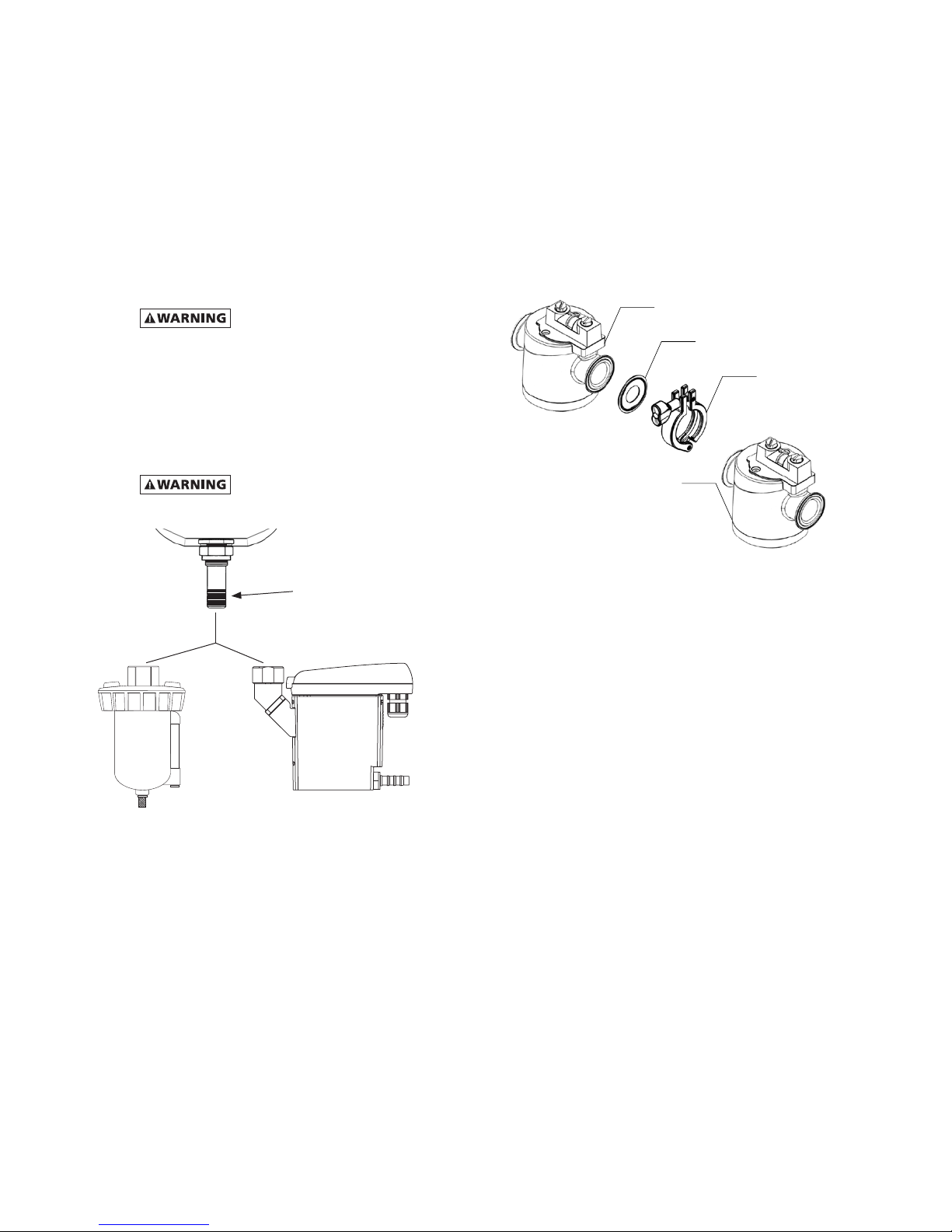
F.
Connector Clamps
(1) Aligntheclampgasketwiththeoutletange
onFilter#1makingsureitsiscenteredonthe
angegroove.
(2) Align the inlet ange from Filter #2 with the
clampgasketandFilter#1.
(3) Opentheclampassemblyandcenteritbetween
thetwolters.
(4) Closetheclampassemblyandtightenthewing
nutcompressingthegasketbetweenthetwo
lters.
Filter #1
Filter #2
Clamp
Clamp Gasket
Figure 1.4

5
2.0 Operation
Do not operate filter at pressures in
excessofMaximumWorkingPressureindicatedonSerial
NumberTag.
NOTE:MaximumOperatingTemperature-150°F(66°C).
Liquidltrationabove120°F(49°C)isnotrecommended
sincethereistypicallyoilpresentinavaporstatewhich
passesthroughthelterandcondensesdownstream.
NOTE:GradeC3-Ifoperatedabove100°F(38°C)may
experience less than 1000 hours of life because of
greateroilvaporcontent.
A.
Liquid Draining - Grades S3, P3, H3, and U3
NOTE: Collected liquids must be removed to ensure
properoperation.
NOTE: Depressurize slowly, to avoid filter element
damage.
1. ManualDrain-Turntotheright(clockwise)toopen
andtotheleft(counterclockwise)toclose.
2. AutomaticDrain-Liquidswillautomaticallydischarge
whensufcientaccumulationoccurs.
a) InternallyMountedAutoDrains-Thesedrains
maybemanuallydrainedbyturningtotheright
(clockwise) to open and to the left (counter-
clockwise)toclose.
NOTE:Manuallydraininternalautodrainsdailytoverify
drainfunction.
Figure 2.1
OPEN ( TO RIGHT )
B.
Operational Checkpoints
All Grades
Checkow,pressure,andtemperaturetomakecertain
lterisbeingoperatedwithindesignconditions.
Grades S3, P3, H3, and U3
Checkpressuredropacrossthelter
1. Pressuredifferentialinexcessof4.3psid(0.3bar)
- pressure indicator in red area - indicates that
thelterelementshouldbereplaced.Reference
page8,Figure3.3forgaugescaledetail.
NOTE:Elementshouldbechangedannuallyorwhen
indicatorchangestored,whicheveroccursrst.
NOTE: Pressure drop should never exceed 50psi
(3.4bar).
2. Checkforsuddenreductioninpressuredrop.This
mightindicate:
a. Possibleleakacrosselemento-ringseal.
b. Leak through the element due to physical
damage.
Grades S3, P3, H3, and U3
1. Checkto seethat lterisinstalled levelto insure
properdrainage.
2. Checkthatmanualdrainsaredrainedperiodically
orthatautomaticdrainsarefunctioning.
Grade C3 (Adsorber filter)
1. Checkforanoillikesmellbyopeningthemanual
valve.Ifanoilysmellexists,thefollowingshouldbe
checked:
a. Filterelementadsorptioncapacityexhausted.
b. Leakacrosselemento-ringseal.
c. Leakthroughelementduetophysicaldamage.
d. Presenceofliquidsbecauseoflackoforfailure
ofprelters.
e. Flow,pressureandtemperaturesoutsidedesign
conditions.
f. Presenceofgaseousimpuritieswhichcannot
beadsorbed.
Methane, carbon monoxide, carbon
dioxideandvariousinorganicgasescannotberemoved
byanactivatedcarbonlter.

6
Table 1 -
Maximum Flow @100 psig [6.9 bar]
Housing scfm
[nm3/h]
302 20
[34]
303 35
[59]
304 50
[85]
306 75
[127]
307 103
[175]
308 157
[267]
310 257
[437]
311 360
[612]
312 401
[681]
313 584
[993]
314 775
[1317]
315 1030
[1750]
316 1200
[2039]
317 1500
[2549]
Table 2 -
Air Flow Correction Factor
Inlet
Pressure
psig
20 30 40 60 80 100 120 150 200 250
bar
1.4 2.1 2.8 4.1 5.5 6.9 8.3 10.3 13.8 17.2
Correction Factor
0.30 0.39 0.48 0.65 0.83 1.00 1.17 1.44 1.87 2.31
C.
Flow Capacity
Maximum air ow for the various lters at 100psig
(6.9bar)isindicatedinTable1.Todeterminemaximum
airowsatinletpressuresotherthan100psig(6.9bar),
multiply flow from Table 1 by air flow correction
factorfromTable2thatcorrespondstotheminimum
operatingpressureattheinletofthelter.
NOTE:Filtersshouldnotbeselectedbypipesize.Select
usingowrateandoperatingpressureonly.

7
3.0 Maintenance
A.
When to Replace Filter Element
NOTE:GradesS3,P3,U3,H3,C3-completeelementis
replaced;
1. GradesS3,P3,U3,H3
a. Operating pressure drop: As lter becomes
liquid loaded (wetted), pressure drop will
increase. Further pressure drop occurs as
elementloadswithsolidparticles.
FOR MAXIMUM FILTRATION EFFICIENCY, REPLACE
ELEMENT WHEN PRESSURE DROP REACHES 4.3PSID
(0.3BAR) (INDICATOR IN RED AREA) OR ANNUALLY,
WHICHEVEROCCURSFIRST.
NOTE: Pressure drop may temporarily increase when
ow is resumed after ow stoppage. Pressure drop
shouldreturntonormalwithinonehour.
2. GradeC3-Oilvaporremovallter
a. Adsorption capacity - 1000 hours at rated
capacity.Elementlifeisexhaustedwhenodor
canbedetecteddownstreamofthelter.
B.
Procedure for Element Replacement
WARNING: THIS FILTER IS A PRESSURE CONTAINING
DEVICE.DEPRESSURIZEBEFORESERVICING.Iflterhas
notbeendepressurizedbeforedisassembly,anaudible
alarmwillsoundwhenthebowlbeginstoberemoved
fromthehead.Ifthisoccurs,stopdisassembly,isolate
andcompletelydepressurizelterbeforeproceeding.
1. Isolatelter(closeinletandoutletvalvesifinstalled)
orshutoffairsupply.
2. Depressurizelterbyslowlyopeningmanualdrain
valve.
3. Removebowl.
a. Unscrew the bowl from the lter head using
hand, strap wrench or C spanner. Pull bowl
straightdown.
4. Cleanlterbowl.
5. Replaceelement.
a. Replacingcompleteelement.
1) Pulloffoldelementanddiscard.
2) Makecertainthattheoldandnewelement
havethe same part number andthe end
capsarethesamecolor.
3) Wipe the wall inside the filter head to
removeanydirt.
4) Lubricate the new element o-ring on the
elementtopcap.
5) Aligntheslotintheelementtopcapwith
theprojectioninsidethelterhead.
Figure 3.1
6) Insert the element into the head making
sure the element slot and the projection
insidethelterheadremainaligned.
NOTE:Handleallelementsbybottomendcap
only.
6. Replace housing o-ring (located at the top of
thelter bowl) if needed. Make certaino-ring is
generouslylubricated(Uselubricantprovided).
7. Reassemblebowltohead.
NOTE:Threadedbowltoheadconnection,generously
lubricate threads with a high grade/temperature
lubricant150°F(66°C).(Uselubricantprovided)
C.
Auto Drain Mechanism
It is recommended that drain mechanism be
replacedannually.
Projection
ElementSlot
O-Ring

8
Dimensions and Weights
Model
Number
Max. Flow
@ 100 psig
(6.9 bar)
Connections Dimensions Weight
'A'
Width
'B'
Height
'C'
Height
'D'
Bowl Clearance
scfm nm3/h NPT in mm in mm in mm in mm lbs kg
302 20 34 1/4" 4.5 114 8.1 206 6.8 173 4.0 102 1.8 0.8
303 35 59 3/8" 4.5 114 8.1 206 6.8 173 4.0 102 1.8 0.8
304 50 85 1/2" 4.5 114 9.9 252 8.5 216 4.0 102 1.9 0.9
306 75 127 3/4" 5.2 132 10.3 262 8.7 221 5.0 127 3.1 1.4
307 103 175 3/4" 5.2 132 10.3 262 8.7 221 5.0 127 3.1 1.4
308 157 267 1.0" 5.2 132 12.8 325 11.7 297 5.0 127 3.5 1.6
310 257 437 1.5" 7.9 201 13.3 338 10.9 277 7.0 178 8.4 3.8
311 360 612 1.5" 7.9 201 17.1 434 14.7 373 7.0 178 9.9 4.5
312 401 681 2.0" 7.9 201 22.3 564 19.9 506 7.0 178 11.6 5.3
313 584 993 2.5" 9.1 231 24.9 633 21.7 551 8.0 203 18.6 8.4
314 775 1,317 2.5" 9.1 231 24.9 633 21.7 551 8.0 203 18.6 8.4
315 1,030 1,750 2.5" 9.1 231 32.2 818 28.9 734 8.0 203 27.7 12.6
316 1,200 2,039 3.0" 9.1 231 32.2 818 28.9 734 8.0 203 27.7 12.6
317 1,500 2,549 3.0" 9.1 231 42.7 1,085 39.4 1,001 8.0 203 41.3 18.7
NOTE:DimensionsandWeightsareforreferenceonly.Requestcertieddrawingsforconstructionpurposes.
Figure 3.2
Figure 3.3
Differentialpressuregaugeandslideindicator–
changeelementwhenindicationisintheredzone.
INLET OUTLET
CLEARANCE
FOR SERVICING
'D'
'C'
1" (26 mm)
'B'
'A'
INLET OUTLET
'A'
'D'
'C'
'B'
CLEARANCE
FOR SERVICING
2.3" (58.4 mm)

9
SERVICE DEPARTMENT: (724) 746-1100
WARRANTY
Themanufacturerwarrantstheproductmanufacturedbyit,whenproperlyinstalled,operated,applied,andmaintained
inaccordancewithproceduresand recommendationsoutlinedinmanufacturer’s instructionmanuals,tobefreefrom
defectsinmaterialandworkmanshipforaperiodofone(1)yearfromdateshipmenttothebuyerbythemanufacturer
ormanufacturer’sauthorizeddistributorprovidedsuchdefectisdiscoveredandbroughttothemanufacturer’sattention
withintheaforesaidwarrantyperiod.
Themanufacturerwillrepairorreplaceanyproductorpartdeterminedtobedefectivebythemanufacturerwithinthe
warrantyperiod,providedsuchdefectoccurredinnormalserviceandnotasaresultofmisuse,abuse,neglectoraccident.
Normalmaintenance itemsrequiringroutine replacementarenotwarranted.The warrantycovers parts and laborfor
thewarrantyperiod.Repairorreplacementshallbemadeatthefactoryortheinstallationsite,atthesoleoptionofthe
manufacturer.Anyserviceperformedontheproductbyanyoneotherthanthemanufacturermustrstbeauthorizedby
themanufacturer.
Unauthorizedservicevoidsthewarrantyandanyresultingchargeorsubsequentclaimwillnotbepaid.Productsrepaired
orreplacedunderwarrantyshallbewarrantedfortheunexpiredportionofthewarrantyapplyingtotheoriginalproduct.
Theforegoingistheexclusiveremedyofanybuyerofthemanufacturer’sproduct.Themaximumdamagesliabilityofthe
manufactureristheoriginalpurchasepriceoftheproductorpart.
THEFOREGOINGWARRANTYISEXCLUSIVEANDINLIEUOFALLOTHERWARRANTIES,WHETHERWRITTEN,ORAL,ORSTATUTORY,
ANDISEXPRESSEDINLIEUOFTHEIMPLIEDWARRANTYOFMERCHANTABILITYANDTHEIMPLIEDWARRANTYOFFITNESSFOR
APARTICULARPURPOSE.THEMANUFACTURERSHALLNOTBELIABLEFORLOSSORDAMAGEBYREASONOFSTRICTLIABILITY
INTORTORITSNEGLIGENCEINWHATEVERMANNERINCLUDINGDESIGN,MANUFACTUREORINSPECTIONOFTHEEQUIPMENT
OR ITS FAILURE TO DISCOVER, REPORT, REPAIR, OR MODIFY LATENT DEFECTS INHERENT THEREIN. THE MANUFACTURER,
HISREPRESENTATIVEORDISTRIBUTORSHALLNOTBELIABLEFORLOSSOFUSEOFTHEPRODUCTOROTHERINCIDENTALOR
CONSEQUENTIALCOSTS,EXPENSES,ORDAMAGESINCURREDBYTHEBUYER,WHETHERARISINGFROMBREACHOFWARRANTY,
NEGLIGENCEORSTRICTLIABILITYINTORT.
Themanufacturerdoesnotwarrantanyproduct,part,material,component,oraccessorymanufacturedbyothersand
soldorsuppliedinconnectionwiththesaleofmanufacturer’sproducts.
AUTHORIZATION FROM THE SERVICE DEPARTMENT IS NECESSARY BEFORE MATERIAL
IS RETURNED TO THE FACTORY OR IN-WARRANTY REPAIRS ARE MADE.

300 SERIES
Compressed Air Filters
Models 302 (grade) through 317 (grade)
SPX
1000 Philadelphia Street
Canonsburg, PA 15317-1700 U.S.A.
P: (724) 745-8647
F: (724) 745-4967
www.deltech-spx.com
Improvements and research are continuous at SPX.
Specifications may change without notice.
ISSUED 01/2014 Form No.: 3259480 Revision: C
COPYRIGHT ©2014 SPX Corporation
Table of contents
Other SPX Water Filtration System manuals


Popular Water Filtration System manuals by other brands

Crystal Quest
Crystal Quest CQE-RC-00808 Installation and operation guide

RZ AIRflow
RZ AIRflow 10048 user guide

3M
3M Aqua-Pure AP902 Installation and operating instructions

AquaCo
AquaCo SYS -ROCOMP manual

Riello
Riello BAG2 MIX CLIMA INSTRUCTIONS FOR THE INSTALLER AND THE TECHNICAL ASSISTANCE SERVICE

SMC Networks
SMC Networks FH100 Series Operation manual


