Watts BT-TH02 RF User manual
Other Watts Thermostat manuals
Watts
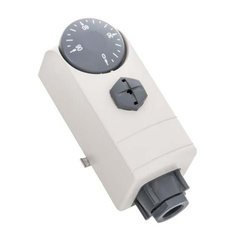
Watts WTC-ES User manual
Watts
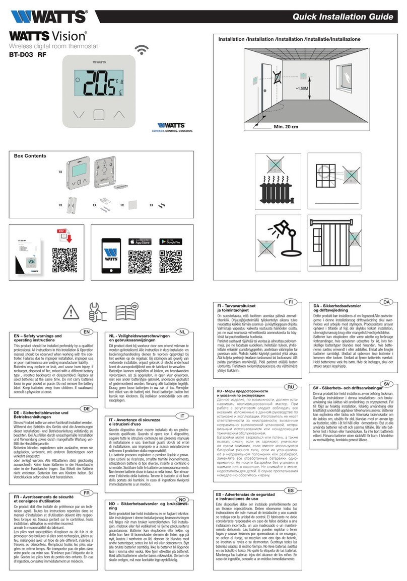
Watts Vision BT-D03 RF User manual

Watts
Watts WTC-ES User manual
Watts
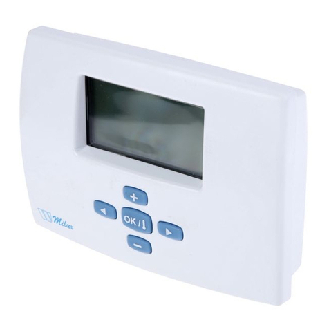
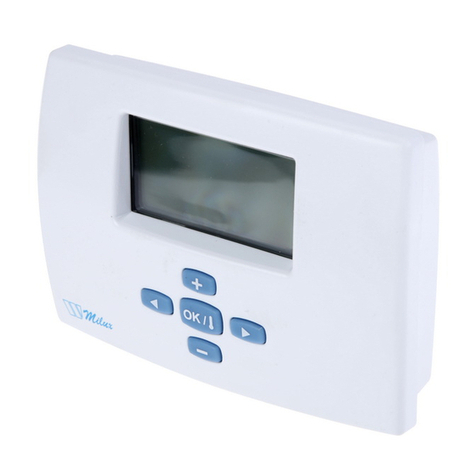
Watts Milux Star User manual
Watts
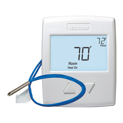
Watts Radiant 519 User manual
Watts
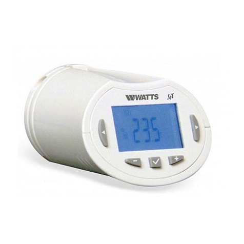
Watts BT-TH02 RF User manual
Watts
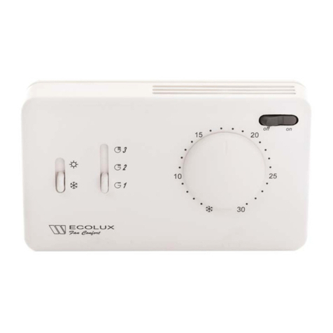
Watts ECOLUX Fan Confort 4T User manual
Watts
Watts tekmar 562 User manual
Watts
Watts BT-DPRF-02 User manual

Watts
Watts tekmar Invita Installation instructions
Watts
Watts BT-A RF User manual
Watts
Watts W561 User manual
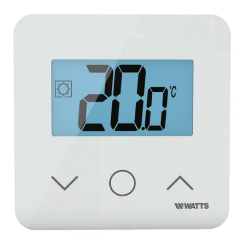
Watts
Watts Vision Wired WT-D03 User manual

Watts
Watts BT-TH02 RF User manual

Watts
Watts BT-DRF User manual
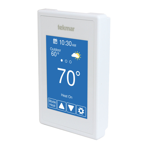
Watts
Watts Tekmar WiFi Thermostat 561 User manual
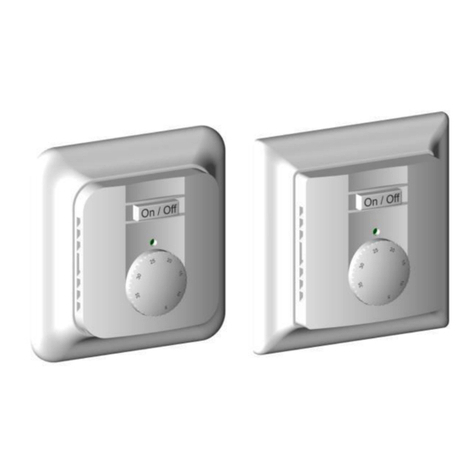
Watts
Watts Wattstemp 740 User manual
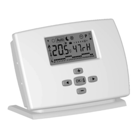
Watts
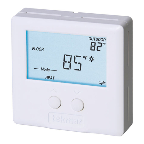
Watts MILUX-HY User manual
Watts
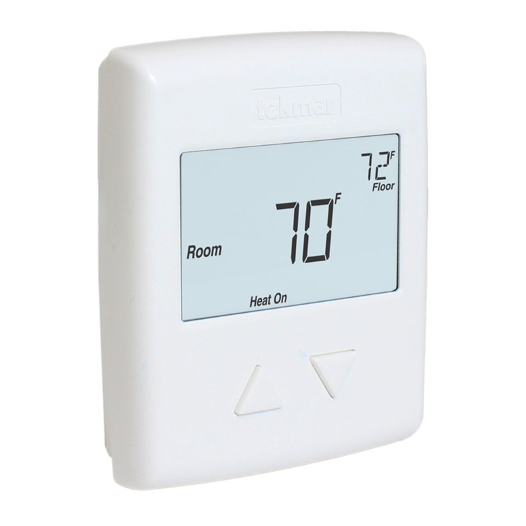
Watts tekmar tekmarNet 2 User manual
Watts
Watts tekmar 518 User manual
Popular Thermostat manuals by other brands

Charmeg
Charmeg MP-R user manual

dixell
dixell WING XW40LS Installing and operating instructions

Network Thermostat
Network Thermostat NetX X7C-WIFI Installation and programming manual

Radio Thermostat
Radio Thermostat CT80 Operation guide

HAI
HAI Omnistat RC-120 installation manual

Lennox
Lennox iComfort E30 Installation and setup guide

Lux Products
Lux Products PSD011Ba Installation and operating instructions

Computherm
Computherm Q20 operating instructions

Heatmiser
Heatmiser neoStat user manual

Mars
Mars HEAT CONTROLLER IR Wireless Thermostat user manual

LUX
LUX LP0511D user manual

Saswell
Saswell SAS920XWHB-7-S-RF User manual and warranty card


