squarespace LEI-4361DMX User manual
ISO9001:2000
CERTIFIED
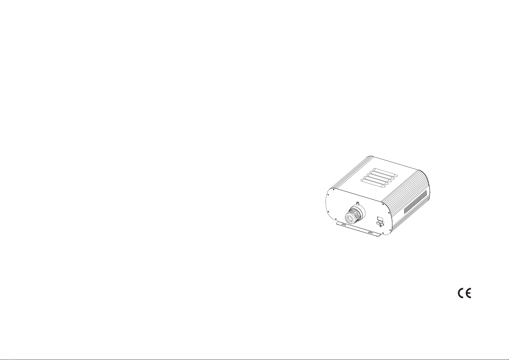
M O D E L : L E I - 4 3 6 1 D M X
LED
LIGHT
ENGINE
MENU
UP
DOWN
MIC
LIGHT ENGINE
USER MANUAL
Accessories:
Fiber Connector .............................. PC1
Wireless Remote Controller...............1 PC (Optional)
User Manual .............................. . . . . . . 1 PC
Signal Cable ....................................1 PC (for DMX machine only)

CHAPTER 1 LEI-4361DMX
1
Safety Instruction
1. Make sure the Light Engine and Power Source have the same voltage;
2. Keep out of rain or moist area to avoid shock hazards;
3. Avoid to use at high ambient temperature ( >40℃);
Welcome to use Minar professional LED light engine, LEI-4361DMX. Please read
the manual carefully before turning on the power. If you have any questions
concerning the operation or maintenance, please contact your wholesaler.
LIGHT ENGINE
USER MANUAL
1. Technical Data
2. Installation dimension of light engine(see Fig.1):
Life of LED : 50000H
Standard aperture: Φ28mm/Φ24mm/Φ20mm (Optional:Φ30mm Max)
3
Size: 291×264×135mm
Gross Weight: 7.0Kg
Voltage: 110V~230V AC
Power: 160W
Color : RGBW
Light Source: 1-4X36W LED
3. Light Engine Setup
There are three control modes of LEI-4361DMX, the DMX512 protocol light engine:
* DMX512 Signal Control Mode: DMX512 Signal is received from a DMX512 console.
* Master/Slave Mode: One Light Engine is set as Master, while the rest light engines
are set as Slave. Master sends control signal to slave so that all the machines run the
program synchronously.
* Audio Control Mode: Light engines are controlled by sound.
135
11 0
LED LIGHT ENGINE
MENU
UP DOWN
MIC
AERI AL
275
291
26 4
Fixing Flange
Menu(UP,DOWN)
Fan
Fig. 1
FUSEPOWER
SWITCH
Fuse
Power switch
Power cable
DMX IN
DMX OUT
Aerial (optional)
DMX IN
DMX OUT
2
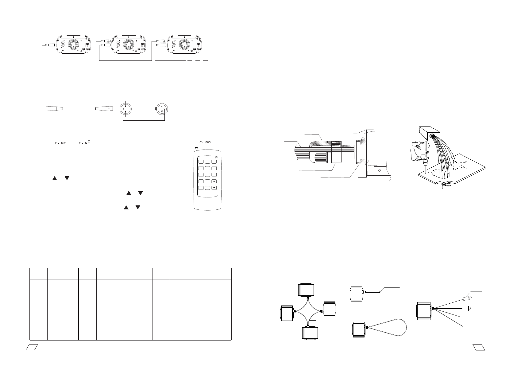
(3)The connection of DMX Signal Control Mode(See Fig. 2): Fig. 2
DMX512 Console
Slave 2 Slave 3
Slave 1
AERIA L
FUSEPOWER
SWITCH
DMX IN
DMX OUT
AERIA L
FUSEPOWER
SWITCH
DMX IN
DMX OUT
AERIA L
FUSEPOWER
SWITCH
DMX IN
DMX OUT
(1) DMX 512 signal control mode:
DMX address setup:
When a DMX512 console is used, all the light engines, LEI-4361DMX, in the group should be
set up as slave machines with DMX address of “001".
DMX Channels: 8 Channels
CH1:Red CH2:Green CH3:Blue CH4:White CH5:Speed (16 Tiers)
CH6:Dimmer(8 Tiers) CH7: Strobe (8 Tiers) CH8: Twinkle(8 Tiers)
(2) Master/Slave mode:The settings of Master/Slave light engine:
Notice:
REMARKS
Adjusting of brightness ,total 8 levels :d.00,d.10,d.20,
d.35,d.50,d.70,d.85,d.99.(d.99.means100% brightness)
Setting of twinkle wheel speed, total 8 levels:
0RPM,1RPM,2RPM,3RPM,4RPM,5RPM,8RPM,12RPM
22 preset programs(see attached list,when it
display “P.XX”,press “UP/DOWN” to get into
this menu)
PS.1-PS.2 are audio control programs (when it
display “PS.X”,press “UP/DOWN” to get into
this menu)
Setting of program running speed, total 8 levels:
0S,1/4S,1/2S,1S,2S,3S,5S,8S
DESCRIPTION OF FUNCTIONS
DMX address, “001”-“505” are available
MENU
No.
1
2
3
4
5
6
Slave
DMX Receiver
MASTER
STATUS
r.on: Remote control is on,
r.oF: Remote control is off.
. .
. .
. .
. .
. .
. .
1.Hold and press the two buttons at
the same time for 3 seconds to
unlock the menu for setting up.
2. Hold and press the button “UP”,
at the same time to press the
button“DOWN” to switch the
menu.Then release both bottons.
3. Press either button of “UP” or
“DOWN” to choose the right
parameter.
4. After 60 seconds, the data will be
saved and the menu locked.
5. When the display is on, the dot
next to the third digit will flash
if there is any DMX signal coming
in.
1 If you need Master/Slaves to change color synchronously, please set all of slaves as “001”;
2 If you need Master/Slaves to chase to change color, please set the first slave machine as
“009”, the second one as “017” and so on (add “8” one after another) ..
4 options of DMX channels numbers available when
control led by a DMX console. :1 channel (Colors);
: 4 channels (Ch1:R,CH2:G,CH3:B,CH4:W);
: 5 channels (Ch1:R,CH2:G,CH3:B,CH4:W;
CH5:Wheel speed); : 8 channels by default.
7
*
Holding button “UP” and press “DOWN” continuously until the display shows three digits
between 001-505 in editting mode, press the button “UP” or “DOWN” to select the address.
Attached Table:
Pro. No. Pro. No. Pro. No.
P.00
P.01
P.02
P.03
P.04
P.05
P.06
P.07
P.08
P.09
P.1 0
P.1 1
P.1 2
P.1 3
P.1 4
P.1 5
No Light
White
Red
Green
Blue
Purple
Yellow
Sky-B
7 colors skip
6 colors skip
3 colors skip
7 colors fade
6 colors fade
3 colors fade
7 colors skip+7 colors fade
6 colors skip+6 colors fade
Function Function
7 colors skip & chase
6 colors skip & chase
3 colors skip & chase
7 colors fade & chase
6 colors fade & chase
3 colors fade & chase
3 colors skip & audio control
3 colors skip & audio control
P.1 6
P.1 7
P.1 8
P.1 9
P.20
P.21
PS.1
PS.2
Function
Fig.5
RC-15
Wireless Remote Controller
3
6
9
2
5
8
0
SP
DIM
PRO
1
4
7
4. Wireless remote controller (See Fig.5):
Press the two buttons “UP” / “DOWN” besides the Display at the same time. When it
displays , press either button of “UP” / “DOWN” to show “ ”
(status of remo tecontrol). The remote function is on.
15-Key Remote Controller:
(1) Program Selection: Press “PRO”, then press the digit key on the
controller, “00”-“23”, to choose the desirable program, or you can
use “ ”,“ ” to select.
(2) Dimming: Press the key “DIM”, then press “ 0 ”-“ 7 ” to have the
desirable brightness, or you can use “ ”,“ ” to adjust.
(3) Speed of the color wheel:Press the key “SP”, then press “0”-”7”
to adjust the speed, or you can use “ ”,“ ” to adjust.
“ ” or “ ”
Notice:
① Address code of slave (machines) are not adjustable under remote control status.
② When you are selecting the program, only double-digit numbers on the controller
are recognizable (e.g. 00, 01, 02...).
3
(4)The connection of Master/Slave Control Mode(See Fig. 3):
Fig. 3
(5)Signal cable and connector (See Fig.4):
2
Signal cable should be 2×0.5mm audio cable.
PIN2: SIGNAL-
PIN3: SIGNAL+
PIN1: GND
3
1
2
Fig.4
1
2
3
4
3. Commonly used installation method of fiber optic cable:
(1) Side Lighting Fiber Optic:
(see Fig.3).
2.Installation of the end part of the Multi-String fiber optic:
(1) Drill holes on the installing board according to the design. Then insert the fiber optic
(2) Insert the finished Fiber Connector into the Fixing Flange and screw tightly the Screw.
string into holes and fix it with epoxy glue. Trim the end of the fiber string to be flush
with the board or at a required length. Fasten the other end of the fiber string to a
harness and insert the harness into PG Connector and Fiber Connector. Apply the
hot knife to cut fiber end flush with the Fiber Connector.
(see Fig.2).
1. Connecting the fiber optic with Light Engine:
Solid Core fiber optic(see Fig. 1):
(1) Cut the fiber to the specified length. The cross section should be vertical to the
fiber and keep clean and smooth.
(2) Peel off 50-100mm of the PVC jacket of the fiber optic cable (not necessary if
there is no PVC jacket). Be careful not to hurt the fiber optic.
(3) Unscrew the PG Connector and insert the fiber optic cable into the PG Connector
and Fiber Connector until the end of the cable is flush with the Fiber Connector.
Screw tightly the PG Connector.
(4) Insert the finished Fiber Connector into the Fixing Flange, screw tightly the Screw.
Single Lighting
End Plug
Light Engine
Side Glow
Fiber Optic
Single Set Double Lighting
Multi Sets Double Lighting
Fig.3
(2) End Lighting Fiber Optic:
(see Fig.4).
With End Piece
Fig.4
Fiber Optic
PG Connector Front Case
Fiber Connector
Fixing Flange
Fig. 1 Fig. 2
Chapter 2 Installation of Fiber Optic
Slave 1 Slave 2
Master
AERIA L
FUSEPOWER
SWITCH
DMX IN
DMX OUT
AERIA L
FUSEPOWER
SWITCH
DMX IN
DMX OUT
AERIA L
FUSEPOWER
SWITCH
DMX IN
DMX OUT
Popular Lighting Equipment manuals by other brands

Mosaic
Mosaic BWL-0625 operating instructions

Luminaire led
Luminaire led ESF18 installation guide

Electronics Diversified
Electronics Diversified T-12 user manual

Griven
Griven Powershine MK2 S instruction manual

JB Systems
JB Systems Matrix LED Operation manual

Lightolier
Lightolier Lytespan 23MHRF specification


