SRC 3000 User manual

iii

SRC Ranger Converter 3000
2
The information in this document may be trademarks or registered trademarks of their respective companies.
All rights reserved. Neither the whole nor any part of the information in this publication may be reproduced in any material form except
with the written permission of S-Rain Control A/S.
This publication is intended only to assist the reader in the use of the Ranger Converter 3000. S-Rain Control A/S shall not be liable
for any loss or damage arising from the use of any information in this publication, or any error or omission in such information, or
any incorrect use of the product.
Address:
258-230-0003/A

iii
Contents
Chapter 1. Introduction ....................................................................................................................................................5
1.1. Target group .....................................................................................................................................................5
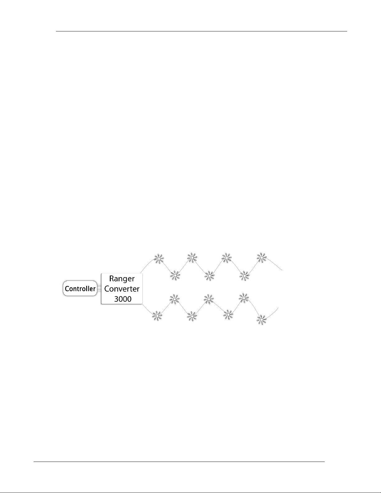
1.2. The Two-wireTechnology..................................................................................................................................5
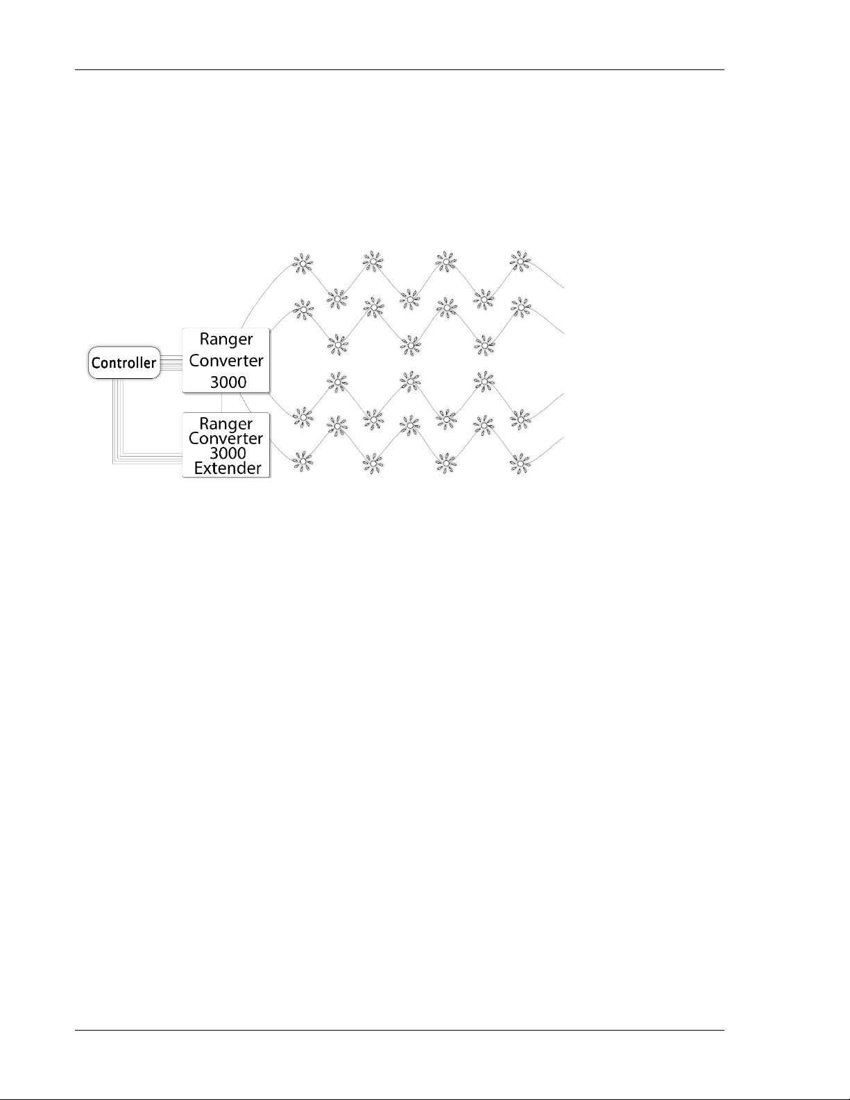
1.3. The Ranger Converter 3000Extender .............................................................................................................5
Chapter 2. Technical Specifications ................................................................................................................................3
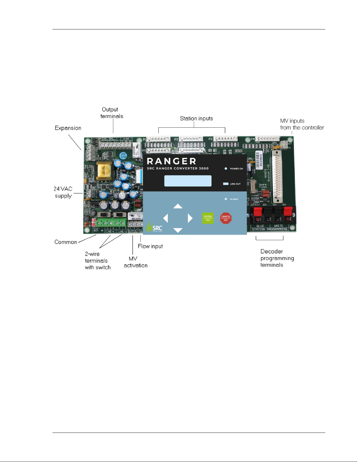
2.1. The Ranger Converter 3000Board ..................................................................................................................3
2.1.1.
Expansion terminal...............................................................................................................................3
2.1.2.
Output terminals ...................................................................................................................................3
2.1.3.
Station inputs........................................................................................................................................4
2.1.4.
Master Valve terminal............................................................................................................................4
2.1.5.
24VAC supply........................................................................................................................................4
2.1.6.
Common ...............................................................................................................................................4
2.1.7.
Two-wire terminals................................................................................................................................5
2.1.8.
Master valve activation.........................................................................................................................5
2.1.9.
Flow input .............................................................................................................................................5
2.1.10.
Decoder programming terminals.........................................................................................................5
2.1.11.
Remote activation................................................................................................................................5
2.3.The Ranger Converter 3000 Extender..............................................................................................................5
Chapter 3. System Installation.........................................................................................................................................7
3.1. Physical Installation..........................................................................................................................................7
3.1.1.
Installing the Ranger Converter 3000 Board in theCabinet .................................................................8
3.1.2.
Connecting the Ranger Converter 3000 to 24VAC andGround ...........................................................9
3.1.3.
Connecting the Master Valve ..............................................................................................................10
3.1.4.
Connecting the Main Controller Outputs toRanger Converter 3000 Station Inputs............................11
3.1.5.
Connecting the Flow Input and Flow Output ......................................................................................12
3.1.6.
Connecting the Load Output ..............................................................................................................13
3.1.7.
Connecting the Two-wire.....................................................................................................................14
3.1.8.
Connecting Decoders for Programming .............................................................................................15
3.1.9.
Connecting the Ranger Converter 3000 Extender to the Board..........................................................16
3.2. Ranger Converter 3000 Installation Diagram.................................................................................................17
Chapter 4. Operating the Ranger Converter 3000 ........................................................................................................18
4.1. The Display ....................................................................................................................................................18
4.2. Buttons and LEDs ..........................................................................................................................................18
4.3. Navigating the Menus of the Ranger Converter 3000....................................................................................19
Chapter 5. Running the Ranger Converter 3000...........................................................................................................20
5.1. The Main View................................................................................................................................................20
5.2. Displaying Controller Status...........................................................................................................................21
5.2.1.
Displaying the Flow Input ...................................................................................................................21
5.2.2.
Displaying the Number of Active Stations ..........................................................................................21
5.2.3.
Displaying the AlarmStatus ................................................................................................................21
Chapter 6. Configuring the Ranger Converter 3000......................................................................................................25
6.1. Setting Up the Ranger Converter 3000System .............................................................................................25
6.2. Programming Decoders .................................................................................................................................25
6.3. Setting the Master Valve Override..................................................................................................................26
6.4. Adjusting the Power Levels............................................................................................................................26
6.4.1.
Adjusting the Station Power................................................................................................................27
6.4.2.
Adjusting the Master Valve Power.......................................................................................................28
6.4.3.
Resetting Station Power .....................................................................................................................28
6.4.4.
Checking the Number of Active Stations ............................................................................................29
6.5. Resetting Data................................................................................................................................................29
Chapter 7. Troubleshooting from the Ranger Converter 3000......................................................................................31
7.1. Testing Stations..............................................................................................................................................31
7.1.1.
Testing Individual Stations ..................................................................................................................31
7.1.2.
Running the ElectricalTest .................................................................................................................31

SRC Ranger Converter 3000
2
7.1.3.
The Built-in Short FindingTest............................................................................................................32
7.2. Testing the Two-wire Path ...............................................................................................................................33
7.3. Increasing Station Power ...............................................................................................................................34
Chapter 8. Troubleshooting in the Field ........................................................................................................................35
8.1. Checking Power and Current Readings.........................................................................................................35
8.1.1.
Problems on theTwo-wire...................................................................................................................37
8.2. Dealing with Unstable Stations ......................................................................................................................38
8.3. Dealing with Failing Stations..........................................................................................................................39
8.3.1.
A Single Station Fails .........................................................................................................................39
8.3.2.
Several Stations Fail...........................................................................................................................41
8.4. When there is a Short Circuit in the Field......................................................................................................42
8.4.1.
Using a Clampmeter...........................................................................................................................43
8.4.2.
Locating the Short ..............................................................................................................................43
Appendix A. Flashing new Firmware to the Ranger Converter 3000 System...............................................................47
A.1. Requirements.................................................................................................................................................47
A.1.1.
Installing the USB driver.....................................................................................................................47
A.2. Flashing new Firmware to the Ranger Converter 3000 Board.......................................................................47
A.3. Flashing New Firmware to the Ranger Converter 3000 Extender .................................................................49

iv
Chapter 1. Introduction
The Two-wire Decoder Interface (Ranger Converter 3000) is designed to integrate conventional systems
with proven two-wire technology. The Ranger Converter 3000 allows clients in the landscape irrigation
industry to retrofit their existing controllers systems. Not only does this provide a cost-efficient solution, it also
ensures the clients' vendor independence by allowing them to use the main controller of their preferred
choice. The Ranger Converter 3000 will enable any conventional irrigation system for the two-wire
technology.
1.1.
Target group
This manual provides instructions intended for the setup and management of the Ranger Converter 3000
and therefore is primarily intended for installation and maintenance people.
1.2.
The Two-wireTechnology
Once set up, the communication between the Ranger Converter 3000 system and the stations happen over a
two-wire path. Depending on the signal from the controller, the stations each activate or deactivate a valve.
Via the Ranger Converter 3000 board, the controller signals to the stations based on configurable schedules,
eliminating the need for human interaction when the park, garden, or other surroundings need watering.
The Ranger Converter 3000 uses two-wire transmission technology to tell the stations when to act. This
means that instead of laying out a cable to each individual valve, just one or two cables are laid out, and
the stations all connect to the same cable(s).
The two-wire technology has several obvious advantages over a conventional system:
• Ease of installation: You are handling one roll of wire.
• Ease of expansion: When you need to add a station in the field, you don't have to dig in a new cable and
risk damaging the existing web of cables in the ground. You simply attach the new station to the existing
cable.
• Cost reduction: You save money on expensive copper cable. Typically as much as 80 percent compared
to traditional cabling.
1.3.
The Ranger Converter 3000 Extender
The Ranger Converter 3000 system may be expanded with the Ranger Converter 3000 Extender - an
interface board like the Ranger Converter 3000 itself but without the display and control panel. By adding
the Ranger Converter 3000 Extender to your Ranger Converter 3000 system you may increase the capacity

The Ranger Converter 3000 Extender
2
with up to another 48 stations and an additional master valve. The master valve operates in parallel with
the existing master valve input. The Ranger Converter 3000 Extender connects to the Ranger Converter
3000 system via the expansion terminal on the Ranger Converter 3000 board.
The Ranger Converter 3000 Extender is depicted in Chapter 2: Technical Specifications.
For information on connecting the Ranger Converter 3000 Extender to the Ranger Converter 3000 Board, turn to
Chapter 3: System Installation.

3
Chapter 2. Technical Specifications
2.1.
The Ranger Converter 3000 Board
The core of your Ranger Converter 3000 system is the Ranger Converter 3000 Board that manages the
integration between your main controller and the stations. In the sections below you will find a description of
the layout of the Ranger Converter 3000 Board and its input and output terminals.
2.1.1.
Expansion terminal
Use the expansion terminal to connect the optional Ranger Converter 3000 Extender, enabling flow access
for up to 48 additional stations and a master valve. For more information on connecting the Ranger Converter
3000 Extender and the Ranger Converter 3000 Board, turn to Section 3.1.9, “Connecting the Ranger
Converter 3000 Extender to the Ranger Converter 3000 Board”[16].
2.1.2.
Output terminals
Use the output terminals to connect the flow output(s), and load.

4
Station inputs
Flow output
Pulses are output at a frequency similar to the frequency that is read from the first sensor decoder.
Maximum is 200 pulses / sec. The pulses are send with a 50/50% duty cycle.
Aux output
This is the same as Flow output, but for the second sensor decoder.
Alarm
This relay is activated if any decoder is enabled. It can be used to connect a load (resistor or coil) if the controller
requires a load.
2.1.3.
Station inputs
These inputs are used for connecting up to 48 stations in the conventional system to the Ranger
Converter 3000. All inputs react on a 24VAC input. Use the following connection scheme:
Table 2.1. Station connection scheme (from left to right)
P1
Station 1 to Station 8
P2
Station 9 to Station 16
P3
Station 17 to Station 24
P4
Station 25 to Station 32
P5
Station 33 to Station 40
P6
Station 41 to Station 48
1) If the maximum number of simultaneous stations in the system are active, and one of the active stations
is deactivated at the same time as a station with a higher number is activated, then the new station will not
be activated.
2.1.4.
Master Valve terminal
Use this input terminal to connect the master valve. The HOT is the 24VAC from the mains transformer. For
more information, turn to Section 3.1.3, “Connecting the Master Valve” [10].
2.1.5.
24VAC supply
Use this input to connect to the power supply 24VAC 50/60 Hz. Power consumption is up to 2A (in addition
to the main controller's electrical current. That is, the transformer must be rated at least 50 VA!). For more
information, turn to Section 3.1.2, “Connecting the Ranger Converter 3000 to 24VAC and Ground” [9].
2.1.6.
Common
Use this input to connect to the main controller's common and GND rod. For more information, turn to
Section 3.1.2, “Connecting the Ranger Converter 3000 to 24VAC and Ground” [9].

5
Two-wire terminals
2.1.7.
Two-wire terminals
LINE-1 and LINE-2 terminals are used for the actual two-wire connection. Each terminal is equipped with a
switch for disconnecting the line during troubleshooting. For more information, turn to Section 3.1.7,
“Connecting the Two-wire” [14].
Warning
While the Ranger Converter 3000 is running, a short on the two-wire will not clear the display
and thus it might still display active stations even if they are not active.
2.1.8.
Master valve activation
Use this terminal to connect a push button which may turn on the master valve when activated.This enables
you to manually activate the master valve. When activated, the master valve will remain turned on for a
specified number of hours. Pressing the push button quickly, when the master valve is on, will restart the
timer. A longer push (more than 3 seconds) will stop the master valve. For more information, turn to
Section 3.1.3, “Connecting the Master Valve” [10].
2.1.9.
Flow input
Input is not used. Instead flow is read via one or two sensor decoders on the 2-wire. These sensor
decoders must have address 50000 and 50001 respectively.
2.1.10.
Decoder programming terminals
These terminals are used when programming decoders. All wires on the decoder must be connected. Blue
wires to the left, white wires to the right. Section 3.1.8, “Connecting Decoders for Programming” [15].
2.1.11.
Remote activation
This feature is not implemented. Planned for a future release.
2.3.The Ranger Converter 3000 Extender
The Ranger Converter 3000 Extender is like the Ranger Converter 3000 Board itself but without the the
display and control panel. By adding the Ranger Converter 3000 Extender to your Ranger Converter 3000
system you may increase the capacity with up to another 48 stations and an additional master valve. The
master valve operates in parallel with the existing master valve input. The Ranger Converter 3000
Extender connects to the Ranger Converter 3000 system via the expansion terminal on the Ranger
Converter 3000 board.
For information on connecting the Ranger Converter 3000 Extender to the Ranger Converter 3000 Board,
turn to Section 3.1.9, “Connecting the Ranger Converter 3000 Extender to the Ranger Converter 3000
Board” [16].

The Ranger Converter 3000 Extender
6

7
Chapter 3. System Installation
This chapter provides information on connecting the various output and input terminals of your Ranger
Converter 3000 system.
3.1. Physical Installation
The physical installation of the Ranger Converter 3000 System involves the following procedures.
• Installing the Ranger Converter 3000 Board in the Cabinet
• Connecting the Ranger Converter 3000 to 24VAC and Ground
• Connecting the Master Valve
• Connecting the Main Controller Output to Ranger Converter 3000 Station Inputs
• Connecting the Flow Input and Flow Output
• Connecting the Alarm Output
• Connecting the Two-wire
• Connecting Decoders for Programming
• Connecting the Ranger Converter 3000 Extender to the Ranger Converter 3000 Board
In the following, each of these procedures are depicted in simple illustrations. Turn to the Ranger
Converter 3000 Installation diagram at the end of this chapter for a full overview.

8
Installing the Ranger Converter 3000 Board in the Cabinet
3.1.1.
Installing the Ranger Converter 3000 Board in the Cabinet
Depending on which main controller you use, installation may vary. Use four screws and a screwdriver to
mount the board. Note that standoffs are typically required, which isolates the underside of the circuit board
from the metal chassis. Ensure that the board is not shorted before applying power, or damage may occur.
The photo below shows an example installation of a Ranger Converter 3000 with a typical controller. Please
refer to the following sections for connecting the various terminals of the Ranger Converter 3000 Board.

9
Connecting the Ranger Converter 3000 to 24VAC and Ground
3.1.2.
Connecting the Ranger Converter 3000 to 24VAC and Ground
Using a flat head screwdriver connect the 24VAC terminals to the 120 V mains using a suitable transformer
(supplied by the customer). Also, to help secure your system against lightning, you must ensure that the
Ranger Converter 3000 is grounded. Refer to the illustration below and to the Ranger Converter 3000
Installation diagram at the end of this chapter.
Ranger Converter
3000 Board

10
Connecting the Master Valve
3.1.3.
Connecting the Master Valve
In terms of master valve connections, the Ranger Converter 3000 Board allows for the following:
• Connection of the master valve to the primary controller.
• Connection of a push button (supplied by the customer) for the manual activation of the master valve.
Using a flat screwdriver refer to the illustration below for master valve connections.
Ranger Converter
3000 Board

11
Connecting the Main Controller Outputs to Ranger Converter 3000 Station Inputs
3.1.4.
Connecting the Main Controller Outputs to Ranger Converter
3000 Station Inputs
Using a flat head screwdriver, connect the main controller's outputs to the Ranger Converter 3000
station inputs. Refer to the illustration below and to the Ranger Converter 3000 Installation diagram at
the end of this chapter.
Ranger Converter
3000 Board

12
Connecting the Flow Input and Flow Output
3.1.5.
Connecting the Flow Input and Flow Output
Using a flat head screwdriver, connect the flow output. Input is not used. Instead flow is read via one or two
sensor decoders on the 2-wire. These sensor decoders must have address 50000 and 50001 respectively.
Refer to the illustration below and to the Ranger Converter 3000 Installation diagram at the end of this
chapter.
Ranger Converter
3000 Board

13
Connecting the Alarm Output
3.1.6.
Connecting the Load Output
Using a flat head screwdriver, refer to the illustration below and to the Ranger Converter 3000 Installation
diagram at the end of this chapter for information on connecting the load output.
Flow Output: outputs the same frequency as sensor decoder 1.
Aux Output: outputs the same frequency as sensor decoder 2.
ALARM: controls dynamic load.
Ranger Converter
3000 Board

14
Connecting the Two-wire
3.1.7.
Connecting the Two-wire
Using a flat head screwdriver, connect the two-wire by fastening it to the two-wire terminals (Line 1 and/or
Line 2). A and B are required on each 2-wire. Refer to the illustration below and to the Ranger Converter
3000 Installation diagram at the end of this chapter.
Important
It is necessary to protect the two-wire against lightning by adding an LSP-100 for every 150
meter. The LSP should be grounded via a ground rod with less than 50 ohms.
Note that Line 1 and Line 2 are parallel terminals. This enables you to split the two-wire in two parts, using
Line 1 for one part of the installation and Line 2 for the other.
The switches located above Line 1 and Line 2 may be set to either On or Off thereby activating or deactivating
the two-wire. Each switch should be set to On when the installation is up and running. Set the switch to Off,
for instance, during troubleshooting a short in the installation. This is a quick way to exclude either one of
the two-wires. On is to the right, Off is to the left.
Ranger Converter
3000 Board

15
Connecting Decoders for Programming
3.1.8.
Connecting Decoders for Programming
Use the Station Programming terminals to the right on the Ranger Converter 3000 Board when
connecting the decoder for programming. Connect the two-wire by fastening it to the terminals labelled
Blue and White, respectively. Refer to the illustration below and to the Ranger Converter 3000
Installation diagram at the end of this chapter.
Once connected, you can assign an address to the decoder from the Ranger Converter 3000 panel. You
can also test that the decoder is fully functional. For information on programming and testing decoders turn to
Chapter 6: Configuring the Ranger Converter 3000.
Ranger Converter
3000 Board

16
Connecting the Ranger Converter 3000 Extender to the Board
3.1.9.
Connecting the Ranger Converter 3000 Extender to the Board
Use the expansion terminal to connect the optional Ranger Converter 3000 Extender to the Ranger
Converter 3000 Board enabling the expansion of up to 48 additional stations and a master valve.
Using a flat head screwdriver connect the wires as follows:
• Terminal 1 on the Ranger Converter 3000 Board connects to terminal 2 on the Ranger Converter 3000 Extender
Board.
• Terminal 2 on the Ranger Converter 3000 Board connects to terminal 1 on the Ranger Converter 3000 Extender
Board.
• Terminal 3 on the Ranger Converter 3000 Board connects to terminal 3 on the Ranger Converter 3000 Extender
Board.
• Terminal 4 on the Ranger Converter 3000 Board connects to terminal 4 on the Ranger Converter 3000 Extender
Board.
Note that terminal 1 is towards the top of the board. Also refer to the illustration below when connecting the
Ranger Converter 3000 Extender.
Ranger Converter
3000 Board
Ranger Converter
3000 Extender Board
Table of contents