SRM Indoortrainer User manual

Schoberer Rad Messtechnik GmbH
Rudolf Schulten Str. 6
D-52428 Jülich
Tel.: +49-2461-69123-0
Fax:+49-2461-69123-17
www.SRM.de
Page 1 of 10
Indoortrainer User Manual
User Manual
Indoortrainer
Revised 18.01.2012

Schoberer Rad Messtechnik GmbH
Rudolf Schulten Str. 6
D-52428 Jülich
Tel.: +49-2461-69123-0
Fax:+49-2461-69123-17
www.SRM.de
Page 2 of 10
Indoortrainer User Manual
Important notes before you start.....................................................................................................................3
Adjusting the seat position.................................................................................................................................3
Clamping the sliding sections ...........................................................................................................................4
Adjusting the handlebar .........................................................................................................................................................4
Rear Hub ....................................................................................................................................................................5
Magnetic brake........................................................................................................................................................6
Braking Performance................................................................................................................................................................7
Adjusting the braking power................................................................................................................................................7
Adjusting the magnetic brake..............................................................................................................................................8
Special Features..........................................................................................................................................................................8
Caring for your Indoortrainer ............................................................................................................................9
Resetting the magnetic brake cable ..................................................................................................................................9
Adjustment range of Indoortrainer .............................................................................................................. 10
Technical Data and Specifications ................................................................................................................ 10
Schoberer Rad Messtechnik GmbH
Rudolf Schulten Str. 6
D-52428 Jülich
Tel.: +49-2461-69123-0
Fax:+49-2461-69123-17
www.SRM.de
Page 3 of 10
Indoortrainer User Manual
Important notes before you start
The flywheel can get very hot during training! Please be careful not to touch it!
If the flywheel shifter becomes difficult to turn, do not force! To ensure the best functionality
from the flywheel shifter, only shift when flywheel is turning.
The height-adjustable handlebar and saddle move freely when the adjusting lever is open.
Take care when adjusting to ensure the tube does not fall into or hit the frame.
The flywheel-ring is made of aluminum. Aluminum is a soft metal that is damaged easily.
Never remove the aluminum flywheel-ring, as the magnetic brake will lose its braking power.
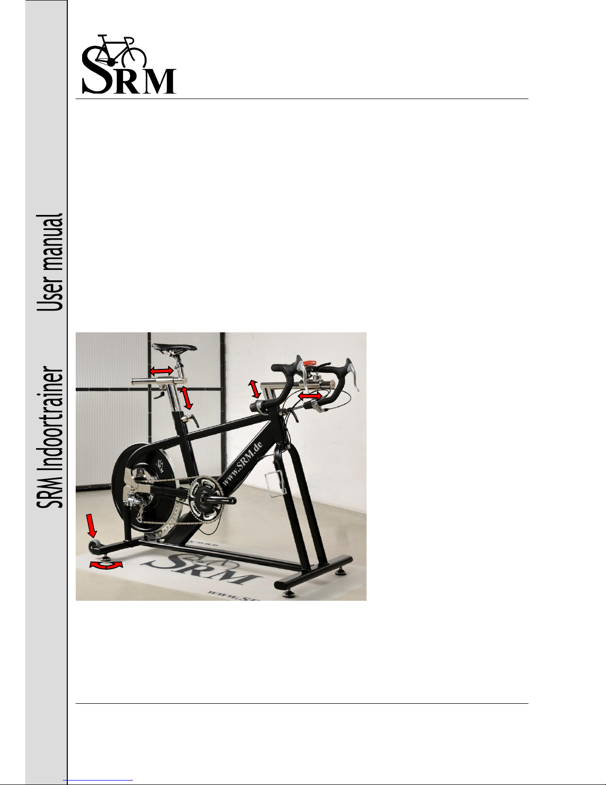
Adjusting the seat position
The SRM Indoortrainer is construct-
ed for all riders between 165 cm and
200 cm height.
You can adjust your seat position
until you find your optimum position.
The position of the saddle as well as
the handlebar are adjustable in
height and setback/ reach, as shown
by the red arrows.
The four feet are height adjustable to
compensate for uneven floor levels.
The Indoortrainer has two wheels for
easy movement without lifting.

Schoberer Rad Messtechnik GmbH
Rudolf Schulten Str. 6
D-52428 Jülich
Tel.: +49-2461-69123-0
Fax:+49-2461-69123-17
www.SRM.de
Page 4 of 10
Indoortrainer User Manual
Clamping the sliding sections
By opening the quick-release levers,
you can quickly adjust all of the di-
mensions to meet your needs.
Open the lever, adjust the height or
distance as needed, and then close
the lever again. The lever should be
tight when closed, but don’t over
tighten them or they will stretch and
will eventually snap.
After closing the lever you can adjust
by pulling out and turning so that it
will not interfere during use.
Adjusting the handlebar
To significantly reduce the distance
to the handlebar, you can remove
the adjustment piece of the handle-
bar and turn it around completely. In
order to do this you need to take off
the front cap and the handlebar.
Then turn the adjustment piece of
the handlebar 180° and remount the
handlebar and the lid.

Schoberer Rad Messtechnik GmbH
Rudolf Schulten Str. 6
D-52428 Jülich
Tel.: +49-2461-69123-0
Fax:+49-2461-69123-17
www.SRM.de
Page 5 of 10
Indoortrainer User Manual
Rear Hub
The Indoortrainer is equipped with a continuously variable NuVinci hub N360. The hub has a gear ratio of
360 %.
Adjustment of the hub is not necessary; however, the two cables lengths may initially stretch, creating play in
the shifter and causing poor shifting performance. If this happens, tighten both cable adjusters on the shifter
equally until the play is removed. Since it is the NuVinci hub to a continuous circuit, there are no transitions.
The ratio is indicated by the line in the twist shifter.
When the line is straight, the NuVinci hub is in a large gear ratio and the
flywheel is rotating rapidly.
When the line is curved, the NuVinci hub is in a smaller gear ratio and the
flywheel is rotating slowly.
For further information about the hub please contact www.nuvinci.com

Schoberer Rad Messtechnik GmbH
Rudolf Schulten Str. 6
D-52428 Jülich
Tel.: +49-2461-69123-0
Fax:+49-2461-69123-17
www.SRM.de
Page 6 of 10
Indoortrainer User Manual
Magnetic brake
The resistance of the flywheel is
regulated via a wearless magnetic
brake, which is operated via a modi-
fied SRM SRAM twist shifter. With
this shifter, the distance between
the magnet-arm and the flywheel
can be adjusted in 40 steps.
To reduce the effort needed to
operate the magnetic brake, a system of four pulleys is used on the magnet arm.
To maintain even tension on these pulleys, a spring is fixed on a rubber cap be-
tween the magnet arm and the Indoortrainer frame.
When the shifter is in position 1, the distance from the magnet-arm and flywheel is at the maximum distance
and braking power is minimal.
When the shifter is in position 20, the distance from the magnet-arm and flywheel is at the minimum distance
and the braking power is maximal.
The cable length of the brake may initially stretch. If this happens, you can tighten both cable adjusters on the
shifter and at the frame.
The magnetic brake itself does not need maintenance.
Schoberer Rad Messtechnik GmbH
Rudolf Schulten Str. 6
D-52428 Jülich
Tel.: +49-2461-69123-0
Fax:+49-2461-69123-17
www.SRM.de
Page 7 of 10
Indoortrainer User Manual
Braking Performance
The data below is for the magnetic brake set at the factory setting with a 53 tooth chainring. As the linkage of
the magnetic brake elongates slightly from use, the actual values may differ from the data in this table.
Cadence
Brake full off/
Lowest gear
Brake full off/
highest gear
Brake full off/
lowest gear
Brake full on/
highest gear
40 rpm
5 –10 Watt
90 –100 Watt
30 –40 Watt
240 –250 Watt
50 rpm
10 –20 Watt
140 –150 Watt
50 –60 Watt
340 –350 Watt
60 rpm
20 –30 Watt
190 –200 Watt
70 –80 Watt
450 –460 Watt
70 rpm
30 –40 Watt
240 –250 Watt
90 –100 Watt
560 –570 Watt
80 rpm
40 –50 Watt
290 –300 Watt
110 –120 Watt
670 –680 Watt
90 rpm
50 –60 Watt
340 –350 Watt
140 –150 Watt
780 –790 Watt
100 rpm
60 –70 Watt
390 –400 Watt
170 –180 Watt
890 –900 Watt
110 rpm
70 –80 Watt
440 –450 Watt
200 –210 Watt
1.000 –1.010 Watt
120 rpm
80 –90 Watt
490 –500 Watt
230 –240 Watt
1.110 –1.120 Watt
130 rpm
90 –100 Watt
540 –590 Watt
260 –270 Watt
1.220 –1.230 Watt
140 rpm
100 –110 Watt
590 –600Watt
290 –300 Watt
1.330 –1.340 Watt
Adjusting the braking power
If the factory setting of the braking power is too strong or too weak, try the following:
1. Increase braking power by installing a larger outer chainring
2. Decrease braking power by moving the chain to the smaller inner chainring
3. Increase braking power by moving the magnetic brake closer to the flywheel
4. Reduce braking power by moving the magnetic brake further from the flywheel

Schoberer Rad Messtechnik GmbH
Rudolf Schulten Str. 6
D-52428 Jülich
Tel.: +49-2461-69123-0
Fax:+49-2461-69123-17
www.SRM.de
Page 8 of 10
Indoortrainer User Manual
Adjusting the magnetic brake
Eventually the cable winch to adjust the distance between the magnets and the wheel can lengthen because
of heavy use, so the magnet rocker has to be readjusted from time to time. Please adjust the rocker so that
the distance of the magnets to the aluminium ring is 3-5 mm for the first and last magnet. To clamp the cable,
turn the adjusting screw outwards first.
Before you align the magnet rocker, put a piece of cardboard between the magnet rocker and the fly-
wheel. This is to make sure that the magnets don’t touch the flywheel, because it would be very diffi-
cult to detach them again.
To adjust the upper catch you need to loosen the cable with a 10 mm ring wrench and the attachment of the
magnet rocker with an 8mm hexagon wrench (don’t unscrew completely), and then move the magnet rocker
as far as needed. Then retighten the screws. The lower catch can be adjusted by turning the allen screw.
Special Features
The magnet for switching on the PowerMeter is attached by a cable-tie and heat shrink tubing under the bot-
tom bracket. If you do not see power or cadence displayed, first check if the magnet is present and positioned
properly.
Speed is sent from a speed sensor on the rear frame of the Indoortrainer and a magnet on the flywheel. If you
do not see speed displayed, first check if the magnet is present and positioned properly.
Since the NuVinci N360 sprocket wider than normal, the use of a KMC X-8-99 chain or equivalent is recom-
mended.

Schoberer Rad Messtechnik GmbH
Rudolf Schulten Str. 6
D-52428 Jülich
Tel.: +49-2461-69123-0
Fax:+49-2461-69123-17
www.SRM.de
Page 9 of 10
Indoortrainer User Manual
Caring for your Indoortrainer
To get the most life from your Indoortrainer, we recommend that you wipe off the sweat after every workout.
Wipe the entire frame, handlebar, seat, and seat-tube with a clean soft cloth. We also recommend that the
surfaces of the Indoortrainer be treated with a silicone polish to further protect the surfaces.
Avoid touching the aluminum flywheel-ring with sweaty or dirty hands. Sweat is a very aggessive fluid which
leads to the oxidation of aluminum. To maintain the aluminum flywheel-ring, we recommend that you clean it
regularly and use a stainless-steel or chrome polish. Lubricate the chain as needed with a „dry“ bicycle chain
lubricant
Resetting the magnetic brake cable
If the magnetic brake cable comes out of the pulley system, it is not necessary to loosen the cable-anchor
bolt. Wrap the cable around the pulleys by starting with the cable end that is attached to the magnet-arm.
Wrap the cable under the inner pulley attached to the frame.
Next, wrap the cable under the inner pulley attached to the
magnet-arm. Third, wrap the cable under the outer pulley at-
tached to the frame. Lastly, wrap the cable under the outer pul-
ley attached to the magnet-arm.

Schoberer Rad Messtechnik GmbH
Rudolf Schulten Str. 6
D-52428 Jülich
Tel.: +49-2461-69123-0
Fax:+49-2461-69123-17
www.SRM.de
Page 10 of 10
Indoortrainer User Manual
Adjustment range of Indoortrainer
Measurement
Distance
Saddle height, maximum from BB
90 cm
Saddle height, minimum from BB
65 cm
Saddle setback, maximum behind BB
6 –14 cm
Saddle setback, maximum in front of BB
7 –15 cm
Handlebar height, minimum horizontal from BB
52 cm
Handlebar reach, minimum from BB
33 cm
Handlebar height, minimum horizontal from BB
73 cm
Handlebar reach, minimum from BB
55 cm
Saddle tip to handlebar, maximum
65 cm
Saddle tip to handlebar, minimum
22 cm
Technical Data and Specifications
Materials used
Stainless steel, powder-coated steel, chrome steel, alumi-
num
Weight
62,5 kg
Flywheel weight
29, 5 kg
Circumferrence of the
flywheel
1.430 mm
Dimensions (L x W)
1330 cm x 550 mm
Bottom Bracket
BSA 68 mm
Seatpost diameter
27,2 mm
Rear Hub
NuVinci®N360™, continuously variable gear hub
Chain tensioner
Shimano
Brake
Magnetic-brake
Saddle
Prologo
Handlebar
31,8 mm
Chain
KMC X-8-99
Other manuals for Indoortrainer
1
Table of contents
Other SRM Exercise Bike manuals

Popular Exercise Bike manuals by other brands

Life Fitness
Life Fitness Arctic Silver 95CEZ parts manual

Sunny Health & Fitness
Sunny Health & Fitness PERFORMANCE INTERACTIVE SF-B220030 user manual

Cascade
Cascade CMX Pro owner's manual

NordicTrack
NordicTrack Commercial S22i Studio Cycle user manual
ICON
ICON NTEX12921.4 user manual

Star Trac
Star Trac 4-RB Assembly manual


